

Page 1
Modular I/O System
DeviceNet
750-346
Manual
Technical Description,
Installation and
Configuration
Page 2

ii • General
Copyright © 2007 by WAGO Kontakttechnik GmbH & Co. KG
All rights reserved.
WAGO Kontakttechnik GmbH & Co. KG
Hansastraße 27
D-32423 Minden
Phone: +49 (0) 571/8 87 – 0
Fax: +49 (0) 571/8 87 – 1 69
E-Mail: info@wago.com
Web: http://www.wago.com
Technical Support
Phone: +49 (0) 571/8 87 – 5 55
Fax: +49 (0) 571/8 87 – 85 55
E-Mail: support@wago.com
Every conceivable measure has been taken to ensure the correctness and completeness of this documentation. However, as errors can never be fully excluded we would appreciate any information or ideas at any time.
E-Mail: documentation@wago.com
We wish to point out that the software and hardware terms as well as the
trademarks of companies used and/or mentioned in the present manual are
generally trademark or patent protected.
WAGO-I/O-SYSTEM 750
DeviceNet
Page 3

Table of Contents • iii
TABLE OF CONTENTS
1 Important Notes ..........................................................................................6
1.1 Legal Principles........................................................................................6
1.1.1 Copyright.............................................................................................6
1.1.2 Personnel Qualification .......................................................................6
1.1.3 Conforming Use of Series 750............................................................7
1.1.4 Technical Condition of the Devices....................................................7
1.2 Standards and Regulations for Operating the 750 Series.........................7
1.3 Symbols....................................................................................................8
1.4 Safety Information....................................................................................9
1.5 Font Conventions ...................................................................................10
1.6 Number Notation....................................................................................10
1.7 Scope......................................................................................................10
1.8 Abbreviation...........................................................................................11
2 The WAGO-I/O-SYSTEM 750................................................................12
2.1 System Description.................................................................................12
2.2 Technical Data........................................................................................13
2.3 Manufacturing Number..........................................................................16
2.4 Component Update.................................................................................17
2.5 Storage, Assembly and Transport ..........................................................18
2.6 Mechanical Setup...................................................................................18
2.6.1 Installation Position...........................................................................18
2.6.2 Total Expansion.................................................................................18
2.6.3 Assembly onto Carrier Rail...............................................................19
2.6.3.1 Carrier rail properties....................................................................19
2.6.3.2 WAGO DIN Rail ..........................................................................20
2.6.4 Spacing ..............................................................................................20
2.6.5 Plugging and Removal of the Components.......................................21
2.6.6 Assembly Sequence...........................................................................22
2.6.7 Internal Bus / Data Contacts..............................................................23
2.6.8 Power Contacts..................................................................................24
2.6.9 Wire connection.................................................................................25
2.7 Power Supply .........................................................................................26
2.7.1 Isolation .............................................................................................26
2.7.2 System Supply...................................................................................27
2.7.2.1 Connection....................................................................................27
2.7.2.2 Alignment .....................................................................................28
2.7.3 Field Supply.......................................................................................30
2.7.3.1 Connection....................................................................................30
2.7.3.2 Fusing............................................................................................31
2.7.4 Supply example .................................................................................34
2.7.5 Power Supply Unit.............................................................................35
2.8 Grounding...............................................................................................36
2.8.1 Grounding the DIN Rail....................................................................36
2.8.1.1 Framework Assembly...................................................................36
2.8.1.2 Insulated Assembly.......................................................................36
WAGO-I/O-SYSTEM 750
DeviceNet
Page 4

iv • Table of Contents
2.8.2 Grounding Function...........................................................................37
2.8.3 Grounding Protection.........................................................................38
2.9 Shielding (Screening).............................................................................39
2.9.1 General...............................................................................................39
2.9.2 Bus Conductors..................................................................................39
2.9.3 Signal Conductors..............................................................................39
2.9.4 WAGO Shield (Screen) Connecting System.....................................40
2.10 Assembly Guidelines / Standards...........................................................40
3 Fieldbus Coupler.......................................................................................42
3.1 Fieldbus Coupler 750-346......................................................................42
3.1.1 Description.........................................................................................43
3.1.2 Hardware............................................................................................44
3.1.2.1 View..............................................................................................44
3.1.2.2 Device Supply...............................................................................45
3.1.2.3 Fieldbus Connection .....................................................................45
3.1.2.4 Display Elements ..........................................................................46
3.1.2.5 Configuration Interface.................................................................47
3.1.2.6 Hardware Address (MAC ID).......................................................47
3.1.2.7 Setting the Baud Rate....................................................................48
3.1.3 Operating System...............................................................................48
3.1.4 Process Image....................................................................................49
3.1.5 Data Exchange...................................................................................50
3.1.5.1 Communication Interfaces............................................................51
3.1.5.2 Memory Areas ..............................................................................51
3.1.5.3 Addressing ....................................................................................52
3.1.6 Configuration Software .....................................................................54
3.1.7 Starting up DeviceNet Fieldbus Nodes..............................................54
3.1.7.1 Connecting the PC and Fieldbus Node .........................................54
3.1.7.2 Setting the MAC ID and Baud Rate .............................................54
3.1.7.3 Configuration with Static Assembly.............................................55
3.1.8 LED Display......................................................................................59
3.1.8.1 Node status – Blink code from the 'I/O' LED ...............................60
3.1.9 Technical Data...................................................................................67
4 DeviceNet ...................................................................................................68
4.1 Description .............................................................................................68
4.2 Network Architecture.............................................................................69
4.2.1 Transmission Media...........................................................................69
4.2.1.1 Type of Cable................................................................................69
4.2.1.2 Cable Types ..................................................................................69
4.2.1.3 Maximum Bus Length ..................................................................70
4.2.2 Cabling...............................................................................................70
4.2.3 Network Topology.............................................................................72
4.2.4 Network Grounding...........................................................................73
4.2.5 Interface Modules..............................................................................73
4.3 Network Communication .......................................................................74
4.3.1 Objects, Classes, Instances and Attributes ........................................74
4.4 Module Characteristics...........................................................................75
4.4.1 Communication Model......................................................................75
WAGO-I/O-SYSTEM 750
DeviceNet
Page 5

Table of Contents • v
4.4.1.1 Message Groups............................................................................75
4.4.1.2 Message Types..............................................................................75
4.4.2 I/O Messaging Connections...............................................................76
4.5 Process data and Diagnostic Status........................................................76
4.5.1 Process Image....................................................................................76
4.5.1.1 Assembly Instances.......................................................................77
4.6 Configuration / Parametering with the Object Model............................79
4.6.1 EDS Files...........................................................................................79
4.6.2 Object Model.....................................................................................80
4.6.2.1 Object Model for Coupler 750-346...............................................81
5 I/O Modules ...............................................................................................98
5.1 Overview................................................................................................98
5.1.1 Digital Input Modules........................................................................98
5.1.2 Digital Output Modules...................................................................100
5.1.3 Analog Intput Modules....................................................................101
5.1.4 Analog Output Modules..................................................................102
5.1.5 Special Modules...............................................................................103
5.1.6 System Modules ..............................................................................104
5.2 Process Data Architecture for DeviceNet ............................................105
5.2.1 Digital Input Modules......................................................................105
5.2.2 Digital Output Modules...................................................................107
5.2.3 Analog Input Modules.....................................................................111
5.2.4 Analog Output Modules..................................................................113
5.2.5 Specialty Modules ...........................................................................114
5.2.6 System Modules ..............................................................................126
6 Glossary....................................................................................................127
7 Literature List .........................................................................................128
8 Index.........................................................................................................129
WAGO-I/O-SYSTEM 750
DeviceNet
Page 6
6 • Important Notes
Legal Principles
1 Important Notes
This section provides only a summary of the most important safety requirements and notes which will be mentioned in the individual sections. To protect
your health and prevent damage to the devices, it is essential to read and carefully follow the safety guidelines.
1.1 Legal Principles
1.1.1 Copyright
This manual including all figures and illustrations contained therein is subject
to copyright. Any use of this manual which infringes the copyright provisions
stipulated herein, is not permitted. Reproduction, translation and electronic
and phototechnical archiving and amendments require the written consent of
WAGO Kontakttechnik GmbH & Co. KG, Minden. Non-observance will entail the right of claims for damages.
WAGO Kontakttechnik GmbH & Co. KG reserves the right of changes serving technical progress.
All rights developing from the issue of a patent or the legal protection of utility patents are reserved to WAGO Kontakttechnik GmbH & Co. KG. Thirdparty products are always indicated without any notes concerning patent
rights. Thus, the existence of such rights must not be excluded.
1.1.2 Personnel Qualification
The use of the product described in this manual requires special qualifications,
as shown in the following table:
Activity Electrical specialist
Assembly
Commissioning
Programming
Maintenance
Troubleshooting
Instructed personnel*)
X X
X X
X
X X
X
Specialists**) having
qualifications in PLC
programming
Disassembly
*) Instructed persons have been tr ained by qualified personnel or electrical specialists.
**) A specialist is someone who, through technical training, knowledge and experience,
demonstrates the ability to meet the relevant specifications and identify potential dangers in
the mentioned field of activity.
X X
All personnel must be familiar with the applicable standards.
WAGO Kontakttechnik GmbH & Co. KG declines any liability resulting from
WAGO-I/O-SYSTEM 750
DeviceNet
Page 7

Important Notes • 7 Standards and Regulations for Operating the 750 Series
improper action and damage to WAGO products and third party products due to
non-observance of the information contained in this manual.
1.1.3 Conforming Use of Series 750
The couplers and controllers of the modular I/O System 750 receive digital
and analog signals from the I/O modules and sensors and transmit them to the
actuators or higher level control systems. Using the WAGO controllers, the
signals can also be (pre-)processed.
The device is designed for IP20 protection class. It is protected against finger
touch and solid impurities up to 12.5mm diameter, but not against water penetration. Unless otherwise specified, the device must not be operated in wet and
dusty environments.
1.1.4 Technical Condition of the Devices
For each individual application, the components are supplied from the factory
with a dedicated hardware and software configuration. Changes in hardware,
software and firmware are only admitted within the framework of the possibilities documented in the manuals. All changes to the hardware or software
and the non-conforming use of the components entail the exclusion of liability
on the part of WAGO Kontakttechnik GmbH & Co. KG.
Please direct any requirements pertaining to a modified and/or new hardware
or software configuration directly to WAGO Kontakttechnik GmbH & Co.
KG.
1.2 Standards and Regulations for Operating the 750 Series
Please observe the standards and regulations that are relevant to your installation:
• The data and power lines must be connected and installed in compliance
with the standards to avoid failures on your installation and eliminate any
danger to personnel.
• For installation, startup, maintenance and repair, please observe the accident prevention regulations of your machine (e.g. BGV A 3, "Electrical Installations and Equipment").
• Emergency stop functions and equipment must not be made ineffective.
See relevant standards (e.g. DIN EN 418).
• Your installation must be equipped in accordance to the EMC guidelines so
that electromagnetic interferences can be eliminated.
• Operating 750 Series components in home applications without further
measures is only permitted if they meet the emission limits (emissions of
interference) according to EN 61000-6-3. You will find the relevant information in the section on "WAGO-I/O-SYSTEM 750" Æ "System Description" Æ "Technical Data".
WAGO-I/O-SYSTEM 750
DeviceNet
Page 8

8 • Important Notes
Symbols
• Please observe the safety measures against electrostatic discharge accord-
• The relevant valid and applicable standards and guidelines concerning the
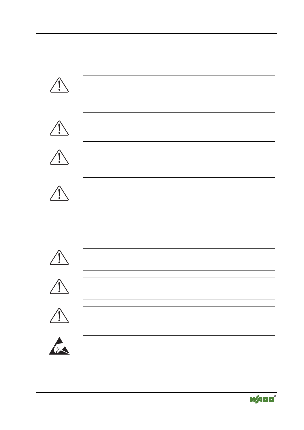
1.3 Symbols
Danger
Always observe this information to protect persons from injury.
Warning
Always observe this information to prevent damage to the device.
Attention
Marginal conditions that must always be observed to ensure smooth and efficient operation.
ing to DIN EN 61340-5-1/-3. When handling the modules, ensure that the
environment (persons, workplace and packing) is well grounded.
installation of switch cabinets are to be observed.
ESD (Electrostatic Discharge)
Warning of damage to the components through electrostatic discharge. Observe the precautionary measure for handling components at risk of electrostatic discharge.
Note
Make important notes that are to be complied with so that a trouble-free and
efficient device operation can be guaranteed.
Additional Information
References to additional literature, manuals, data sheets and INTERNET
pages.
WAGO-I/O-SYSTEM 750
DeviceNet
Page 9
Important Notes • 9
Safety Information
1.4 Safety Information
When connecting the device to your installation and during operation, the following safety notes must be observed:
Danger
The WAGO-I/O-SYSTEM 750 and its components are an open system. It
must only be assembled in housings, cabinets or in electrical operation
rooms. Access is only permitted via a key or tool to authorized qualified personnel.
Danger
All power sources to the device must always be switched off before carrying
out any installation, repair or maintenance work.
Warning
Replace defective or damaged device/module (e.g. in the event of deformed
contacts), as the functionality of fieldbus station in question can no longer be
ensured on a long-term basis.
Warning
The components are not resistant against materials having seeping and insulating properties. Belonging to this group of materials is: e.g. aerosols, silicones, triglycerides (found in some hand creams). If it cannot be ruled out
that these materials appear in the component environment, then the components must be installed in an enclosure that is resistant against the above mentioned materials. Clean tools and materials are generally required to operate
the device/module.
Warning
Soiled contacts must be cleaned using oil-free compressed air or with ethyl
alcohol and leather cloths.
Warning
Do not use contact sprays, which could possibly impair the functioning of the
contact area.
Warning
Avoid reverse polarity of data and power lines, as this may damage the devices.
ESD (Electrostatic Discharge)
The devices are equipped with electronic components that may be destroyed
by electrostatic discharge when touched.
WAGO-I/O-SYSTEM 750
DeviceNet
Page 10
10 • Important Notes
Font Conventions
1.5 Font Conventions
italic
italic
\
END
< >
Courier
1.6 Number Notation
Names of paths and files are marked in italic.
e.g.: C:\Programs\WAGO-IO-CHECK
Menu items are marked in bold italic.
e.g.: Save
A backslash between two names characterizes the selection of a menu point from a menu.
e.g.: File \ New
Press buttons are marked as bold with small capitals
e.g.:
ENTER
Keys are marked bold within angle brackets
e.g.: <F5>
The print font for program codes is Courier.
e.g.: END_VAR
1.7 Scope
Number code Example Note
Decimal 100 Normal notation
Hexadecimal 0x64 C notation
Binary '100'
'0110.0100'
Within ',
Nibble separated with dots
This manual describes the modular WAGO-I/O-SYSTEM 750 with the
DeviceNet ECO fieldbus coupler.
Item-No. Description
750-346 DeviceNet ECO fieldbus coupler, 125 kBaud ... 500 kBaud;
digital and analog signals
WAGO-I/O-SYSTEM 750
DeviceNet
Page 11

Important Notes • 11 Abbreviation
1.8 Abbreviation
AI
AO
CAL
CAN
DI
DIP
DO
EDS
I/O
ID
Idx
ISO/ OSI
HB
HW
LB
MAC ID
Analog Input
Analog Output
CAN Application Layer
Controller Area Network
Digital Input
Dual In-line Package
Digital Output
Electronic Data Sheets
Input/Output
Identifier, Identification
Index
International Organization for Standardization /
Open Systems Interconnection (model )
High Byte
Hardware
Low Byte
Media Access Control Identifier (nodeaddress)
MS
NMT
NS
RO
RW
SW
Module Status
Network Management
Network Status
Read Only
Read/Write
Software
WAGO-I/O-SYSTEM 750
DeviceNet
Page 12
12 • The WAGO-I/O-SYSTEM 750 System Description
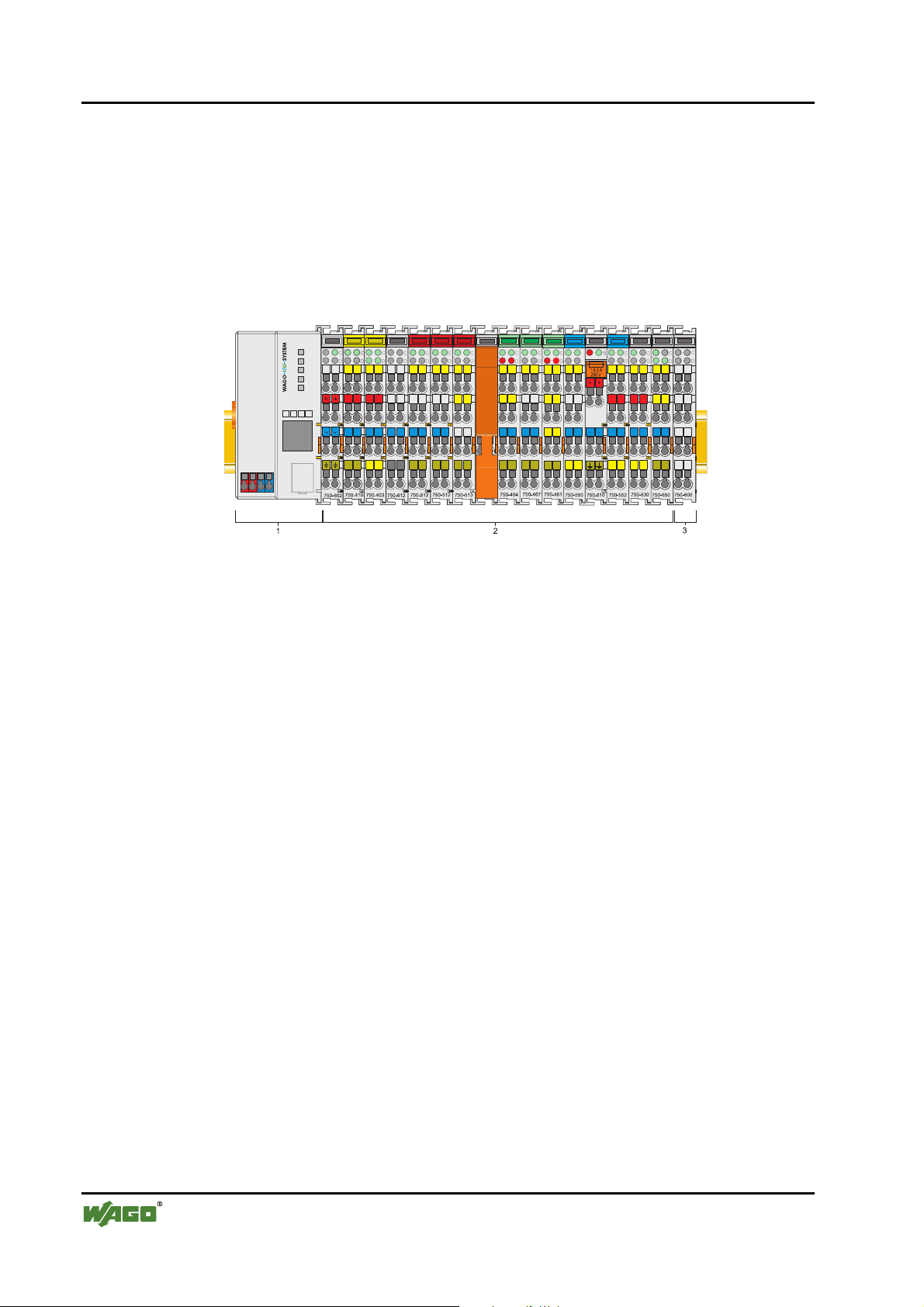
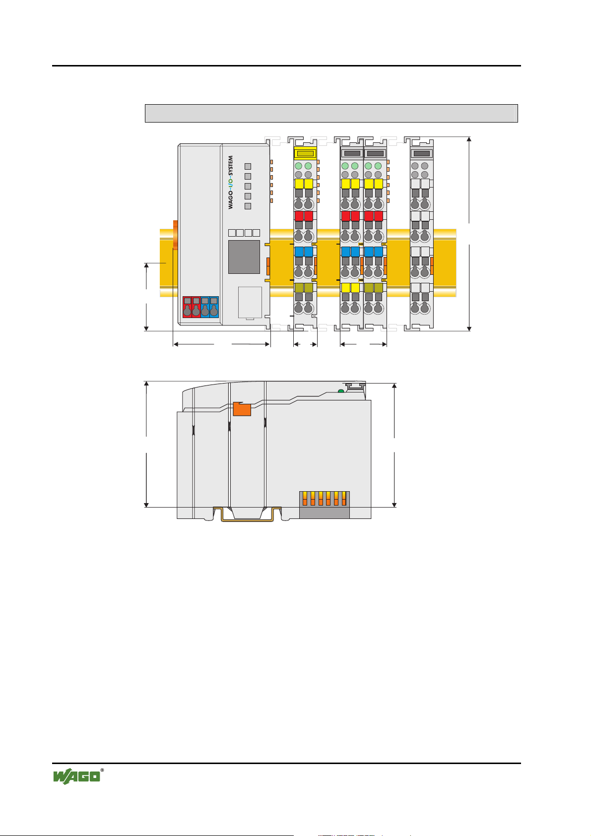
2 The WAGO-I/O-SYSTEM 750
2.1 System Description
The WAGO-I/O-SYSTEM 750 is a modular, fieldbus independent I/O system.
In this description, it is comprised of an ECO fieldbus coupler (1) and up to
64 connected fieldbus modules (2) for any type of signal. Together, these
make up the fieldbus node. The end module (3) completes the node.
Fig. 2-1: Fieldbus node g0xxx14x
ECO Couplers for fieldbus systems such as PROFIBUS, INTERBUS,
CANopen and DeviceNet are available.
The ECO coupler contains the fieldbus interface, electronics and a power supply for the system. The fieldbus interface forms the physical interface to the
relevant fieldbus. The electronics process the data of the bus modules and
make it available for the fieldbus communication. The 24 V system supply is
fed in via the voltage supply.
The ECO coupler is primarily conceived for applications with digital I/O functions. In addition, modules for most different digital and analog I/O functions
as well as special functions can be connected to the ECO coupler. The communication between the ECO coupler and the bus modules is carried out via
an internal bus.
The WAGO-I/O-SYSTEM 750 has a clear port level with LEDs for status indication, insertable mini WSB markers and pullout group marker carriers. The
3-wire technology supplemented by a ground wire connection allows for direct
sensor/actuator wiring.
WAGO-I/O-SYSTEM 750
DeviceNet
Page 13
The WAGO-I/O-SYSTEM 750 • 13 Technical Data
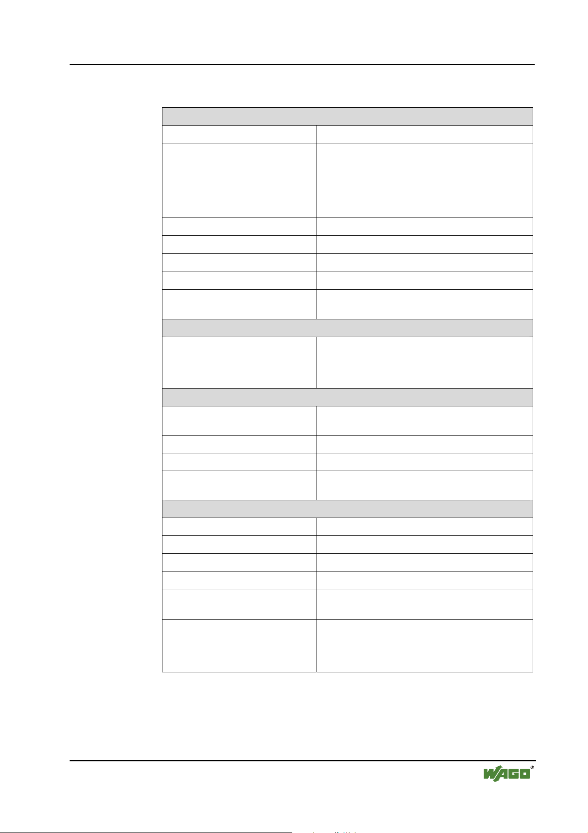
2.2 Technical Data
Mechanic
Material Polycarbona te, Polyamide 6.6
Dimensions
- ECO coupler
- I/O module, single
- I/O module, double
- 50 mm x 65* mm x 100 mm
- 12 mm x 64* mm x 100 mm
- 24 mm x 64* mm x 100 mm
* from upper edge of DIN 35 rail
Installation on DIN 35 with interlock
modular by double featherkey-dovetail
Mounting position any position
Length of entire node
≤ 830 mm
Marking marking label type 247 and 248
paper marking label 8 x 47 mm
Wire range
Wire range CAGE CLAMP® Connection
0,08 mm² ... 2.5 mm²
AWG 28-14
8 – 9 mm Stripped length
Contacts
Power jumpers contacts blade/spring contact
self-cleaning
Current via power contacts
Voltage drop at I
< 1 V/64 modules
max
10 A
max
Data contacts slide contact, hard gold plated
1,5µm, self-cleaning
Climatic environmental conditions
Operating temperature 0 °C ... 55 °C
Storage temperature -20 °C ... +85 °C
Relative humidity 5% to 95 % without condensation
Resistance to harmful substances acc. To IEC 60068-2-42 and IEC 60068-2-43
Maximum pollutant concentration at
relative humidity < 75%
SO
≤ 25 ppm
2
S ≤ 10 ppm
H
2
Special conditions Ensure that additional measures for components are
taken, which are used in an environment involving:
– dust, caustic vapors or gasses
– ionization radiation.
WAGO-I/O-SYSTEM 750
DeviceNet
Page 14
14 • The WAGO-I/O-SYSTEM 750
Technical Data
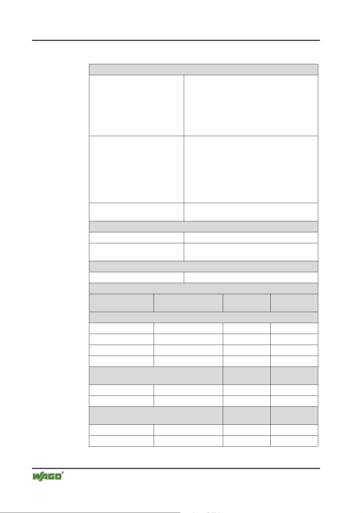
Mechanical strength
Vibration resistance acc. to IEC 60068-2-6
Comment to the vibration restistance:
a) Type of oscillation:
sweep with a rate of change of 1 octave per minute
10 Hz ≤ f < 57 Hz, const. Amplitude 0,075 mm
57 Hz ≤ f < 150 Hz, const. Acceleration 1 g
b) Period of oscillation:
10 sweep per axis in each of the 3 vertical axes
Shock resistance acc. to IEC 60068-2-27
Comment to the shock restistance:
a) Type of impulse: half sinusoidal
b) Intensity of impulse:
15 g peak value, 11 ms maintenance time
c) Route of impulse:
3 impulses in each pos. And neg. direction of the
3 vertical axes of the test object, this means
18 impulses in all
Free fall acc. to IEC 60068-2-32
≤ 1m (module in original packing)
Safe electrical isolation
Air and creepage distance acc. to IEC 60664-1
Degree of pollution
acc. to IEC 61131-2
Degree of protection
Degree of protection IP 20
Electromagnetic compatibility*
Directive Test values Strength
Immunity to interference acc. to EN 50082-2 (96)
EN 61000-4-2 4kV/8kV (2/4) B
EN 61000-4-3 10V/m 80% AM (3) A
EN 61000-4-4 2kV (3/4) B
EN 61000-4-6 10V/m 80% AM (3) A
Emission of interference acc. to
EN 50081-2 (94)
2
Evaluation
class
Measuring
distance
criteria
Class
EN 55011 30 dBµV/m (30m) A
37 dBµV/m
Emission of interference acc. to
EN 50081-1 (93)
EN 55022 30 dBµV/m (10m) B
37 dBµV/m
* Exception: 750-630, 750-631
WAGO-I/O-SYSTEM 750
DeviceNet
Measuring
distance
Class
Page 15
The WAGO-I/O-SYSTEM 750 • 15
Technical Data
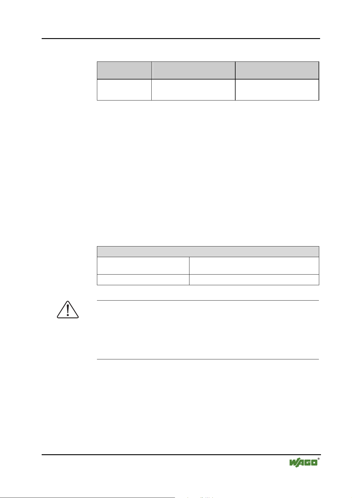
Range of application
Industrial areas EN 50081-2 : 1993 EN 50082-2 : 1996
Residential areas EN 50081-1 : 1993*) EN 50082-1 : 1992
*)
The system meets the requirements on emission of interference in residential areas with
the fieldbus coupler/controller for:
ETHERNET
LonWorks
CANopen
DeviceNet
MODBUS
With a special permit, the system can also be implemented with other fieldbus couplers/controllers in residential areas (housing, commercial and business areas, small-scale
enterprises). The special permit can be obtained from an authority or inspection office. In
Germany, the Federal Office for Post and Telecommunications and its branch offices
issues the permit.
It is possible to use other field bus couplers / controllers under certain boundary conditions. Please contact WAGO Kontakttechnik GmbH.
Required specification
emission of interference
750-342/-842
750-319/-819
750-337/-837
750-306/-806
750-312/-314/ -315/ -316
750-812/-814/ -815/ -816
Required specification
immunity to interference
Maximum power dissipation of the components
Bus modules 0.8 W / bus terminal (total power dissipation, sys-
tem/field)
ECO fieldbus coupler 2.0 W / coupler
Warning
The power dissipation of all installed components must not exceed the maximum conductible power of the housing (cabinet).
When dimensioning the housing, care is to be taken that even under high external temperatures, the temperature inside the housing does not exceed the
permissible ambient temperature of 55 °C.
WAGO-I/O-SYSTEM 750
DeviceNet
Page 16
16 • The WAGO-I/O-SYSTEM 750
Manufacturing Number
Dimensions
35
65
50
A
B
A
C
D
A
C
B
B
D
A
C
D
C
B
D
100
12
24
64
Side view
Dimensions in mm
Fig. 2-2: Dimensions g0xxx15e
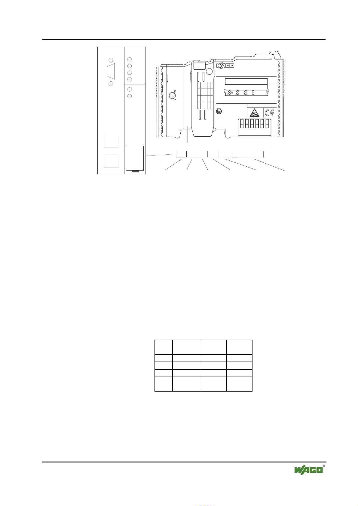
2.3 Manufacturing Number
The manufacturing number indicates the delivery status directly after production.
This number is part of the lateral marking on the component.
In addition, starting from calender week 43/2000 the manufacturing number is
also printed on the cover of the configuration interface of the fieldbus coupler.
WAGO-I/O-SYSTEM 750
DeviceNet
Page 17
The WAGO-I/O-SYSTEM 750 • 17 Component Update
PROFIBUS
ITEM-NO.:750-333
ITEM-NO.:750-333
PROFIBUS DP 12 MBd /DPV1
Hansastr. 27
Hansastr. 27
GL
D-32423 Minden
D-32423 Minden
24V DC
24V DC
AWG 28-14
AWG 28-14
55°C max ambient
55°C max ambient
72072
72072
DS
NO
SW
HW
FWL
II3GD
0
II3GD
DEMKO 02 ATEX132273 X
DEMKO 02 ATEX132273 X
EEx nA II T4
EEx nA II T4
2
0
Hardware
version
LISTED 22ZA AND 22XM
LISTED 22ZA AND 22XM
0103000203-B000000
750-333
WAGO - I/O - SYSTEM
01030002
03-B
060606
72072
Calendar
week
Fig. 2-3: Example: Manufacturing Number of a PROFIBUS fieldbus coupler 750-333
0103000203-B060606
Manufacturing Number
0
1
3
0
0
0
Year Software
version
PROFIBUS DP 12 MBd /DPV1
24 V
-
+
0V
0V
Power Supply
Power Supply
Field
3
-B060606
Power Supply
Electronic
Electronic
PATENTS PENDING
PATENTS PENDING
Firmware Loader
version
Internal
Number
G01xx15e
The manufacturing number consists of the production week and year, the
software version (if available), the hardware version of the component, the
firmware loader (if available) and further internal information for
WAGO Kontakttechnik GmbH.
2.4 Component Update
For the case of an Update of one component, the lateral marking on each component contains a prepared matrix.
This matrix makes columns available for altogether three updates to the entry
of the current update data, like production order number (NO; starting from
calendar week 13/2004), update date (DS), software version (SW), hardware
version (HW) and the firmware loader version (FWL, if available).
Update Matrix
Current Version data for: 1. Update 2. Update 3. Update
Production Order
Number
Datestamp
Software index
Hardware index
Firmware loader
index
NO
DS
SW
HW
FWL
<- Only starting from Calen-
dar week 13/2004
<- Only for coupler/controller
If the update of a component took place, the current version data are registered
into the columns of the matrix.
Additionally with the update of a ECO fieldbus coupler also the cover of the
configuration interface of the coupler is printed on with the current manufacturing and production order number.
The original manufacturing data on the housing of the component remain
thereby.
WAGO-I/O-SYSTEM 750
DeviceNet
Page 18
18 • The WAGO-I/O-SYSTEM 750 Storage, Assembly and Transport
2.5 Storage, Assembly and Transport
Wherever possible, the components are to be stored in their original packaging. Likewise, the original packaging provides optimal protection during
transport.
When assembling or repacking the components, the contacts must not be
soiled or damaged. The components must be stored and transported in appropriate containers/packaging. Thereby, the ESD information is to be regarded.
Statically shielded transport bags with metal coatings are to be used for the
transport of open components for which soiling with amine, amide and silicone has been ruled out, e.g. 3M 1900E.
2.6 Mechanical Setup
2.6.1 Installation Position
Along with horizontal and vertical installation, all other installation positions
are allowed.
Attention
In the case of vertical assembly, an end stop has to be mounted as an additional safeguard against slipping.
WAGO item 249-116 End stop for DIN 35 rail, 6 mm wide
WAGO item 249-117 End stop for DIN 35 rail, 10 mm wide
2.6.2 Total Expansion
The maximum total expansion of a node is calculated as follows:
Quantity Width Components
1 50 mm ECO coupler
64 12 mm bus modules
- inputs / outputs
- power supply modules
- etc.
1 12 mm end module
sum 830 mm
Warning
The maximal total expansion of a node must not exceed 830 mm
WAGO-I/O-SYSTEM 750
DeviceNet
Page 19

The WAGO-I/O-SYSTEM 750 • 19
Mechanical Setup
2.6.3 Assembly onto Carrier Rail
2.6.3.1 Carrier rail properties
All system components can be snapped directly onto a carrier rail in accordance with the European standard EN 50022 (DIN 35).
Warning
WAGO supplies standardized carrier rails that are optimal for use with the
I/O system. If other carrier rails are used, then a technical inspection and approval of the rail by WAGO Kontakttechnik GmbH should take place.
Carrier rails have different mechanical and electrical properties. For the optimal system setup on a carrier rail, certain guidelines must be observed:
• The material must be non-corrosive.
• Most components have a contact to the carrier rail to ground electro-
magnetic disturbances. In order to avoid corrosion, this tin-plated carrier
rail contact must not form a galvanic cell with the material of the carrier
rail which generates a differential voltage above 0.5 V (saline solution of
0.3% at 20°C) .
• The carrier rail must optimally support the EMC measures integrated into
the system and the shielding of the bus module connections.
• A sufficiently stable carrier rail should be selected and, if necessary, several mounting points (every 20 cm) should be used in order to prevent
bending and twisting (torsion).
• The geometry of the carrier rail must not be altered in order to secure the
safe hold of the components. In particular, when shortening or mounting
the carrier rail, it must not be crushed or bent.
• The base of the I/O components extends into the profile of the carrier rail.
For carrier rails with a height of 7.5 mm, mounting points are to be riveted
under the node in the carrier rail (slotted head captive screws or blind rivets).
WAGO-I/O-SYSTEM 750
DeviceNet
Page 20
20 • The WAGO-I/O-SYSTEM 750
Mechanical Setup
2.6.3.2 WAGO DIN Rail
WAGO carrier rails meet the electrical and mechanical requirements.
Item Number Description
210-113 /-112 35 x 7.5; 1 mm; steel yellow chromated; slotted/unslotted
210-114 /-197 35 x 15; 1.5 mm; steel yello w chromated; slotted/unslotted
210-118 35 x 15; 2.3 mm; steel yello w chromated; unslotted
210-198 35 x 15; 2.3 mm; copper; unslotted
210-196 35 x 7.5; 1 mm; aluminum; unslotted
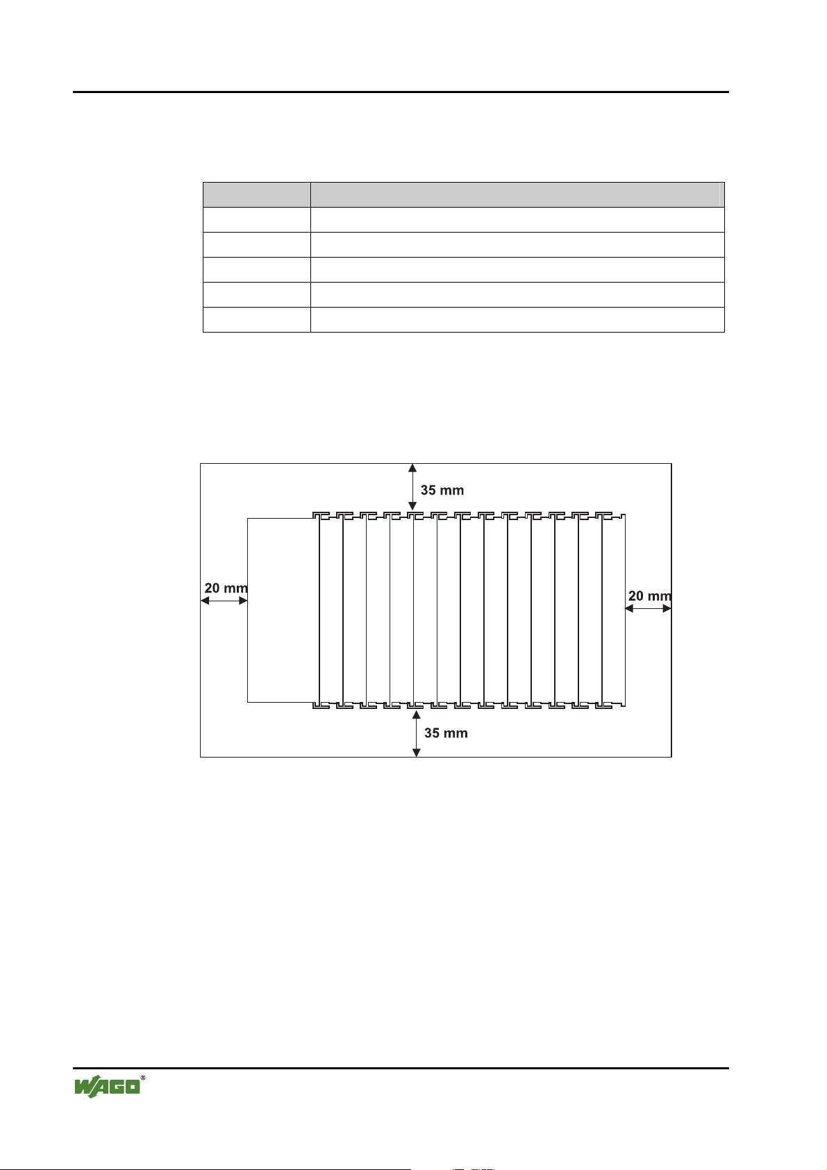
2.6.4 Spacing
The spacing between adjacent components, cable conduits, casing and frame
sides must be maintained for the complete field bus node.
Fig. 2-4: Spacing g01xx13x
The spacing creates room for heat transfer, installation or wiring. The spacing
to cable conduits also prevents conducted electromagnetic interferences from
influencing the operation.
WAGO-I/O-SYSTEM 750
DeviceNet
Page 21
The WAGO-I/O-SYSTEM 750 • 21
Mechanical Setup
2.6.5 Plugging and Removal of the Components
Warning
Before work is done on the components, the voltage supply must be turned
off.
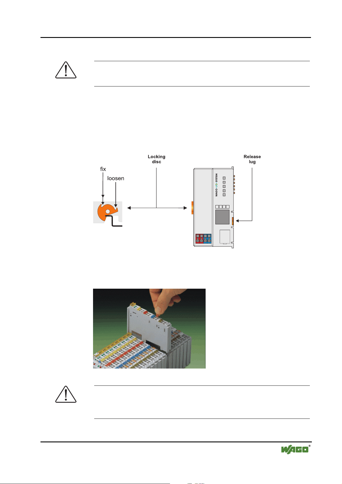
In order to safeguard the ECO coupler from jamming, it should be fixed onto
the carrier rail with the locking disc. To do so, push on the upper groove of the
locking disc using a screwdriver.
To pull out the ECO fieldbus coupler, release the locking disc by pressing on
the bottom groove with a screwdriver and then pulling the orange colored
unlocking lug.
Fig. 2-5: Coupler and unlocking lug g0xxx18e
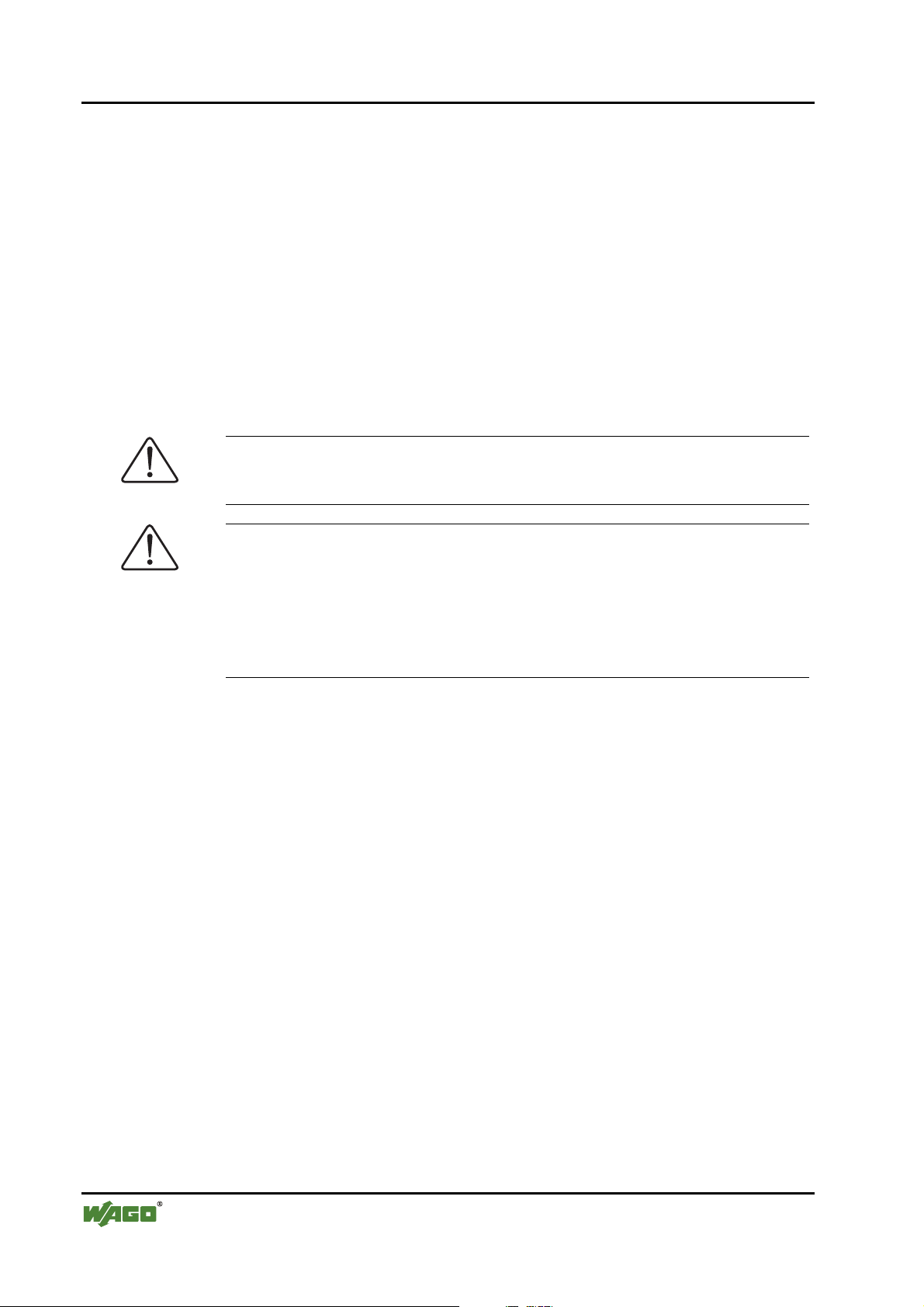
It is also possible to release an individual I/O module from the unit by pulling
an unlocking lug.
Fig. 2-6: removing bus terminal p0xxx01x
Danger
Ensure that an interruption of the PE will not result in a condition which
could endanger a person or equipment!
For planning the ring feeding of the ground wire, please see chapter 2.6.3.
WAGO-I/O-SYSTEM 750
DeviceNet
Page 22
22 • The WAGO-I/O-SYSTEM 750
Mechanical Setup
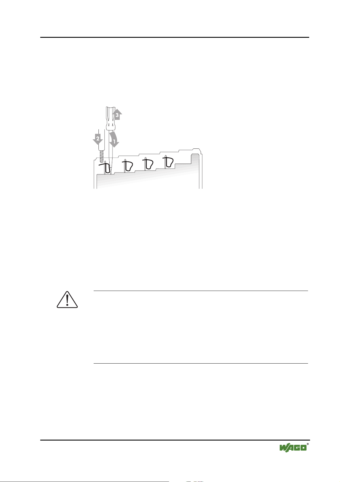
2.6.6 Assembly Sequence
All system components can be snapped directly on a carrier rail in accordance
with the European standard EN 50022 (DIN 35).
The reliable positioning and connection is made using a tongue and groove
system. Due to the automatic locking, the individual components are securely
seated on the rail after installing.
Starting with the ECO coupler, the bus modules are assembled adjacent to
each other according to the project planning. Errors in the planning of the node
in terms of the potential groups (connection via the power contacts) are recognized, as the bus modules with power contacts (male contacts) cannot be
linked to bus modules with fewer power contacts.
Attention
Always link the bus modules with the ECO coupler, and always plug from
above.
Warning
Never plug bus modules from the direction of the end terminal. A ground
wire power contact, which is inserted into a terminal without contacts, e.g. a
4-channel digital input module, has a decreased air and creepage distance to
the neighboring contact in the example DI4.
Always terminate the fieldbus node with an end module (750-600).
WAGO-I/O-SYSTEM 750
DeviceNet
Page 23
The WAGO-I/O-SYSTEM 750 • 23
Mechanical Setup
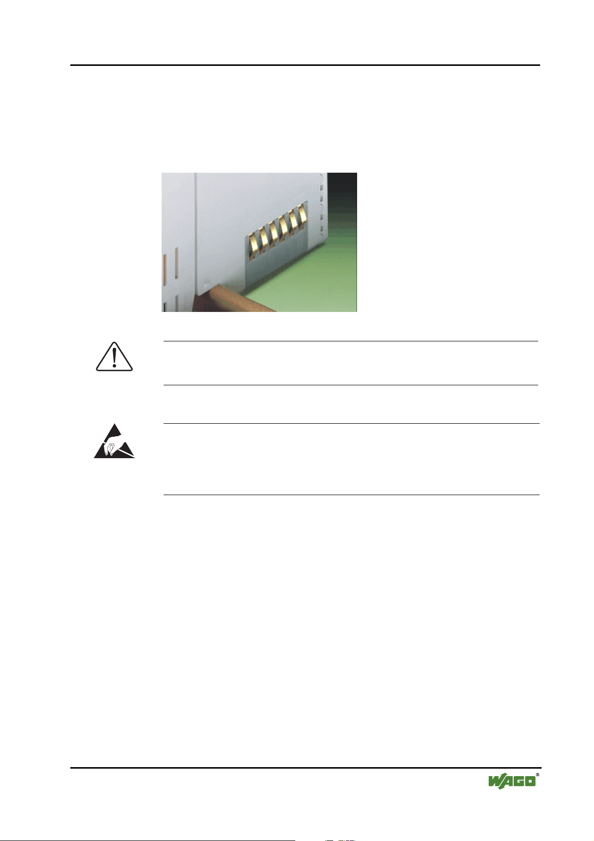
2.6.7 Internal Bus / Data Contacts
Communication between the ECO coupler and the bus modules as well as the
system supply of the bus modules is carried out via the internal bus. It is comprised of 6 data contacts, which are available as self-cleaning gold spring contacts.
Fig. 2-7: Data contacts p0xxx07x
Warning
Do not touch the gold spring contacts on the I/O modules in order to avoid
soiling or scratching!
ESD (Electrostatic Discharge)
The modules are equipped with electronic components that may be destroyed
by electrostatic discharge. When handling the modules, ensure that the environment (persons, workplace and packing) is well grounded. Avoid touching
conductive components, e.g. gold contacts.
WAGO-I/O-SYSTEM 750
DeviceNet
Page 24
24 • The WAGO-I/O-SYSTEM 750
Mechanical Setup
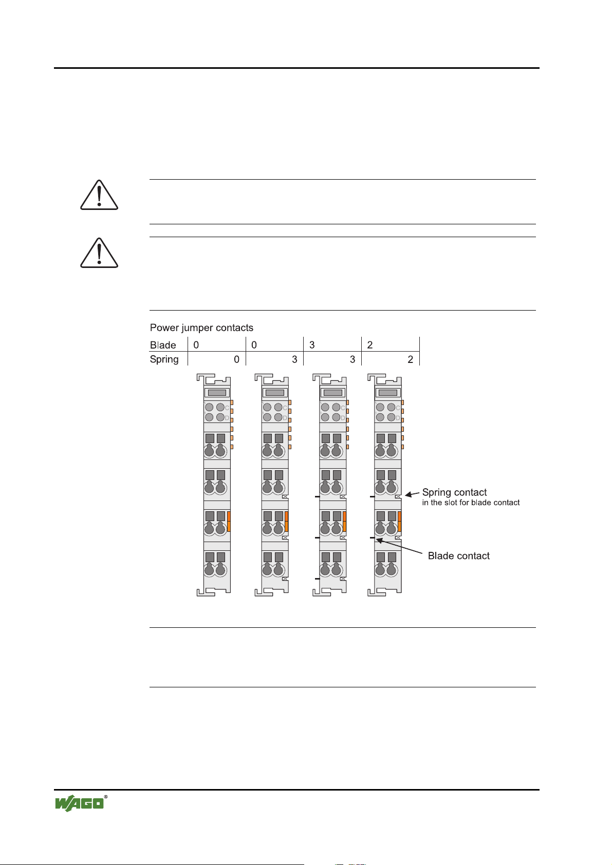
2.6.8 Power Contacts
Self-cleaning power contacts , are situated on the side of some components
which further conduct the supply voltage for the field side. These contacts
come as touchproof spring contacts on the right side of the bus modules. As
fitting counterparts the module has male contacts on the left side.
Danger
The power contacts are sharp-edged. Handle the module carefully to prevent
injury.
Attention
Please take into consideration that some bus modules have no or only a few
power jumper contacts. The design of some modules does not allow them to
be physically assembled in rows, as the grooves for the male contacts are
closed at the top.
Fig. 2-8: Example for the arrangement of power contacts g0xxx05e
Recommendation
With the WAGO ProServe® Software smartDESIGNER, the assembly of a
fieldbus node can be configured. The configuration can be tested via the integrated accuracy check.
WAGO-I/O-SYSTEM 750
DeviceNet
Page 25
The WAGO-I/O-SYSTEM 750 • 25
Mechanical Setup
2.6.9 Wire connection
All components have CAGE CLAMP® connections.
The WAGO CAGE CLAMP® connection is appropriate for solid, stranded
and fine–stranded conductors. Each clamping unit accommodates one conductor.
Fig. 2-9: CAGE CLAMP® Connection g0xxx08x
The operating tool is inserted into the opening above the connection. This
opens the CAGE CLAMP
®
. Subsequently the conductor can be inserted into
the opening. After removing the operating tool, the conductor is safely
clamped.
More than one conductor per connection is not permissible. If several conductors have to be made at one connection point, then they should be made away
from the connection point using WAGO Terminal Blocks. The terminal blocks
may be jumpered together and a single wire brought back to the I/O module
connection point.
Attention
If it is unavoidable to jointly connect 2 conductors, then a ferrule must be
used to join the wires together.
Ferrule:
Length 8 mm
Nominal cross section
1 mm2 for 2 conductors with 0.5 mm2
max.
each
WAGO Product 216-103
or products with comparable properties
WAGO-I/O-SYSTEM 750
DeviceNet
Page 26
26 • The WAGO-I/O-SYSTEM 750
Power Supply
2.7 Power Supply
2.7.1 Isolation
Within the fieldbus node, there are three electrically isolated potentials.
• Operational voltage for the fieldbus interface.
• Electronics of the ECO coupler and the bus modules (internal bus).
• All bus modules have an electrical isolation between the electronics (inter-
nal bus, logic) and the field electronics. Some analog input modules have
each channel electrically isolated, please see catalog.
Potential of the system supply
Electrical isolation
to the field level
T6,3 A
250 V
Fieldbus
Interface
DC
DC
Potential
Fieldbus interface
Fig. 2-10: Isolation g0xxx11e
Elektronic
Potentials
in the field level
per module
per channel
Attention
The ground wire connection must be present in each group. In order that all
protective conductor functions are maintained under all circumstances, it is
recommended that a ground wire be connected at the beginning and end of a
potential group. (ring format, please see chapter "2.8.3"). Thus, if a bus module comes loose from a composite during servicing, then the protective conductor connection is still guaranteed for all connected field devices.
When using a joint power supply unit for the 24 V system supply and the
24 V field supply, the electrical isolation between the internal bus and the
field level is eliminated for the potential group.
WAGO-I/O-SYSTEM 750
DeviceNet
Page 27
The WAGO-I/O-SYSTEM 750 • 27
Power Supply
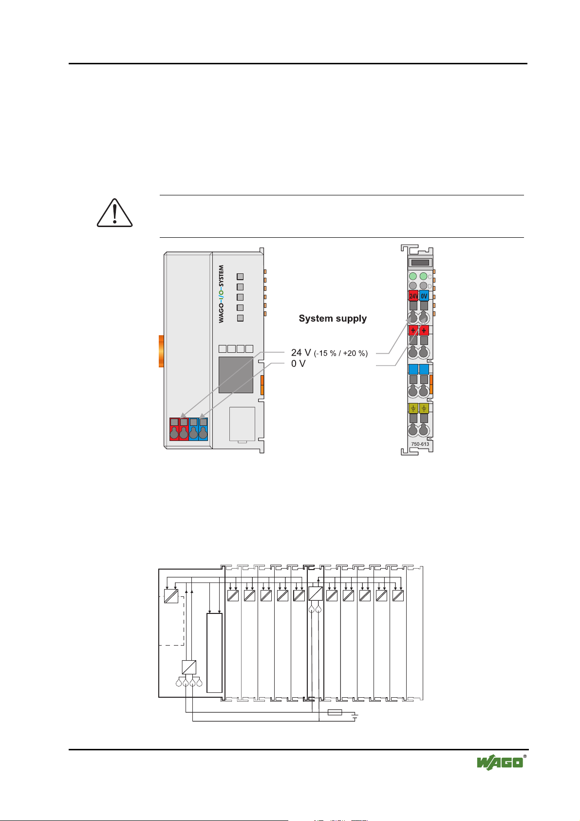
2.7.2 System Supply
2.7.2.1 Connection
The WAGO-I/O-SYSTEM 750 requires a 24 V direct current system supply
(-15% or +20 %). The power supply is provided via the ECO coupler and, if
necessary, in addition via the internal system supply modules (750-613). The
voltage supply is reverse voltage protected.
Attention
The use of an incorrect supply voltage or frequency can cause severe damage
to the component.
Fig. 2-11: System Supply g0xxx16e
The direct current supplies all internal system components, e.g. ECO coupler
electronics, fieldbus interface and bus modules via the internal bus (5 V system voltage). The 5 V system voltage is electrically connected to the 24 V system supply.
750-613750-343…346
DC5V
DC
DC
Fieldbus
Interface
DC
DC
Electronic
DC 24 V
(-15% / + 20%)
Fig. 2-12: System Voltage g0xxx12e
0V
WAGO-I/O-SYSTEM 750
DeviceNet
Page 28
28 • The WAGO-I/O-SYSTEM 750
Power Supply
Attention
Resetting the system by switching on and off the system supply, must take
place simultaneously for all supply modules (ECO coupler and 750-613).
2.7.2.2 Alignment
Recommendation
A stable network supply cannot be taken for granted always and everywhere.
Therefore, regulated power supply units should be used in order to guarantee
the quality of the supply voltage.
The supply capacity of the ECO coupler or the internal system supply module
(750-613) can be taken from the technical data of the components.
Internal current consumption*)
Residual current for bus terminals*)
*) cf. catalogue W4 Volume 3, manuals or Internet
Example ECO Coupler:
Current consumption via system voltage:
5 V for electronics of the bus modules and ECO
coupler
Available current for the bus modules. Provided by
the bus power supply unit. See ECO coupler and
internal system supply module (750-613)
internal current consumption:350 mA at 5V
residual current for
bus modules : 650 mA at 5V
sum I
: 1000 mA at 5V
(5V) total
The internal current consumption is indicated in the technical data for each bus
terminal. In order to determine the overall requirement, add together the values of all bus modules in the node.
Attention
If the sum of the internal current consumption exceeds the residual current for
bus modules, then an internal system supply module (750-613) must be
placed before the module where the permissible residual current was exceeded.
Example:
WAGO-I/O-SYSTEM 750
DeviceNet
A node with a PROFIBUS ECO Coupler consists of 10 relay modules
(750-517) and 20 digital input modules (750-405).
Current consumption:
10* 90 mA = 900 mA
20* 2 mA = 40 mA
Sum 940 mA
The ECO coupler can provide 650 mA for the bus modules. Consequently, an internal system supp ly module (750-613), e.g. in the middle of the node, should be added.
Page 29

The WAGO-I/O-SYSTEM 750 • 29
Power Supply
Recommendation
With the WAGO ProServe® Software smartDESIGNER, the assembly of a
fieldbus node can be configured. The configuration can be tested via the integrated accuracy check.
The maximum input current of the 24 V system supply is 260 mA. The exact
electrical consumption (I
ECO Coupler
I
750-613
I
= Sum of all the internal current consumption of the connected
(5 V) total
= Sum of all the internal current consumption of the connected
(5 V) total
) can be determined with the following formulas:
(24 V)
bus modules
+ internal current consumption coupler
bus modules
Input current I
(24 V)
=
5 V / 24 V * I
η = 0.80 (at nominal load)
(5 V) total
/ η
Note
If the electrical consumption of the power supply point for the 24 V-system
supply of the ECO coupler exceeds 260 mA or 500 mA for the 750-613, then
the cause may be an improperly aligned node or a defect.
During the test, all outputs, in particular those of the relay modules, must be
active.
WAGO-I/O-SYSTEM 750
DeviceNet
Page 30
30 • The WAGO-I/O-SYSTEM 750
Power Supply
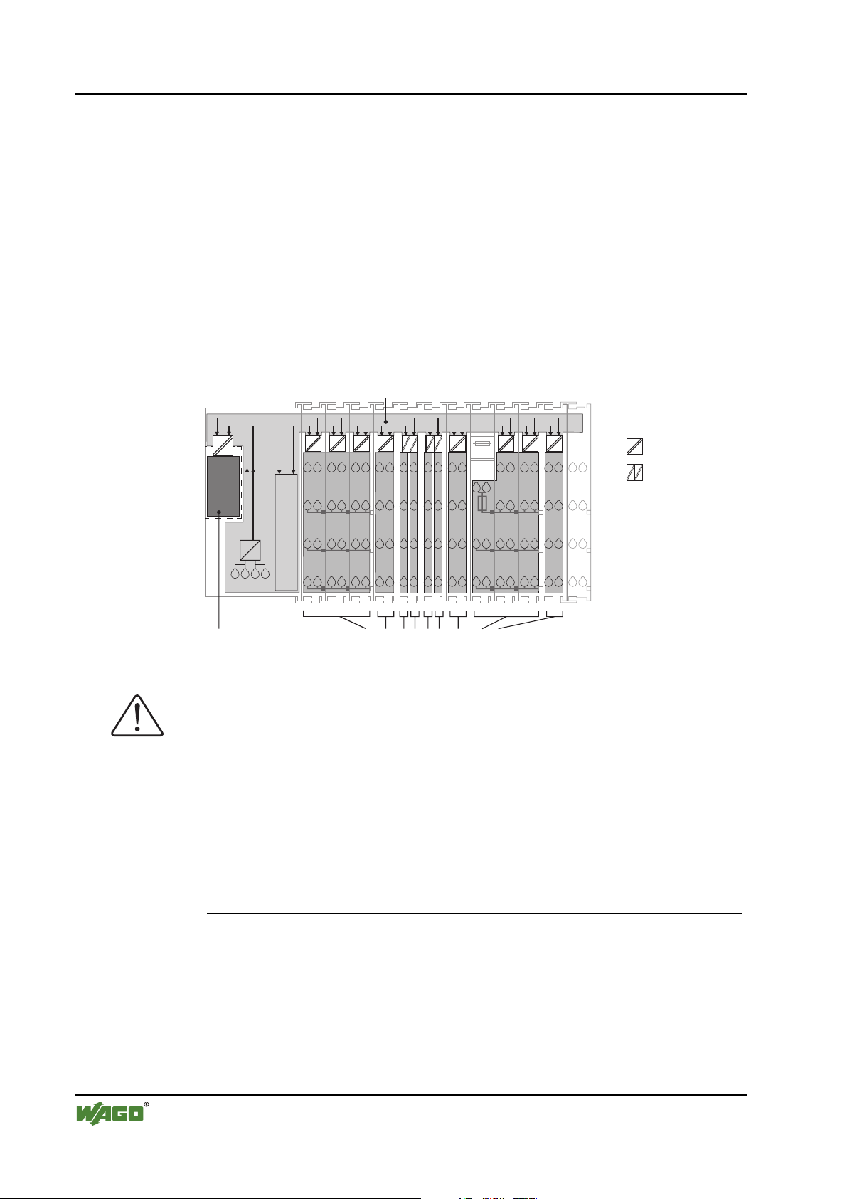
2.7.3 Field Supply
2.7.3.1 Connection
Sensors and actuators can be directly connected to the relevant channel of the
bus module in 1-/4 conductor connection technology. The bus module supplies
power to the sensors and actuators. The input and output drivers of some bus
modules require the field side supply voltage.
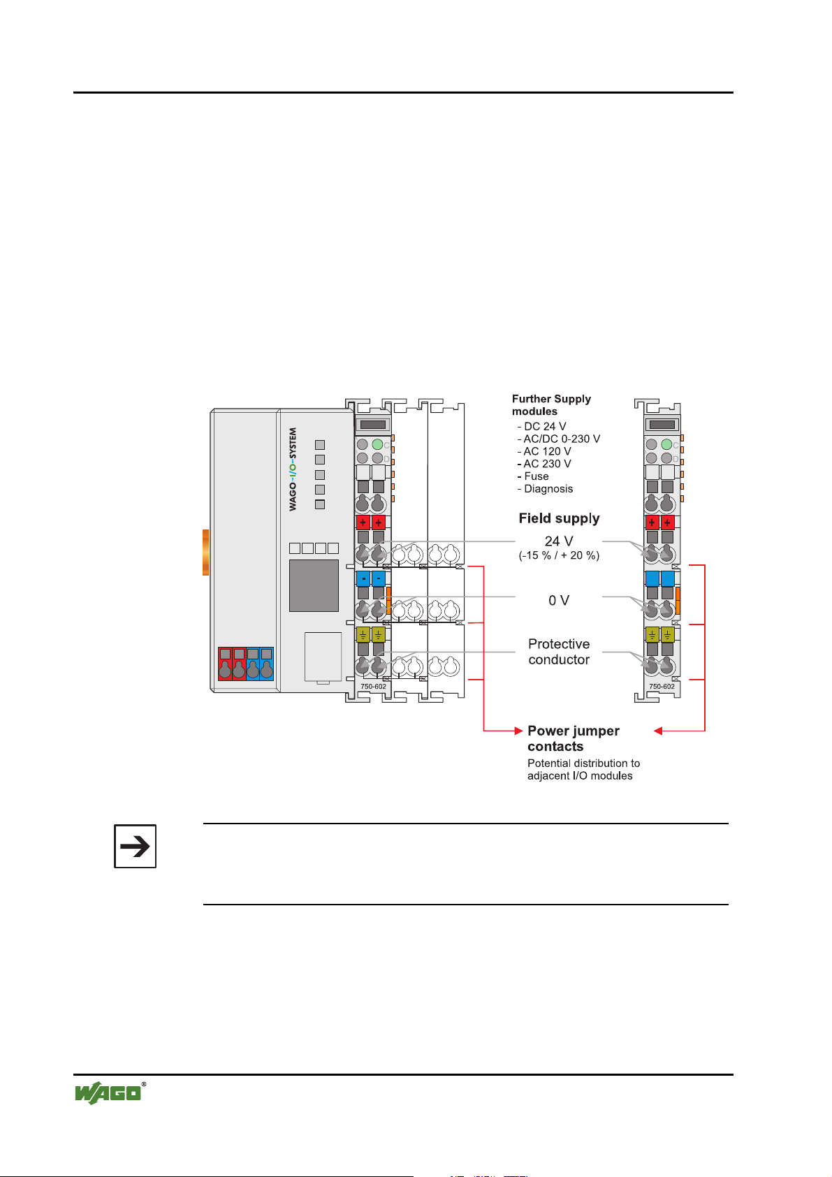
The power supply modules provide field side power (DC 24V). In this case it
is a passive power supply without protection equipment. Power supply modules are available for different potentials, e.g. DC 24 V, AC 230 V or others.
Likewise, with the aid of the power supply modules, various potentials can be
set up. The connections are linked in pairs with a power contact.
Fig. 2-13: Field Supply (Sensor / Actuator) g0xxx17e
Note
The 24 V field supply can be connected also directly to a bus module, if the
connection points are not needed for the peripheral device supply. In this
case, the connection points need the connection to the power jumper contacts
.
The supply voltage for the field side is automatically passed to the next module via the power jumper contacts when assembling the bus modules .
The current load of the power contacts must not exceed 10 A on a continual
basis. The current load capacity between two connection terminals is identical
to the load capacity of the connection wires.
WAGO-I/O-SYSTEM 750
DeviceNet
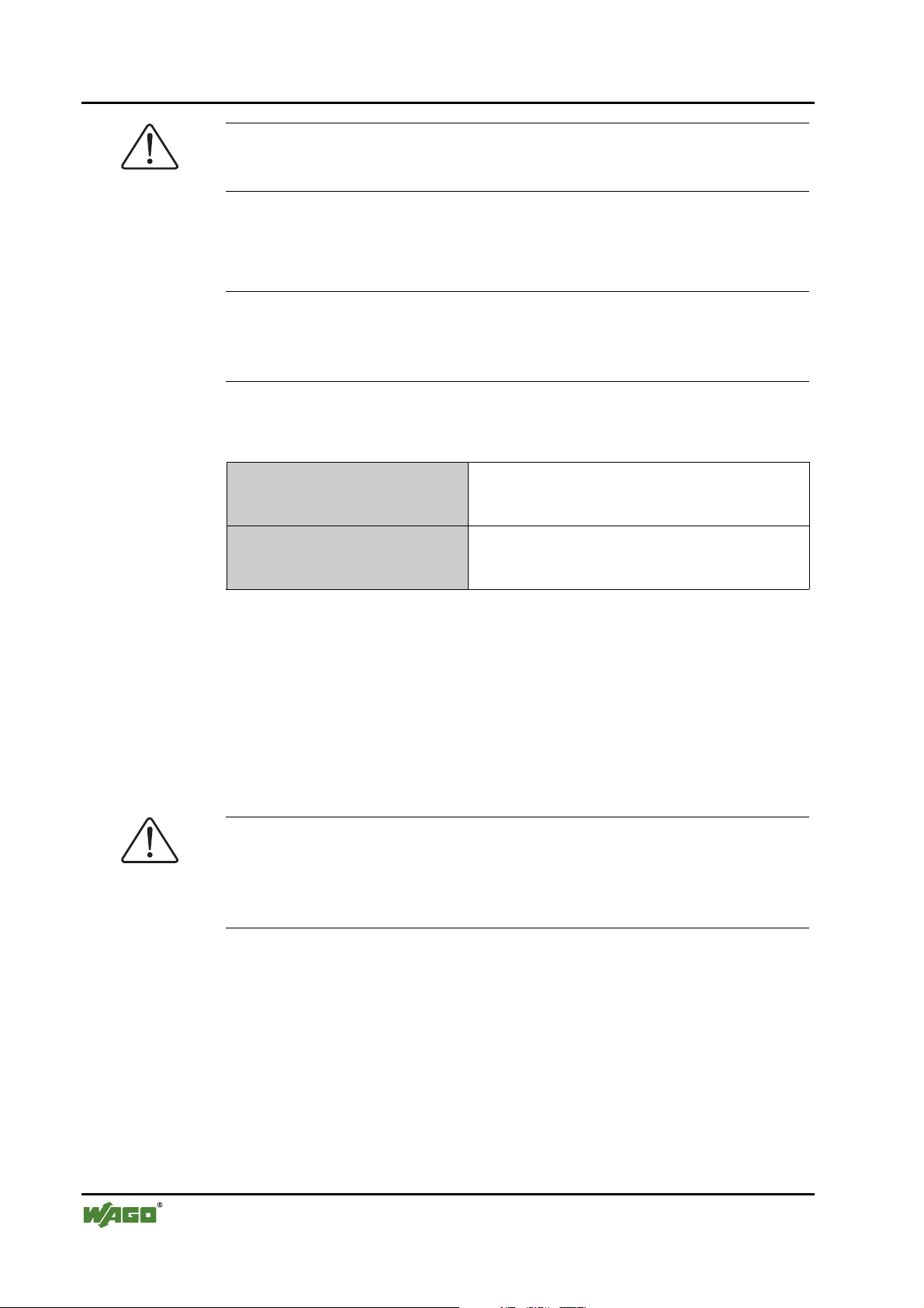
Page 31

The WAGO-I/O-SYSTEM 750 • 31
Power Supply
By inserting an additional power supply module, the field supply via the
power contacts is disrupted. From there a new power supply occurs which
may also contain a new voltage potential.
Attention
Some bus modules have no or very few power contacts (depending on the I/O
function). Due to this, the passing through of the relevant potential is disrupted. If a field supply is required for subsequent bus modules, then a power
supply module must be used.
Note the data sheets of the bus modules.
In the case of a node setup with different potentials, e.g. the alteration from
DC 24 V to AC 230V, a spacer module should be used. The optical separation of the potentials acts as a warning to heed caution in the case of wiring
and maintenance works. Thus, the results of wiring errors can be prevented.
2.7.3.2 Fusing
Internal fusing of the field supply is possible for various field voltages via an
appropriate power supply module.
750-601 24 V DC, Supply / Fuse
750-609 230 V AC, Supply / Fuse
750-615 120 V AC, Supply / Fuse
750-610 24 V DC, Supply / Fuse / Diagnosis
750-611 230 V AC, Supply / Fuse / Diagnosis
Fig. 2-14: Supply module with fuse carrier (Example 750-610) g0xxx09e
WAGO-I/O-SYSTEM 750
DeviceNet
Page 32

32 • The WAGO-I/O-SYSTEM 750
Power Supply
Warning
In the case of power supply modules with fuse holders, only fuses with a
maximum dissipation of 1.6 W (IEC 127) must be used.
For UL approved systems only use UL approved fuses.
In order to insert or change a fuse, or to switch off the voltage in succeeding
bus modules, the fuse holder may be pulled out. In order to do this, use a
screwdriver for example, to reach into one of the slits (one on both sides) and
pull out the holder.
Fig. 2-15: Removing the fuse carrier p0xxx05x
Lifting the cover to the side opens the fuse carrier.
Fig. 2-16: Opening the fuse carrier p0xxx03x
Fig. 2-17: Change fuse p0xxx04x
After changing the fuse, the fuse carrier is pushed back into its original position.
WAGO-I/O-SYSTEM 750
DeviceNet
Page 33

The WAGO-I/O-SYSTEM 750 • 33
Power Supply
Alternatively, fusing can be done externally. The fuse modules of the WAGO
series 281 and 282 are suitable for this purpose.
Fig. 2-18: Fuse modules for auto motive fuses, Series 282 pf66800x
Fig. 2-19: Fuse modules with pivotable fuse carrier , Se ri es 28 1 pe61100x
Fig. 2-20: Fuse modules, Series 282 pf12400x
WAGO-I/O-SYSTEM 750
DeviceNet
Page 34

34 • The WAGO-I/O-SYSTEM 750
Power Supply
2.7.4 Supply example
Note
The system supply and the field supply should be separated in order to ensure
bus operation in the event of a short-circuit on the actuator side.
L1
L2
L3
N
PE
1)
a)
b)
c)
1)
d)
System
Supply
Field
Supply
Field
Supply
230V
230V
24V
24V
10 A
750-613
2) 2)
10 A
750-512 750-512750-616 750-513 750-610 750-552 750-600750-612 750-616
750-630750-612 750-410 750-401
Shield (screen) bus
Main ground bus
1) Separation module
recommended
2) Ring-feeding
recommended
a) Power Supply
on coupler via external
Supply Module
b) Internal System
Supply Module
c) Supply Module
passive
d)
Supply Module
with fuse carrier/
iagnostics
d
Fig. 2-21: Supply example g0xxx13e
WAGO-I/O-SYSTEM 750
DeviceNet
Page 35

The WAGO-I/O-SYSTEM 750 • 35
Power Supply
2.7.5 Power Supply Unit
The WAGO-I/O-SYSTEM 750 requires a 24 V direct current system supply
with a maximum deviation of -15% or +20 %.
Recommendation
A stable network supply cannot be taken for granted always and everywhere.
Therefore, regulated power supply units should be used in order to guarantee
the quality of the supply voltage.
A buffer (200 µF per 1 A current load) should be provided for brief voltage
dips. The I/O system buffers for approx 1 ms.
The electrical requirement for the field supply is to be determined individually
for each power supply point. Thereby all loads through the field devices and
bus modules should be considered. The field supply as well influences the bus
modules, as the inputs and outputs of some bus modules require the voltage of
the field supply.
Note
The system supply and the field supply should be isolated from the power
supplies in order to ensure bus operation in the event of short circuits on the
actuator side.
WAGO products
Article No.
Description
787-903 Primary switched - mode, DC 24 V, 5 A
wide input voltage range AC 85-264 V
PFC (Power Factor Correction)
787-904 Primary switched - mode, DC 24 V, 10 A
wide input voltage range AC 85-264 V
PFC (Power Factor Correction)
787-912 Primary switched - mode, DC 24 V, 2 A
wide input voltage range AC 85-264 V
PFC (Power Factor Correction)
288-809
288-810
288-812
288-813
Rail-mounted modules with universal mounting carrier
AC 115 V / DC 24 V; 0,5 A
AC 230 V / DC 24 V; 0,5 A
AC 230 V / DC 24 V; 2 A
AC 115 V / DC 24 V; 2 A
WAGO-I/O-SYSTEM 750
DeviceNet
Page 36

36 • The WAGO-I/O-SYSTEM 750 Grounding
2.8 Grounding
2.8.1 Grounding the DIN Rail
2.8.1.1 Framework Assembly
When setting up the framework, the carrier rail must be screwed together with
the electrically conducting cabinet or housing frame. The framework or the
housing must be grounded. The electronic connection is established via the
screw. Thus, the carrier rail is grounded.
Attention
Care must be taken to ensure the flawless electrical connection between the
2.8.1.2 Insulated Assembly
carrier rail and the frame or housing in order to guarantee sufficient grounding.
Insulated assembly has been achieved when there is constructively no direct
conduction connection between the cabinet frame or machine parts and the
carrier rail. Here the earth must be set up via an electrical conductor.
The connected grounding conductor should have a cross section of at least
2
4 mm
.
Recommendation
The optimal insulated setup is a metallic assembly plate with grounding connection with an electrical conductive link with the carrier rail.
The separate grounding of the carrier rail can be easily set up with the aid of
the WAGO ground wire terminals.
Article No. Description
283-609 Single-conductor ground (earth) terminal block make an automatic
contact to the carrier rail; conductor cross section: 0.2 -16 mm2
Note: Also order the end and intermediate plate (283-320)
WAGO-I/O-SYSTEM 750
DeviceNet
Page 37

The WAGO-I/O-SYSTEM 750 • 37
Grounding
2.8.2 Grounding Function
The grounding function increases the resistance against disturbances from
electro-magnetic interferences. Some components in the I/O system have a
carrier rail contact that dissipates electro-magnetic disturbances to the carrier
rail.
Fig. 2-22: Carrier rail contact g0xxx10e
Attention
Care must be taken to ensure the direct electrical connection between the carrier rail contact and the carrier rail.
The carrier rail must be grounded.
For information on carrier rail properties, please see chapter 2.6.3.2.
WAGO-I/O-SYSTEM 750
DeviceNet
Page 38

38 • The WAGO-I/O-SYSTEM 750
Grounding
2.8.3 Grounding Protection
For the field side, the ground wire is connected to the lowest connection terminals of the power supply module. The ground connection is then connected
to the next module via the Power Jumper Contact (PJC). If the bus module has
the lower power jumper contact, then the ground wire connection of the field
devices can be directly connected to the lower connection terminals of the bus
module.
Attention
Should the ground conductor connection of the power jumper contacts within
the node become disrupted, e.g. due to a 4-channel bus terminal, the ground
connection will need to be re-established.
The ring feeding of the grounding potential will increase the system safety.
When one bus module is removed from the group, the grounding connection
will remain intact.
The ring feeding method has the grounding conductor connected to the beginning and end of each potential group.
Fig. 2-23: Ring-feeding g0xxx07e
Attention
The regulations relating to the place of assembly as well as the national regulations for maintenance and inspection of the grounding protection must be
observed.
WAGO-I/O-SYSTEM 750
DeviceNet
Page 39

The WAGO-I/O-SYSTEM 750 • 39 Shielding (Screening)
2.9 Shielding (Screening)
2.9.1 General
The shielding of the data and signal conductors reduces electromagnetic interferences thereby increasing the signal quality. Measurement errors, data
transmission errors and even disturbances caused by overvoltage can be
avoided.
Attention
Constant shielding is absolutely required in order to ensure the technical
specifications in terms of the measurement accuracy.
The data and signal conductors should be separated from all high-voltage
cables.
The cable shield should be potential. With this, incoming disturbances can be
easily diverted.
The shielding should be placed over the entrance of the cabinet or housing in
order to already repel disturbances at the entrance.
2.9.2 Bus Conductors
The shielding of the bus conductor is described in the relevant assembly
guideline of the bus system.
2.9.3 Signal Conductors
Bus modules for most analog signals along with many of the interface bus
modules include a connection for the shield.
Note
For better shield performance, the shield should have previously been placed
over a large area. The WAGO shield connection system is suggested for such
an application.
This suggestion is especially applicable when the equipment can have even
current or high impulse formed currents running through it (for example
through atmospheric end loading).
WAGO-I/O-SYSTEM 750
DeviceNet
Page 40

40 • The WAGO-I/O-SYSTEM 750 Assembly Guidelines / Standards
2.9.4 WAGO Shield (Screen) Connecting System
The WAGO Shield Connecting system includes a shield clamping saddle, a
collection of rails and a variety of mounting feet. Together these allow many
dfferent possibilities. See catalog W4 volume 3 chapter 10.
Fig. 2-24: WAGO Shield (Screen) Connecting System p0xxx08x, p0xxx09x, and p0xxx10x
Fig. 2-25: Application of the WAGO Shield (Screen) Connecting System p0xxx11x
2.10 Assembly Guidelines / Standards
DIN 60204, Electrical equipping of machines
DIN EN 50178 Equipping of high-voltage systems with electronic
components (replacement for VDE 0160)
EN 60439 Low voltage – switch box combinations
WAGO-I/O-SYSTEM 750
DeviceNet
Page 41

The WAGO-I/O-SYSTEM 750 • 41
Assembly Guidelines / Standards
WAGO-I/O-SYSTEM 750
DeviceNet
Page 42

42 • Fieldbus Coupler Fieldbus Coupler 750-346
3 Fieldbus Coupler
3.1 Fieldbus Coupler 750-346
This chapter includes:
3.1.1 Description.........................................................................................43
3.1.2 Hardware............................................................................................44
3.1.2.1 View..............................................................................................44
3.1.2.2 Device Supply...............................................................................45
3.1.2.3 Fieldbus Connection .....................................................................45
3.1.2.4 Display Elements ..........................................................................46
3.1.2.5 Configuration Interface.................................................................47
3.1.2.6 Hardware Address (MAC ID).......................................................47
3.1.2.7 Setting the Baud Rate....................................................................48
3.1.3 Operating System...............................................................................48
3.1.4 Process Image....................................................................................49
3.1.5 Data Exchange...................................................................................50
3.1.5.1 Communication Interfaces............................................................51
3.1.5.2 Memory Areas ..............................................................................51
3.1.5.3 Addressing ....................................................................................52
3.1.5.3.1 Fieldbus Specific...........................................................................52
3.1.6 Configuration Software .....................................................................54
3.1.7 Starting up DeviceNet Fieldbus Nodes..............................................54
3.1.7.1 Connecting the PC and Fieldbus Node .........................................54
3.1.7.2 Setting the MAC ID and Baud Rate .............................................54
3.1.7.3 Configuration with Static Assembly.............................................55
3.1.8 LED Display......................................................................................59
3.1.8.1 Node status – Blink code from the 'I/O' LED ...............................60
3.1.9 Technical Data...................................................................................67
WAGO-I/O-SYSTEM 750
DeviceNet
Page 43

Fieldbus Coupler • 43
Fieldbus Coupler 750-346
3.1.1 Description
The ECO fieldbus coupler is designed for applications with a reduced scale
I/O requirement. By using digital only process data, or small amounts of analog data, the ECO Fieldbus coupler retains all of the choices that are offered
by the Series 750 I/O.
The coupler has an integrated supply terminal for the system voltage. The field
power jumper contacts are supplied via a separate supply module.
The DeviceNet bus coupler is capable of supporting all I/O modules and automatically configures, creating a local process image.
DeviceNet allows the storing of the process image in the corresponding Master control (PLC, PC or NC).
The local process image is divided into two data zones containing the data received and the data to be sent.
The process data can be sent via the DeviceNet fieldbus to the PLC, PC or NC
for further processing, and received from the field via DeviceNet TM.
The data of the analog modules is stored in the process image which is created
automatically according to the order in which the modules are connected to the
buscoupler. The bits of the digital modules are sent byte by byte and added to
the analog data. If the amount of digital information exceeds 8 bits, the buscoupler automatically starts with a new byte.
WAGO-I/O-SYSTEM 750
DeviceNet
Page 44

44 • Fieldbus Coupler
Fieldbus Coupler 750-346
3.1.2 Hardware
3.1.2.1 View
Status indication
-Fieldbus
-Fieldbus node
Data contacts
DIP switch
for MAC ID
and baud rate
ON
12345678
01
02
DEVICENET
OVERFL
MS
RUN
BUS OFF
NS
750-346
CONNECT
I/O
04
03
Marking area
Fieldbus
connection
Series 231
(MCS)
Supply
24 V
Configuration
interface
0V
Fig. 3-1: ECO fieldbus coupler 750-3 46 De viceNet g034600e
The fieldbus coupler comprises of:
• Supply module with internal system supply module for the system supply
• Fieldbus interface with the bus connection
• Display elements (LED's) for status display of the operation, the bus com-
munication, the operating voltages as well as for fault messages and diagnosics
• Configuration interface
• Electronics for communication with the I/O modules (internal bus) and the
fieldbus interface
WAGO-I/O-SYSTEM 750
DeviceNet
Page 45

Fieldbus Coupler • 45
Fieldbus Coupler 750-346
3.1.2.2 Device Supply
The supply is made via terminal blocks with CAGE CLAMP® connection.
The device supply is intended for the system unit.
I/O Modules
1/2
24 V
0V
3/4
10 nF
24 V
5V
Electronic
Fieldbus
Interface
24 V 0 V
1234
750-346
Fig. 3-2: Device supply g034631e
The integrated internal system supply module generates the necessary voltage
to supply the electronics of the coupler and the connected I/O modules.
The fieldbus interface is supplied by the fieldbus.
3.1.2.3 Fieldbus Connection
For the field bus connection, the DeviceNet interface is equipped with a 5 pole
header, its counter-piece being a plug connector (Open Style Connector).
The scope of delivery includes the plug connector 231-305/010-000/050-000
from the WAGO MULTI CONNECTION SYSTEM. The connector has gold
plated contacts and has the signal designations printed at its clamping units.
Electronic
10 nF
24 V
5V
Fieldbus
Interface
1) 1M
2) 10nF/500V
1)
2)
The table below shows the connection diagram, the colors resulting in accordance with the DeviceNet specification and are identical to the conductor colors of the DeviceNet cables.
Pin Signal Code Description
5 V+ red 11 ... 25 V
Fieldbus connection
Series 231
(MCS)
Fig. 3-3: Fieldbus connection, MCS g012500e
WAGO-I/O-SYSTEM 750
DeviceNet
V+
4 CAN_H white CAN Signal
CAN_High
drain
3 Shield Shield connection
CAN_Low
V-
2 CAN_L blue CAN Signal
1 V- black 0 V
High
Low
Page 46

46 • Fieldbus Coupler
Fieldbus Coupler 750-346
For the connection of small conductor cross sections, we recommend to insert
an insulation stop from series 231-670 (white), 231-671 (light grey) or 231672 (dark grey) due to the low kink resistance. This insulation stop prevents a
conductor from kinking when it hits the conductor contact point, and as such
the conductor insulation from also being entered into and clamped in the connection point. Connector marking and housing components, test connectors
including cables and header connectors for cable extensions are available.
The connection point is lowered in such a way that after a connector is inserted, installation in an 80 mm high switchbox is possible.
The electrical isolation between the fieldbus system and the electronics is
made via the DC/DC converter and the optocoupler in the fieldbus.
3.1.2.4 Display Elements
The operating condition of the fieldbus coupler or node is signalled via light
diodes (LED).
Four LEDs specific for DeviceNet (OVERFL, RUN, BUSOFF, CONNECT)
indicate the module status (MS) and the network status (NS).
DEVICENET
OVERFL
MS
RUN
BUS OFF
NS
750-346
CONNECT
I/O
Fig. 3-4: Display elements 750-346 g034602x
LED Color Meaning
OVERFL red Errors or faults at the fieldbus coupler.
RUN green Fieldbus coupler is ready for ope rat ion.
BUS OFF red Error or malfunction at network
CONNECT green Fieldbus coupler is ready for network communication.
I/O red/
green/
orange
The ‚I/O‘-LED indicates the operation of the node and signals faults
encountered.
WAGO-I/O-SYSTEM 750
DeviceNet
Page 47

Fieldbus Coupler • 47
Fieldbus Coupler 750-346
3.1.2.5 Configuration Interface
The configuration interface used for the communication with
WAGO-I/O-CHECK or for firmware transfer is located behind the cover flap.
open
flap
Configuration interface
Fig. 3-5: Configuration interface g01xx06e
The communication cable (750-920) is connected to the 4 pole header.
Warning
The communication cable 750-920 must not be connected or disconnected
while the coupler/controller is powered on!
3.1.2.6 Hardware Address (MAC ID)
The DIP switch is used both for parametrizing (setting the baud rate) of the
fieldbus coupler and for setting the MAC ID.
The MAC-ID (node address) is set with the DIP switches 1 to 6 by 'sliding' the
desired DIP switch to 'ON'.
The binary significance of the individual DIP switches increases according to
the switch number. DIP switch 1 being the lowest bit with the value 2
switch 6 the highest bit with the value 2
DIP1 = ON, the MAC ID 8 with DIP4 = ON, etc.
For the DeviceNet fieldbus nodes the node address can be set within the range
from 0 to 63.
8
8
7
67
6
ON
ON
Fig. 3-6: Example: Setting of station (node) address MAC ID 1 (DIP 1 = ON) g012548x
5
4
345
3
2
12
1
0
5
. Therefore the MAC ID 1 is set with
and
The configuration is only read during the power up sequence. Changing the
switch position during operation does not change the configuration of the buscoupler. Turn off and on the power supply for the fieldbus coupler to accept
the DIP switch change.
The default setting is MAC ID 1.
WAGO-I/O-SYSTEM 750
DeviceNet
Page 48

48 • Fieldbus Coupler
Fieldbus Coupler 750-346
3.1.2.7 Setting the Baud Rate
The bus coupler supports 3 different Baud rates, 125 kBaud, 250 kBaud and
500 kBaud. DIP switches 7 and 8 are used to set the baud rate.
8
8
7
67
6
ON
ON
g012549x
Fig. 3-7: Example: Setting the baud
rate 250 kBaud (DIP 7 = ON) on a
station (node) with the address MAC
ID 1.
5
4
345
3
2
12
1
The configuration is only read during the power up sequence. Changing the
switch position during operation does not change the configuration of the buscoupler. Turn off and on the power supply for the fieldbus coupler to accept
the DIP switch change.
Baudrate DIP7 DIP8
125 kBaud*) OFF OFF
250 kBaud ON OFF
500 kBaud OFF ON
not allowed ON ON
*)
Presetting
The default setting is Baud rate 125 kB.
3.1.3 Operating System
Following is the configuration of the master activation and the electrical installation of the fieldbus station.
After switching on the supply voltage, the coupler performs a self test of all
functions of its devices, the I/O module and the fieldbus interface. Following
this the I/O modules and the present configuration is determined, whereby an
external not visible list is generated.
In the event of a fault the coupler changes to the "Stop" condition. The "I/O"
LED flashes red. After clearing the fault and cycling power, the coupler
changes to the "Fieldbus start" status and the "I/O" LED lights up green.
Fig. 3-8: Operating system - Power on g012113e
WAGO-I/O-SYSTEM 750
DeviceNet
Page 49

Fieldbus Coupler • 49
Fieldbus Coupler 750-346
3.1.4 Process Image
After powering up, the coupler recognizes all I/O modules plugged into the
node which supply or wait for data (data width/bit width > 0). In the nodes
analog and digital I/O modules can be mixed.
The coupler produces an internal process image from the data width and the
type of I/O module as well as the position of the I/O modules in the node. It is
divided into an input and an output data area.
The data of the digital I/O modules is bit orientated, i.e. the data exchange is
made bit for bit. The analog I/O modules are all byte orientated I/O modules,
i.e. modules where the data exchange is made byte for byte. These I/O modules include for example the counter modules, I/O modules for angle and path
measurement as well as the communication modules.
Note
For the number of input and output bits or bytes of the individual I/O modules
please refer to the corresponding I/O module description.
The data of the I/O modules is separated for the local input and output process
image in the sequence of their position after the coupler in the individual process image.
In the respective I/O area, analog modules are mapped first, then all digital
modules, even if the order of the connected analog and digital modules does
not comply with this order. The digital channels are grouped, each of these
groups having a data width of 1 byte. Should the number of digital I/Os exceed 8 bits, the coupler automatically starts another byte.
Note
A process image restructuring may result if a node is changed or extended. In
this case the process data addresses also change in comparison with earlier
ones. In the event of adding a module, take the process data of all previous
modules into account.
WAGO-I/O-SYSTEM 750
DeviceNet
Page 50

50 • Fieldbus Coupler
Fieldbus Coupler 750-346
3.1.5 Data Exchange
With DeviceNet, the transmission and exchange of data is made using objects.
For a network access on the single objects of the coupler, it is necessary to
create a connection between the desired participants and to allocate connection
objects.
For an easy and quick set-up of a connection the DeviceNet fieldbus coupler
750-346 uses the "Predefined Master/Slave Connection Set", which contains 4
pre-defined connections. For the access on the coupler the connections only
need to be allocated. The "Predefined Master/Slave Connection Set" confines
itself to pure Master/Slave relationships.
The DeviceNet fieldbus coupler 750-346 can only communicate via its assigned client and it is a so-called "Group 2 Only Server". The Group 2 Only
Server communicating is only possible via the Group 2 Only Unconnected
Explicit Message Port. These slaves exclusively receive messages defined in
message group 2.
The object configuration for the data transmission is defined by an Assembly
Object. The Assembly Object can be used to group data (e.g. I/O data) into
blocks (mapping) and send this data via one single communication connection.
This mapping results in a reduced number of accesses to the network.
A differentiation is made between "Input-Assemblies" and "OutputAssemblies".
An Input-Assembly reads in data from the application via the network or produces data on the network respectively.
An Output-Assembly writes data to the application or consumes data from the
network respectively.
Various Assembly instances are permanently programmed (static assembly) in
the fieldbus coupler.
Further information
The Assembly instances for the static assembly are described in chapter
"4.5.1.1Assembly Instance".
WAGO-I/O-SYSTEM 750
DeviceNet
Page 51

Fieldbus Coupler • 51
Fieldbus Coupler 750-346
3.1.5.1 Communication Interfaces
For a data exchange, the DeviceNet fieldbus coupler is equipped with two interfaces:
• the interface to fieldbus (-master) and
• the interface to the bus modules.
Data exchange takes place between the fieldbus master and the bus modules.
Access from the fieldbus side is fieldbus specific.
3.1.5.2 Memory Areas
The coupler uses a memory space of 32 bytes for the physical input and 32
bytes for the physical output data.
fieldbus coupler
fieldbus
Fig. 3-9: Memory areas and data exchange for a fieldbus coupler g012447e
memory area
for input data
input
modules
memory area
for output data
output
modules
1
2
I/O modules
I
O
The coupler process image contains the physical data of the bus modules in a
storage area for input data and in a storage area for output data (32 bytes each).
1 The input module data can be read from the fieldbus side.
2 In the same manner, writing to the output modules is possible from the
fieldbus side.
WAGO-I/O-SYSTEM 750
DeviceNet
Page 52

52 • Fieldbus Coupler
Fieldbus Coupler 750-346
3.1.5.3 Addressing
3.1.5.3.1 Fieldbus Specific
Once the supply voltage is applied, the Assembly Object maps data from the
process image. As soon as a connection is established, a DeviceNet-Master
(Scanner) can address and access the data by "Class", "Instance" and "Attribute".
Data mapping depends on the selected Assembly Instance of the static Assembly.
Further information
The Assembly Instances of the static Assembly are described in chapter
"4.5.1.1 Assembly Instance".
Fieldbus coupler
memory area
for input data
1
I/O modules
Connection
Object
Producer
Assembly
Object
Input-
Assemly
Application
Object
input
modules
fieldbus
master
Consumer
Output-
Assemly
Fig. 3-1: Fieldbus specific data exchange for a DeviceNet fieldbus coupler g012547e
Note
For the number of input and output bits or bytes of the individual I/O modules,
please refer to the corresponding I/O module description.
memory area
for output data
output
modules
2
I
O
Note
A process image restructuring may result if a node is changed or extended. In
this case the process data addresses also change in comparison with earlier
ones. In the event of adding a module, take the process data of all previous
modules into account.
WAGO-I/O-SYSTEM 750
DeviceNet
Page 53

Fieldbus Coupler • 53
Fieldbus Coupler 750-346
Example for static assembly (default assembly):
The default assembly is:
Output1 (I/O Assembly Instance 1)
Input1 (I/O Assembly Instance 4)
In this example, the fieldbus node arrangement looks like this:
1) 1 ECO fieldbus coupler DeviceNet (750-346),
2) 1 digital 4-channel input modules (i. e. 750-402),
3) 1 digital 4- channel output module (i. e. 750-504),
4) 1 analog 2- channel output module with 2 bytes per channel
(i. e. 750-552),
5) 1 analog 2- channel input module with 2 bytes per channel
(i. e. 750-456),
6) 1 End module (750-600).
Input process image:
Default process data, input image (Assembly Class, Instance 4)
Byte .7 .6 .5 .4 .3 .2 .1 .0
0
1
2
3
4
5
1)
DI = = Digital Input
2)
CS = Coupler Status (The last byte in the input process image is the Status Byte
of the Coupler, CS01...CS08, see also Object 0x64, Instance 1, Attribute 5)
CS01 =1: internal bus error (0x01)
CS02 =1: module communication error (0x02)
CS04 =1: module diagnostic (0x08)
CS08 =1: fieldbus error (0x80)
CS08 2) CS07 2) CS06 2) CS05 2) CS04 2) CS03 2) CS02 2) CS01 2)
not used DI041) DI031) DI021) DI011)
low byte channel 1
high byte channel 1
low byte channel 2
high byte channel 2
Output process image:
Default process data, output image (Assembly Class, Instance 1)
Byte .7 .6 .5 .4 .3 .2 .1 .0
0
1
2
3
4
1)
DO = Digital Output
not used DO041) DO031) DO021) DO011)
low byte channel 1
high byte channel 1
low byte channel 2
high byte channel 2
WAGO-I/O-SYSTEM 750
DeviceNet
Page 54

54 • Fieldbus Coupler
Fieldbus Coupler 750-346
3.1.6 Configuration Software
To enable a connection between the PLC and the fieldbus devices, the interface modules have to be configured with the individual station data.
To this effect, the scope of delivery of WAGO-I/O-SYSTEM 758 includes the
WAGO NETCON software intended for design and configuration, start-up and
diagnosis.
Further configuration software of different manufacturers include, for instance, RSNetWorx.
3.1.7 Starting up DeviceNet Fieldbus Nodes
This chapter shows the step-by-step procedure for starting up a
WAGO DeviceNet fieldbus node.
Attention
This description is given as an example and is limited to the execution of a
local start-up of an individual DeviceNet fieldbus node.
The procedure contains the following steps:
1. Connecting the PC and fieldbus node
2. Setting the MAC ID and baud rate
Configuration with static Assembly
3.1.7.1 Connecting the PC and Fieldbus Node
1. Connect the fitted DeviceNet fieldbus node to the DeviceNet fieldbus PCB in
your PC via a fieldbus cable.
The 24 V field bus supply is fed by an external fieldbus network power supply
over the connections V+, V- of the 5-pin fieldbus connector (MCS Series 231).
2. Start your PC.
3.1.7.2 Setting the MAC ID and Baud Rate
3. Use the DIP switches 1...6 to set the desired node address (MAC ID). The binary significance of the individual DIP switches increases according to the switch
number.
8
8
7
67
6
ON
ON
Fig. 3-10: Example: Setting the
MAC ID 4 (DIP 3 = ON).
5
4
345
3
2
12
1
g012550x
DIP switch Value
0
1
2
3
4
5
6
2
1
2
2
2
3
2
4
2
5
2
WAGO-I/O-SYSTEM 750
DeviceNet
Page 55

Fieldbus Coupler • 55
Fieldbus Coupler 750-346
4. DIP switches 7 and 8 are used to set the desired baud rate.
8
8
7
67
6
ON
ON
5
4
345
3
2
12
1
g012551x
Fig. 3-11: Example: Setting the baud
rate 250 kBaud (DIP 7 = ON) of the
station with MAC ID 1.
5. Then switch on the coupler supply voltage.
3.1.7.3 Configuration with Static Assembly
In this example, the software WAGO NETCON is used for the configuration.
The node in the example consists of the following I/O modules:
1234 5 67
DI DI
DODO
8
7
6
5
4
3
2
ON
1
DODO
DODO
AI AI
Baud rate DIP7 DIP8
125 kBaud*) OFF OFF
250 kBaud ON OFF
500 kBaud OFF ON
not allowed ON ON
*)
Presetting
AO AO
402 516
516
516 467
550 600
Fig. 3.1.7-12 Example Fieldbus node g012554x
1. Starting Software and EDS file load
6. Start the configuration software WAGO NETCON.
7. Load an EDS file for the fieldbus coupler in WAGO NETCON, i. e. "750-
346.EDS".
For this click on "File/ Copy EDS" and choose the EDS-file to load.
Note
You can download the EDS files for the fieldbus coupler from the Internet
under: www.wago.com.
8. Upon downloading the EDS file into WAGO NETCON, you can create a new
project and start configuring your network.
WAGO-I/O-SYSTEM 750
DeviceNet
Page 56

56 • Fieldbus Coupler
Fieldbus Coupler 750-346
2. Create a New Project
1. Enter the "File" menu and click on menu point "New".
2. Select "DeviceNet" as the fieldbus system and confirm your selection by
clicking on the "OK" button.
Fig. 3-13: Select fieldbus p112501d
3. Enter Master
1. Enter a fieldbus master on the surface by clicking on the „Master“ menu
point in the "Insert" menu.
A dialog window opens in which you can select the DeviceNet fieldbus card
in your PC.
Fig. 3-14: Select the DeviceNet fieldbus PCB / Insert Master p112502d
2. For the DeviceNet Master interface card, click in the left-hand selection
window on the corresponding entry to mark it.
3. Take the Master into the right-hand window by clicking on the "Add" button and confirm by clicking on the "OK" button.
Now the fieldbus master is shown on the surface as a graphic.
WAGO-I/O-SYSTEM 750
DeviceNet
Page 57

Fieldbus Coupler • 57
Fieldbus Coupler 750-346
4. Add a Slave
1. Enter a fieldbus slave on the surface by clicking on the “Device” menu
point in the "Insert" menu.
The mouse pointer changes to the letter D with an arrow.
2. Move this mouse pointer to the graphic display of the fieldbus, then click
on the left-hand mouse key.
A dialog window opens permitting you to select a DeviceNet device.
Fig.
3-15: Insert slave
g012503d
3. For the fieldbus coupler 750-346 click in the left-hand selection window on
the corresponding entry to mark it.
4. Take this into the right-hand window by clicking on the "Add" button and
confirm by clicking on the "OK" button.
The configuration is displayed on the surface as a graphic.
Fig. 3-16: Configuration p012504d
WAGO-I/O-SYSTEM 750
DeviceNet
Page 58

58 • Fieldbus Coupler
Fieldbus Coupler 750-346
5. Device Configuration
1. To configure the device, click on its graphic to mark it, then click on the
menu point “Device configuration” in the "Settings" menu.
A dialog window opens permitting you to proceed with the desired settings.
Fig. 3-17: Device Configuration p012506d
6. Load Configuration
1. To load the set configuration in the interface card, click on the master’s
graphic to mark it, then click on the “Download” menu point in the "Online" menu.
WAGO-I/O-SYSTEM 750
DeviceNet
Page 59

Fieldbus Coupler • 59
Fieldbus Coupler 750-346
3.1.8 LED Display
The coupler possesses several LEDs for on site display of the coupler operating status or the complete node.
DEVICENET
OVERFL
MS
RUN
BUS OFF
NS
750-346
CONNECT
I/O
Fig. 3-18: Display elements 750-346 g034602x
The module status (MS) and the network status (NS) can be displayed by the
top 4 LED’s. They react as described in the table.
Module status
OVERFL
(red)
off off no power No power supply to the device.
off on device operational The device operates correctly.
off blinking device in standby The device needs to be configured or has been partly
blinking off minor fault A minor fault has occurred. It exists a diagnostics.
on off unrecoverable fault The device is defective, needs to be serviced or
blinking blinking device self testing The device performs a built-in check.
RUN
(green)
State of device Meaning
configured.
replaced.
Table 3-1: Fault and status displays: MS
Network status
BUSOFF
(red)
off off not powered, not online No power supply to the device / fieldbus supply /
off blinking online, not connected The device operates correctly at the fieldbus. How-
off on link ok online, con-
blinking off connection time out A minor fault has occurred.
on off critical link failure The device has detected a fault. It is unable to per-
CONNECT
(green)
State of device Meaning
DeviceNet cable not connected and „Duplicate MAC
ID detection“ is not yet completed.
ever, it has not yet been integrated by a scanner.
nected
The device operates correctly at the fieldbus. At
least one connection to another device has been
established.
form any more functions in the network.
Table 3-2: Fault and status displays: NS
WAGO-I/O-SYSTEM 750
DeviceNet
Page 60

60 • Fieldbus Coupler
Fieldbus Coupler 750-346
3.1.8.1 Node status – Blink code from the 'I/O' LED
LED Color Meaning
IO red /green
/ orange
The 'I/O' LED indicates the node operation and signals faults occurring.
The coupler starts up after switching on the supply voltage. The "I/O" LED
blinks. The "I/O" LED has a steady light following a fault free start-up.
In the case of a fault the "I/O" LED continues blinking. The fault is cyclically
displayed by the blink code.
Detailed fault messages are displayed with the aid of a blink code. A fault is
cyclically displayed with up to 3 blink sequences.
• The first blink sequence (approx. 10 Hz) starts the fault display.
• The second blink sequence (approx. 1 Hz) following a pause. The
number of blink pulses indicates the fault code.
• The third blink sequence (approx. 1 Hz) follows after a further pause.
The number of blink pulses indicates the fault argument.
Fig. 3-19: Signalling the LED's node status g012111e
After overcoming a fault, restart the coupler by cycling the power.
WAGO-I/O-SYSTEM 750
DeviceNet
Page 61

Fieldbus Coupler • 61
Fieldbus Coupler 750-346
I/O Meaning
green Data cycle on the internal bus
off No data cycle on the internal bus
red Coupler hardware defective
red
blinks
red
blinks cyclically
When starting: internal bus is initialized
During operation: general internal bus fault
Fault message during internal bus reset and internal fault:
Fault message of the ‘I/O‘-LED
1 st flash sequence: Start of the Fault message
2 nd flash sequence: Fault code
3 rd flash sequence: Fault argument
Fault code 1: "Hardware and Configuration fault"
Fault argument Fault description Trouble shooting
1 Overflow of the internal buffer
memory for the inline code
2 I/O module(s) with unsupported
data type
3 Invalid EEPROM checksum Turn off the power supply of the
Turn off the power supply of the
node, reduce number of I/O modules and turn the power supply on
again. If the error still exists,
exchange the bus coupler.
Detect faulty I/O module as follows: turn off the power supply.
Place the end module in the middle of the fieldbus node. Turn the
power supply on again.
– If the LED is still blinking, turn
off the power supply and place the
end module in the middle of th e
first half of the node (towards the
coupler).
– If the LED doesn’t blink, turn
off the power supply and place the
end module in the middle of th e
second half of the node (away
from the coupler).
Turn the power supply on again.
Repeat this procedure until the
faulty I/O module is detected.
Replace the faulty I/O module.
Ask about a firmware update for
the fieldbus coupler.
node, reduce number of I/O modules and turn the power supply on
again
4 Error occurred when writing to
serial EEPROM
WAGO-I/O-SYSTEM 750
DeviceNet
Turn off the power supply of the
node, exchange fieldbus coupler
and turn the power supply on
again.
Page 62

62 • Fieldbus Coupler
Fieldbus Coupler 750-346
5 Error occurred with read access
to serial EEPROM
6 Changed I/O module configura-
tion determined after
AUTORESET
7 Firmware does not run on exist-
ing hardware
8 Time limit exceeded for access-
ing the serial EEPROM
14 Maximum number of Gateway or
Mailbox I/O modules exceeded
Fault code 2 -Process Image Fault -
Fault argument Fault description Trouble shooting
1 Process image not activ Access on invalid process image.
Turn off the power supply of the
node, exchange fieldbus coupler
and turn the power supply on
again.
Restart the fieldbus coupler by
turning the power supply off and
on again.
Turn off the power supply of the
node, exchange fieldbus coupler
and turn the power supply on
again.
Turn off the power supply of the
node, exchange fieldbus coupler
and turn the power supply on
again.
Turn off the power supply of the
node, reduce number of Gateway
or Mailbox I/O modules and turn
the power supply on again.
Please contact the WAGO I/OSupport (Note the version number
and the configuration)
2 Prozess image is larger than size
of buffer
3 Prozess image is zero Please contact the WAGO I/O-
Reduce the number of I/O modules
Support (Note the version number
and the configuration)
WAGO-I/O-SYSTEM 750
DeviceNet
Page 63

Fieldbus Coupler • 63
Fieldbus Coupler 750-346
Fault code 3: "Internal bus protocol fault"
Fault argument Fault description Trouble shooting
- Internal bus communication
malfunction; faulty device can’t
be detected
If the fieldbus node comprises
internal system supply modules
(750-613), make sure first that the
power supply of these modules is
functioning. This is indicated by
the status LEDs. If all I/O modules
are connected correctly or if the
fieldbus node doesn’t comprise
750-613 modules you can detect
the faulty I/O module as follows:
turn off the power supply of the
node. Place the end module in the
middle of the fieldbus node. Turn
the power supply on again.
– If the LED is still blinking, turn
off the power supply and place the
end module in the middle of th e
first half of the node (towards the
coupler).
– If the LED doesn’t blink, turn off
the power supply and place the end
module in the middle of the second
half of the node (away from the
coupler).
Turn the power supply on again.
Repeat this procedure until the
faulty I/O module is detected.
Replace the faulty I/O module. If
there is only one I/O module left
but the LED is still blinking, then
this I/O module or the coupler is
defective. Replace defective component.
WAGO-I/O-SYSTEM 750
DeviceNet
Page 64

64 • Fieldbus Coupler
Fieldbus Coupler 750-346
Fault code 4: "Internal bus physical fault"
Fault argument Fault description Trouble shooting
- Error in internal bus data communication or interruption of the
internal bus at the coupler
Turn off the power supply of the
node. Place an I/O module with
process data behind the coupler
and note the error argument after
the power supply is turned on. If
no error argument is given by the
I/O LED, replace the coupler.
Otherwise detect faulty I/O module
as follows: turn off the power
supply. Place the end module in
the middle of the fieldbus node.
Turn the power supply on again.
– If the LED is still blinking, turn
off the power supply and place the
end module in the middle of th e
first half of the node (towards the
coupler).
– If the LED doesn’t blink, turn off
the power supply and place the end
module in the middle of the second
half of the node (away from the
coupler).
Turn the power supply on again.
Repeat this procedure until the
faulty I/O module is detected.
Replace the faulty I/O module.
If there is only one I/O module left
but the LED is still blinking, then
this I/O module or the coupler is
defective. Replace defective component.
n* Interruption of the internal bus
after the n
th
process data module.
Turn off the power supply of the
node, exchange the (n+1)th process
data module and turn the power
supply on again.
WAGO-I/O-SYSTEM 750
DeviceNet
Page 65

Fieldbus Coupler • 65
Fieldbus Coupler 750-346
Fault code 5: "Internal bus initialization fault"
Fault argument Fault description Trouble shooting
n* Error in register communication
during internal bus initialization
Turn off the power supply of the
node and replace n
module and turn the power supply
on again.
Fault code 6 –Node configuration faultFault argument Fault description Trouble shooting
- Number of I/O modules is exceeded,
Reduce the number of I/O modules on the node
the Process image is bigger than
the available cache
Fault code 7 -not usedFault argument Fault description Trouble shooting
- not used -
Fault code 8 -not usedFault argument Fault description Trouble shooting
- not used -
Fault code 9 -not usedFault argument Fault description Trouble shooting
th
process data
- not used -
Fault code 10 -not usedFault argument Fault description Trouble shooting
- not used -
Fault code 11: "Gateway-/Mailbox I/O module fault"
Fault argument Fault description Trouble shooting
1
Maximum number of Gateway
modules exceeded
Turn off the power supply of the
node, reduce number of Gateway
modules and turn the power supply
on again.
2
Maximum size of Mailbox ex-
Reduce the Mailbox size.
ceeded
3
Maximum size of process image
exceeded due to the put Gateway
Reduce the data width of the
Gateway modules.
modules
* The number of blink pulses (n) indicates the position of the I/O module. I/O modules
without data are not counted (e.g. supply module without diagnosis)
WAGO-I/O-SYSTEM 750
DeviceNet
Page 66

66 • Fieldbus Coupler
Fieldbus Coupler 750-346
Example for a fault message; Fault: The 13th I/O module has been removed
1. The "I/O" LED starts the fault display with the first blink sequence (approx. 10
flashes/second).
2. The second blink sequence (1 flash/second) follows the first pause. The "I/O" LED
blinks four times and thus signals the fault code 4 (internal bus data fault).
3. The third blink sequence follows the second pause. The "I/O " LED blinks twelve
times. The fault argument 12 means that the internal bus is interrupted after the 12th
I/O module.
WAGO-I/O-SYSTEM 750
DeviceNet
Page 67

Fieldbus Coupler • 67
Fieldbus Coupler 750-346
3.1.9 Technical Data
System data
Max. no. of nodes 64 with scanner
Max. no. of I/O points ca. 6000 (depends on master)
Transmission medium shielded Cu cable,
trunk line: AWG 15, 18 (2x 0.82mm
drop line: AWG 22, 24 (2x0.2mm
2
+2x1.7mm2)
2
+2x0.32mm2)
Max. length of bus line 100 m ... 500 m
(depends on baud rate / on the cable)
Baud rate 125 kBa ud , 25 0 kB au d, 50 0 k B aud
Buscoupler connection 5-pole male connector, series 231 (MCS)
female connector 231-305/010-000/050-000
is included
Standards and approvals
UL E175199, UL508
DEMKO 02 ATEX 132273 X
II 3 GD EEx nA II T4
Conformity marking CE
Accessories
EDS files Download: www.wago.com
Miniature WSB quick marking system
Technical data
Max. number of I/O modules 64
Fieldbus
Input process image
Output process image
max. 32 Byte
max. 32 Byte
Configuration via PC or PLC
Voltage supply DC 24 V (-15 % / + 20 %)
Current consumption
- via power supply terminal
typ.
at no-
260 mA at 24 V
minal load
- via DeviceNet interface <120 mA at 11 V
Efficiency of the power supply
typ.
at
80 %
nominal load
Internal current consumption 350 mA at 5 V
Total current for I/O modules 650 mA at 5 V
Dimensions (mm) W x H x L 50 x 65* x 97
(*from top edge of mounting rail)
Weight ca. 120 g
EMC interference resistance gem. EN 61000-6-2 (2)
EMC interference transmission gem. EN 50081-2 (94)
WAGO-I/O-SYSTEM 750
DeviceNet
Page 68

68 • DeviceNet
Description
4 DeviceNet
4.1 Description
DeviceNet is a networking concept in the device level based on the serial bus
system CAN (Controller Area Network). It is particularly distinguished by the
problem-free addition and removal of devices, from simple light barriers up to
complex motor controls during operation. DeviceNet is mainly used in industrial automation and for robot controls.
The Data Link Layer, i.e. the physical and data storage layer, is defined in the
CAN specification. The telegram architecture is described. However, there is
no information about the application layer.
This is where DeviceNet comes into play. It describes the defined meaning of
the data transmitted in the application layer.
The Open DeviceNet Vendor Association (abridged: ODVA) is the user organisation for DeviceNet. In a specification, the ODVA DeviceNet is defined
as a uniform application layer and it lays down technical and functional features for device networking.
A maximum of 64 fieldbus nodes can be operated in one DeviceNet network.
The extension of the network depends on the selected baud rate (125 kBaud,
250 kBaud or 500 kBaud).
In contrast to other fieldbus systems, CAN does not address the modules connected to the bus but identifies the messages. Whenever the bus is free, subscribers are allowed to send messages. Each bus subscriber decides on its own
when it wants to send data or instigate other bus subscribers to send data. This
permits a communication without a bus master assembly group.
Bus conflicts are solved in that the messages are assigned a certain priority.
This priority is defined by the CAN identifier, called Connection ID in DeviceNet. The following rule applies: the smaller the identifier, the higher the
priority.
A general distinction between high priority process messages (I/O Messages)
and low priority management messages (Explicit Messages) is done before.
Messages having a data length of more than 8 bytes can be fragmented.
The communication with DeviceNet occurs always connection-referenced
(connection based). All data and functions of a device are described by means
of an object model. Therefore, for a message exchange directly after switching
on a device, the connections to the desired subscriber have to be established
first and communication objects be created or allocated. Message distribution
is according to the broadcast system, data exchange according to the producer
consumer model.
A transmitting DeviceNet node produces data that is either consumed via a
point-to-point connection (1 to 1) by one receiving node, or via a multicast
connection (1 to n) by several receiving nodes.
WAGO-I/O-SYSTEM 750 DeviceNet
Page 69

DeviceNet • 69
Network Architecture
Further information
The Open DeviceNet Vendor Association (ODVA) provides further documents in the Internet under: http://www.odva.org
4.2 Network Architecture
4.2.1 Transmission Media
4.2.1.1 Type of Cable
A bus medium forms the basis for the physical realization of a network using
DeviceNet.
According to the line specification, a double 2-conductor twisted pair cable
(twisted pair, screened cable) is recommended to be used as a medium.
It consists of two screened twisted pair cables with a wire in the middle of the
cable. Further screening extended at the outside.
The blue and the white twisted pair cable is used for signal transmission, the
black and red one for the supply voltage.
4.2.1.2 Cable Types
The DeviceNet bus is configured using a remote bus cable as the trunk line
and several drop lines.
For this purpose, the DeviceNet specification distinguishes between 2 cable
types:
• Thick Cable
For the trunk line of maximum 8 A or for networks extending over more
than 100 m.
The trunk line topology is linear, i.e. the remote bus cables are not further
branched. On each end of the remote bus cable, terminating resistors are
required.
• Thin Cable
For drop lines with maximum 3 A or for networks extending less than
100 m.
One or more nodes can be connected to the drop lines, in other words,
branching is permitted here. The length of the individual drop lines is
measured from the branching point of the node and can be up to 6 m. The
entire length of the drop line depends on the Baud rate.
WAGO-I/O-SYSTEM 750
DeviceNet
Page 70

70 • DeviceNet
Network Architecture
Note
If possible, route the data line separately from all high current carrying cables.
Further information
For a detailed specification regarding the cable types, please refer to the
INTERNET under: http://www.odva.org.
4.2.1.3 Maximum Bus Length
In the following table, the permitted cable length is represented in dependence of the Baud
rate. Here, a differentiation is made between the maximum length for a transmission using a
thick and a thin cable.
500 kbit/s
250 kbit/s
125 kbit/s
L
Tick
L
Tick
L
Tick
+ L
+ 2,5 • L
+ 5 • L
Bus length Tap line length Baud rate
Thick + Thin Cable only
≤ 100 m (328 ft)
Thin
≤ 250 m (820,2 ft)
Thin
≤ 500 m (1640,4 ft)
Thin
Thick
Cable
100 m
(328 ft)
250 m
(820,2 ft)
500 m
(1640,4 ft)
only
Thin
Cable
100 m
(328 ft)
100 m
(328 ft)
100 m
(328 ft)
maximal cumulated
6 m (19,6 ft) 39 m (127,9 ft)
6 m (19,6 ft) 78 m (255,9 ft)
6 m (19,6 ft) 156 m (511,8 ft)
4.2.2 Cabling
Tab. 4-1: Maximum bus leng th dependent on the set Baud rate
When specifying the maximum cable lengths, it is made sure that communication is possible between two nodes located at maximum distance to each other
(worst case).
The connection of a WAGO fieldbus node to the DeviceNet bus cable is made
by the supplied 5-pole plug (Multi Connector 231).
V+
Fieldbus
connection
Series 231
(MCS)
CAN_High
drain
CAN_Low
V-
Fig. 4-1: Plug assignment for the fieldbus connection
For wiring using a screened cable, the plus is assigned the connections V+, Vfor the voltage supply and with CAN_High, CAN_Low for data transmission.
The 24 V field bus supply is fed by an external fieldbus network power supply.
WAGO-I/O-SYSTEM 750
DeviceNet
Page 71

DeviceNet • 71
Network Architecture
CAN_High and CAN_Low are two physically different bus levels.
The cable screen is connected to the drain connection.
This is terminated with a 1 MΩ resistor to the DIN rail via the clip on the bottom of the Coupler/Controller. The DIN rail must then be directly connected
to the Grounding Stud that must be connected to Earth Ground. We strongly
recommend a central Earth Ground for the entire DeviceNet Bus conductor
screening. A low Ohm connection of the screening on PE terminal can only be
made externally.
Note
WAGO offers the screen connection system (series 790) for an optimum connection between fieldbus cable screening and functional earth.
Each DeviceNet node forms the differential voltage U
U
CAN_High
- U
CAN_Low
. using the bus levels CAN_High and CAN_Low.
with: U
Diff
Diff
=
Differential signal transmission offers the advantage of an insensitivity compared to common mode malfunctions and ground offset between the nodes.
Note
At its conductor ends, the bus cable must always be connected with a matching resistor of 120 Ohm to avoid reflections and, as a result, transmission
problems.
This is also required for very short conductor lengths.
The CAN bus is a 2-wire bus and bus error management can detect a cable
break or a short-circuit by the asymmetric operation.
Further information
The CiA provides documents regarding specifications, especially cable specifications on the Internet under:
http://www.can-cia.de
WAGO-I/O-SYSTEM 750
DeviceNet
Page 72

72 • DeviceNet
Network Architecture
4.2.3 Network Topology
To build a simple DeviceNet network, you need a scanner (PC with a DeviceNet fieldbus PCB card), a connection cable and a DC 24 V power pack to
ensure the power supply in addition to a DeviceNet fieldbus node.
The CANopen network is constructed as a line structure with matching resistors (120 Ohm).
Term ination
120
WAGO
I/O
Sca nner
Termination
Busnetz teil
In systems accommodating more than two stations, all subscribers are wired in
parallel. Node connection to the remote bus cable (trunk line) is made by
means of drop lines. For this purpose, the bus cable has to be looped without
interruption. A maximum length of 6 m for a drop line should not be exceeded.
The following is a topology example:
120
Power Supply
WAGO-I/O-SYSTEM 750
DeviceNet
Page 73

DeviceNet • 73
Network Architecture
WAGO Kontakttechnik GmbH has developed a Multi-Port DeviceNet Tap to
connect the nodes to permit the connection of remote bus cables and drop lines
using the CAGE CLAMP
®
technology. This achieves a reliable, fast and vibration and corrosion resistant connection.
The DeviceNet taps are available in 2 designs.
Article Description
810-900/000-001 Enclosed design with connection possibilities for 6 lines.
The housing provides a protection in difficult environmental conditions.
810-901/000-001 Open design to which 2 drop lines and 2 remote bus lines
(trunk lines) can be connected.
All subscribers in the network communicate at the same Baud rate. The bus
structure permits the interference-free connection and disconnection of stations or a stepped start-up of the system.
Future extensions have no influence on the stations already in operation.
Should a subscriber fail or be added to the network as a new one, it is automatically deteced by the system.
4.2.4 Network Grounding
The devices can either be power supplied via the DevicNet bus or have their
own power supply.
Prerequisite being, however, that the network is only grounded at one point.
Preferably, grounding is in the network center (V and screen drain with round
media) to optimize the capacity and minimize interference.
Not permitted are ground loops via devices that are not disconnected from the
power supply. The device must either be insulated or, if this is not possible,
the power must be correspondingly disconnected in the device.
4.2.5 Interface Modules
In a network, all WAGO DeviceNet fieldbus nodes are delivered to operate as
slaves. The master operation is taken over by a central control system, such as
PLC, NC or RC.
Note
The programmable fieldbus Controller 750-806 can assume the master operation when being extended by the "DevNet.lib" library.
The connection to fieldbus devices is made via interface modules.
As an interface module, WAGO offers the PC interface PCBs for DeviceNet,
ISA DeviceNet Master 7KByte (order No. 758-340), PC104 DeviceNet Master 7KByte D-Sub,straight, angled (order No. 758-341) and PCI DeviceNet
Master 7 Kbyte (order No. 758-342) from the WAGO-I/O-SYSTEM 758 Series.
WAGO-I/O-SYSTEM 750
DeviceNet
Page 74

74 • DeviceNet
Network Communication
Other interface modules for programmable logic controls (PLCs) are also offered by other manufacturers.
4.3 Network Communication
4.3.1 Objects, Classes, Instances and Attributes
Protocol processing of DeviceNet is object oriented. Each node in the network
is represented as a collection of objects. In the following, several terms connected with them are defined:
• Object:
Object is an abstract representation of individual components within a device belonging to each other. It is defined by its data or attributes, its external functions or services available, and by its defined behaviour.
• Class:
A class includes objects of a product belonging together, it is organized in
instances, e.g. Identity Class, DeviceNet Class.
• Instance:
An instance is composed of various variables (attributes). Differing instances of a class have the same services, the same behaviour and the same
variables (attributes). However, they can have different variable values,
e.g. different connection instances: Expilict Message, Poll I/O or BitStrobe connection instance.
• Attributes:
The attributes represent data provided by a device via DeviceNet. They
contain the current values, e.g. a configuration of an input, such as, for instance Vendor ID, Device Type or Product Name.
• Service:
Services can be applied to classes and attributes. They perform defined actions, e.g. reading of variables (attributes) or resetting a class.
• Behaviour:
The behaviour defines how a device reacts as a consequence of external
events, such as changed process data, or as a consequence of internal
events, such as expiring timers.
WAGO-I/O-SYSTEM 750
DeviceNet
Page 75

DeviceNet • 75
Module Characteristics
4.4 Module Characteristics
The I/O module is defined by vendor ID and device type.
Vendor ID
Device Type
4.4.1 Communication Model
4.4.1.1 Message Groups
CAN messages are divided into several groups in order to achieve different
priorities.
• message group 1 serves to exchange I/O data via I/O messages
• message group 2 is reserved for Master/Slave applications
• message group 3 serves to exchange configurations data via explicit mes-
sages
• message group 4 is reserved for system administration (i. e. Offline Con-
nection Set)
The CAN Identifier (Connection ID) and with it the priority is built via different message groups and the MAC ID.
0x28 (40)
0x0C
(12), Communication Adap ter
4.4.1.2 Message Types
DeviceNet has 2 types of messages:
• I/O Messages and
• Explicite Messages
4.4.1.2.1 I/O Messaging
I/O messages are sent by a node and can be received by one or several other
nodes. Only I/O data is transmitted and no protocol data is specified by this
way.
4.4.1.2.2 Explicit Messaging
Explicit messages are sent directly from one node to another. They consist of a
request and an answer. Therefore services can be requested directly from another node. The data field consists of the service identification and the destination address. The format of the explicit messages is defined. Via explicit messages devices can be configured or a dynamic built-up of message connections
can be made.
WAGO-I/O-SYSTEM 750
DeviceNet
Page 76

76 • DeviceNet Process data and Diagnostic Status
4.4.2 I/O Messaging Connections
The transfer or exchange of process data between the scanner and the I/O device is made via a „Polled I/O Connection“, „Change of State/Cyclic“ or „Bit
Strobe“.
Polled I/O Connection Slaves are cyclically polled by the master.
Strobe Function All slaves are polled by the master by means of
a command.
Change of State Messages are transmitted either cyclically by
the master or the slave, or in the event of a state
change.
4.5 Process data and Diagnostic Status
The data is transmitted between master and slave in the form of objects, a differentiation being made between input and output objects. The object architecture is defined by assembly objects which serve to group attributes of differing
application objects. I/O data of different objects can, for this reason, be
grouped to form a data block and transmitted by a message connection.
4.5.1 Process Image
The process image is differentiated according to input and output process images. The assembly object makes a statically configured process image available in the instances 1 ... 9.
The desired process image can be selected by setting the Produced Connection
Path and the Consumed Connection Path of the individual I/O connections
(Poll, Bit Strobe, Change of State or Change of Value).
The architecture of the individual instances of the assembly object is described
in the following.
WAGO-I/O-SYSTEM 750
DeviceNet
Page 77

DeviceNet • 77
Process data and Diagnostic Status
4.5.1.1 Assembly Instances
Permanently pre-programmed (static) assemblies in the device permit an easy
and rapid transmission of input and output images from the fieldbus Coupler/Controller to the master. For this purpose, various assembly instances are
provided in the fieldbus Coupler/Controller:
Output 1 (I/O Assembly Instance 1):
The entire output data image is transmitted from the master to the Controller
via the corresponding I/O message connection. In this case, the data length
corresponds to the number of output data in bytes. Analog output data come
before digital output data.
Output 2 (I/O Assembly Instance 2):
The digital output data image is transmitted from the master to the Controller
via the corresponding I/O message connection. The data length is equivalent to
the number of digital output data and is rounded up to full bytes.
Output 3 (I/O Assembly Instance 3):
The analog output data image is transmitted from the master to the Controller
via the corresponding I/O message connection. The data length is equivalent to
the number of analog output data in bytes.
Input 1 (I/O Assembly Instance 4):
The entire input data image and one status byte are transmitted to the master
via the corresponding I/O message connection. The data length is equivalent to
the number of input data in bytes and one status byte.
Input 2 (I/O Assembly Instance 5):
The digital input data image and one status byte are transmitted to the master
via the corresponding I/O message connection. The data length is equivalent to
the number of digital input data and rounded up to full bytes. In addition, a
status byte is inserted.
Input 3 (I/O Assembly Instance 6):
The analog input data image and one status byte are transmitted to the master
via the corresponding I/O message connection. The data length is equivalent to
the number of analog input data in bytes and one status byte.
Input 1 (I/O Assembly Instance 7):
The entire input data image is transmitted to the master via the corresponding
I/O message connection. The data length is equivalent to the number of input
data in byte.
WAGO-I/O-SYSTEM 750
DeviceNet
Page 78

78 • DeviceNet
Process data and Diagnostic Status
Input 2 (I/O Assembly Instance 8):
The digital input data image is transmitted to the master via the corresponding
I/O message connection. The data length is equivalent to the number of digital
input data and is rounded up to full bytes.
Input 3 (I/O Assembly Instance 9):
The analog input data image is transmitted to the master via the corresponding
I/O message connection. The data length is equivalent to the number of analog
input data in bytes.
WAGO-I/O-SYSTEM 750
DeviceNet
Page 79

DeviceNet • 79 Configuration / Parametering with the Object Model
4.6 Configuration / Parametering with the Object Model
4.6.1 EDS Files
In DeviceNet, the capacity characteristics of the devices are documented by
the manufacturers in the form of an EDS file (Electronic Data Sheet) and
made available to the user.
Architecture, contents and coding of the EDS files are standardized which
permits design and configuration with devices of different manufacturers.
The EDS file is read by the configuration software and corresponding settings
transmitted. For required entries and handling steps for this purpose, please refer to the software user manuals.
Further information
ODVA informs about the EDS files of all listed manufacturers.
http://www.odva.org
EDS and symbol files to configure the I/O modules are available under the
order numberr 750-912 on a floppy disk or on the WAGO INTERNET homepage.
http://www.wago.com
WAGO-I/O-SYSTEM 750
DeviceNet
Page 80

80 • DeviceNet
Configuration / Parametering with the Object Model
4.6.2 Object Model
For network communication DeviceNet uses an object model describing all
device functions and data.
System Support Objects (general Management Objects)
Identity Object
•
Message Router Object
•
Communication Objects (Communications Objects for Data exchange)
DeviceNet Object
•
Connection Object
•
Application Objects
(Application Objects, to determine device function and/or configuration)
Application Object(s)
•
Assembly Object
•
Parameter Object
•
Table 4-1: Object model
Communication can be made exclusively connection oriented. For access by
the network to the individual objects, first of all make connections between the
desired subscribers and provide or allocate connection objects.
Data Type
USINT Unsigned Short INTeger (8 Bit)
UINT Unsigned INTeger (16 Bit)
USINT Unsigned Short INTeger (8 Bit)
UDINT Unsigned Double INTege r (32 Bit)
BOOL Boolean, True (1) or False (0)
STRUCT Structure of ...
ARRAY Array of ...
WAGO-I/O-SYSTEM 750
DeviceNet
Page 81

DeviceNet • 81
Configuration / Parametering with the Object Model
4.6.2.1 Object Model for Coupler 750-346
4.6.2.1.1 Classes of Coupler:
Object Class Instance Description
Identity 0x01 1 Device type, vendor ID, serial number etc.
Message Router 0x02 1 Routes explicit messages to the proper destination.
DeviceNet 0x03 1 Maintains the physical connection to DeviceNet. This object
Assembly 0x04 9 Allows Data transmission of different objects over a single
Connection class 0x05 3 Allows explicit messages to be conducted.
Acknowledge handler 0x2B 1 The Acknowledge Handler Object is used to manage the
Coupler configuration object 0x64 1 Coupler and module configuration
Discrete input point 0x65 0...255 Digital input channel objects
Discrete output point 0x66 0...255 Digital output channel objects
Analog input point 0x67 0...16 Analog input channel objects
Analog output point 0x68 0...16 Analog output channel objects
Module configuration 0x80 1...65 Objects for module configuration
also allocates/deallocates the Master/Slave connection set.
connection, by binding attributes of multiple objects.
reception of messages acknowledgements. This object communicates with a message producing application object
within a device. The Acknowledge Handler Object notifies
the producing application of acknowledge reception, acknowledge timeouts amd production retry limit.
4.6.2.1.2 Identity Class (0x01):
Instance 0:
Attribute
ID
1 required get Revision UINT Revision of the Identity Object,
2 optional get Max
Used in
buscoupler
Access
rule
Name Data type Description Value
0x0001
Range 1-65535, class definition
upon which the implementation
is based.
UINT Maximum instance number 0x0001
Instance
Instance 1:
Attribute
ID
1 required get Vendor UINT Identification of vendor 40 (0x28)
2 required get Device
3 required get Product
4 required get Revision
5 required get Status WORD status of device 6 required get Serial_
7 required get Product
10 optional get Heartbeat
Used in
buscoupler
Access
rule
Name Data type Description Default
Type
Code
Major/
Minor
number
name
Interval
UINT Indication of general type of
UINT Identification of particular
Stuct:
USINT,
USINT
UDINT Serial number of device -
SHORT_
STRING
(num,char
char...)
USINT The nominal interval between
product
product of an individual vendor
Revision of the item the Identity
object represents
Human readable identification i. e.
heartbeat messages in seconds
Value
12 (0x0C)
i. e. 346
(0x15A),
for the
750-346
i. e. {1;2}
for the
750-346
„750-346“
for the
750-346
0
Services:
Service Code Service Name Description
0x0E Get_Attribute_Single Returns the contents of the specified attribute
0x05 Reset Invokes the reset service for the device
WAGO-I/O-SYSTEM 750
DeviceNet
Page 82

82 • DeviceNet
Configuration / Parametering with the Object Model
4.6.2.1.3 Message Router (0x02):
no attribute, no services
4.6.2.1.4 DeviceNet Object (0x03):
Instance 0:
Attribute
ID
1 required get Revision UINT Revision of the Identity Object,
Used in
buscoupler
Access
rule
Name Data type Description Default
Value
0x02
Range 1-65535, class definition
upon which the implementation
is based.
Instance 1:
Attribute
ID
1 Optional get/set MAC ID USINT Node address 0 - 63
2 Optional get Baud Rate USINT Baud rate 0 - 2
3 Optional get/set BOI BOOL Bus-off Interrupt 0/1
4 Optional get/set Bus-Off
5 Optional get Allocation
Used in
buscoupler
Access
rule
Name Data type Description Default
Counter
Information
Allocation
Choice
Byte
Master`s
ID
USINT Number of times CAN went to
Struct of:
BYTE,
USINT
the bus-off state
s. MAC ID of Master (from
Allocate)
Value
0 - 255
0 - 63, 255
Services:
Service Code Service Name Description
0x0E Get_Attribute_Single Used to read a DeviceNet Object attribute value
0x10 Set_Attribute_Single Used to modify a DeviceNet object attribute value
0x4B Allocate_Master/Slave_Connection Requests the use of the predefined Master/Slave
0x4C Release_Group_2_Identifier_Set Indicates that the specified connections within the
connection
predefined Master/Slave connection set are no
longer desired. These connections are to be released
(deleted)
WAGO-I/O-SYSTEM 750
DeviceNet
Page 83

DeviceNet • 83
Configuration / Parametering with the Object Model
4.6.2.1.5 Assembly Object (0x04):
Instance 0:
Attribute
ID
1 required get Revision UINT Revision of the Assembly Object,
Used in
buscoupler
Access
rule
Name Data type Description Value
0x0002
Range 1-65535, class definition
upon which the implementation is
based.
Description of the Instances:
Instance
ID
1 References to the process image containing analog and digital output data.
2 References to the process image containing only digital output data.
3 References to the process image containing only analog output data.
4 References to the process image containing containing analog and digital input data plus status.
5 References to the process image containing only digital input data plus status.
6 References to the process image containing only analog input data plus status.
7 References to the process image containing analog and digital input data.
8 References to the process image containing only analog input data.
9 References to the process image containing only analog input data.
12 References to the process image: analog and digital input data plus Error Code
13 References to the process image: analog and digital input data plus Error Code and Error Argument
14 References to the process image: analog and digital input data plus Error Code and Error Argument,
15 References to the process image: Status plus three zero bytes and analog and digital input data
Description
Status
Instance 1:
Attribute
ID
3 dep. on kind
Used in
buscoupler
of connected
modules
Instance 2:
Attribute
ID
3 dep. on kind
Used in
buscoupler
of connected
modules
Instance 3:
Attribute
ID
3 dep. on kind
Used in
buscoupler
of connected
modules
Instance 4:
Attribute
ID
3 dep. on kind
Used in
buscoupler
of connected
modules
Access
rule
get/set Process
Access
rule
get/set Process
Access
rule
get/set Process
Access
rule
get Process
Name Data type Description Value
image
Name Data type Description Value
image
Name Data type Description Value
image
Name Data type Description Value
image
Array of
Byte
Array of
Byte
Array of
Byte
Array of
Byte
process image, collection of all
modules process output data.
process image, collection of all
modules process output data.
process image, collection of all
analog modules process output
data.
process image, collection of all
modules process input data plus
status byte.
WAGO-I/O-SYSTEM 750
DeviceNet
Page 84

84 • DeviceNet
Configuration / Parametering with the Object Model
Instance 5:
Attribute
ID
3 dep. on kind
Used in
buscoupler
of connected
modules
Access
rule
get Process
Name Data type Description Value
image
Array of
Byte
Instance 6:
process image, collection of all
digital modules process input data
plus status byte.
Attribute
ID
3 dep. on kind
Used in
buscoupler
of connected
modules
Instance 7:
Attribute
ID
3 dep. on kind
Used in
buscoupler
of connected
modules
Instance 8:
Attribute
ID
3 dep. on kind
Used in
buscoupler
of connected
modules
Instance 9:
Access
rule
get Process
Access
rule
get Process
Access
rule
get Process
Name Data type Description Value
image
Name Data type Description Value
image
Name Data type Description Value
image
Array of
Byte
Array of
Byte
Array of
Byte
process image, collection of all
analog modules process input data
plus status byte.
process image, collection of all
modules process input data
process image, collection of all
digital modules process input data
Attribute
ID
3 dep. on kind
Used in
buscoupler
of connected
modules
Instance 12:
Attribute
ID
3 dep. on kind
Used in
buscoupler
of connected
modules
Instance 13:
Attribute
ID
3 dep. on kind
Used in
buscoupler
of connected
modules
Access
rule
get Process
Access
rule
get Process
Access
rule
get Process
Name Data type Description Value
image
Name Data type Description Value
image +
Error
Code
Name Data type Description Value
image +
Error
Code +
Error
Argument
Array of
Byte
Array of
Byte
Array of
Byte
process image, collection of all
analog modules process input data
process image, collection of all
analog modules process input data
plus Error Code (Cl. 100/Inst. 1/
Attr. 45)
process image, collection of all
analog modules process input data
plus Error Code (Cl. 100/Inst. 1/
Attr. 45)
plus Error Argument (Cl. 100/Inst.
1/ Attr. 46)
WAGO-I/O-SYSTEM 750
DeviceNet
Page 85

DeviceNet • 85
Configuration / Parametering with the Object Model
Instance 14:
Attribute
ID
3 dep. on kind
Used in
buscoupler
of connected
modules
Access
rule
get Process
Name Data type Description Value
image +
Error
Code +
Error
Argument
+ Status
Array of
Byte
process image, collection of all
analog modules process input data
plus Error Code (Cl. 100/Inst. 1/
Attr. 45)
plus Error Argument (Cl. 100/Inst.
1/ Attr. 46)
plus Status (Cl. 100/Inst. 1/Attr. 5)
Instance 15:
Attribute
ID
3 dep. on kind
Used in
buscoupler
of connected
modules
Access
rule
get Status
Name Data type Description Value
+ first zero
byte (‘0’)
+ second
zero byte
(‘0’)
+ third
zero byte
(‘0’)
+ Process
image
Array of
Byte
Status (Cl. 100/Inst. 1/Attr. 5)
plus three bytes, which are always
zero plus analog and digital input
data
Services:
Service Code Service Name Description
0x0E Get_Attribute_Single Used to read a DeviceNet Object attribute value
0x10 Set_Attribute_Single Used to modify a DeviceNet object attribute value
4.6.2.1.6 Connection Object (0x05):
Instance 0:
Attribute
ID
1 required get Revision UINT Revision of the Connection
Used in
buscoupler
Access
rule
Description of the instances:
Instance ID Description
1 References the Explicit Messaging Connection into the Server
2 References the Poll I/O Connection
3 References Bit-Strobe I/O Connection
4 References the Slave´s Change of State or Cyclic I/O Connection
5 Reserved for „Reserved Identifier“, Message ID 1
Name Data type Description Default
Value
0x0001
Object, Range 1-65535, class
definition upon which the implementation is based.
WAGO-I/O-SYSTEM 750
DeviceNet
Page 86

86 • DeviceNet
Configuration / Parametering with the Object Model
Instance 1 (explicit messaging):
Attribute
ID
1 available get state USINT State of the object
2 required get instance_
3 required get transport-
4 required get produced_
5 required get con-
6 required get ini-
7 required get pro-
8 required get con-
9 required get/set ex-
10-11 N/A get N/A N/A not used
12 required get watch-
13 required get pro-
14 required get/set pro-
15 required get con-
16 required get con-
17 required get produc-
Used in
buscoupler
Access
rule
Name Data type Description
type
Class_
trigger
connection_id
sumed_co
nnection_id
tial_comm
_character
istics
duced_con
nection_size
sumed_co
nnection_size
pected_pa
cket_rate
dog_timeo
ut_action
duced_con
nection_path_
length
duced_con
nection_path
sumed_co
nnection_path_
length
sumed_co
nnection_path
tion_inhibi
t_time
USINT Indicates either I/O or Messaging Connection
USINT defines behaviour of the connection
UINT CAN Identifier field when the connection
UINT CAN Identifier field value that denotes mes-
USINT Defines the message groups across which
UINT maximum number of Bytes transmitted across
UINT maximum number of Bytes transmitted across
UINT defines timing associated with this connnec-
USINT defines how to handle inactivity/watchdog
UINT number of Bytes in pro-
Array of
USINT
UINT number of Bytes in con-
Array of
USINT
USINT defines minimum time between new data
transmits
sage to be received
productions and consumptions associated
with this connection occur
this connection
this connection
tion
timeouts
duced_connection_path attribute
specifies the application objects which data is
to be produced by this connection object
sumed_connection_path attribute
specifies the application objects that are to
receive the data consumed by this connection
object
production
Instance 2 (Poll I/O Connection):
Attribute
ID
1 available get state USINT State of the object
2 required get instance_
3 required get transport-
4 required get produced_ UINT CAN Identifier field when the connection
WAGO-I/O-SYSTEM 750
DeviceNet
Used in
buscoupler
Access
rule
Name Data type Description
USINT Indicates either I/O or Messaging Connection
type
USINT Defines behaviour of the connection
Class_
trigger
Page 87

DeviceNet • 87
Configuration / Parametering with the Object Model
connec-
5 required get con-
6 required get ini-
7 required get pro-
8 required get con-
9 required get/set ex-
10-11 N/A get N/A N/A not used
12 required get watch-
13 required get pro-
14 required get/set pro-
15 required get con-
16 required get/set con-
17 required get produc-
tion_id
sumed_co
nnection_id
tial_comm
_character
istics
duced_con
nection_size
sumed_co
nnection_size
pected_pa
cket_rate
dog_timeo
ut_action
duced_con
nection_path_
length
duced_con
nection_path
sumed_co
nnection_path_
length
sumed_co
nnection_path
tion_inhibi
t_time
UINT CAN Identifier field value that denotes mes-
USINT Defines the message groups across which
UINT maximum number of Bytes transmitted across
UINT maximum number of Bytes received across
UINT defines timing associated with this connnec-
USINT defines how to handle inactivity/watchdog
UINT number of Bytes in pro-
Array of
USINT
UINT number of Bytes in con-
Array of
USINT
USINT defines minimum time between new data
transmits
sage to be received
productions and consumptions associated
with this connection occur
this connection
this connection
tion
timeouts
duced_connection_path attribute
specifies the application objects which data is
to be produced by this connection object
sumed_connection_path attribute
specifies the application objects that are to
receive the data consumed by this connection
object
production
Instance 3 (Bit-Strobe I/O Connection):
Attribute
ID
1 available get state USINT State of the object
2 required get instance_
3 required get transport-
4 required get produced_
5 required get con-
6 required get ini-
7 required get pro-
WAGO-I/O-SYSTEM 750
DeviceNet
Used in
buscoupler
Access
rule
Name Data type Description
type
Class_
trigger
connection_id
sumed_co
nnection_id
tial_comm
_character
istics
duced_con
USINT Indicates either I/O or Messaging Connection
USINT defines behaviour of the connection
UINT CAN Identifier field when the connection
transmits
UINT CAN Identifier field value that denotes mes-
sage to be received
USINT Defines the message groups across which
productions and consumptions associated
with this connection occur
UINT maximum number of Bytes transmitted across
this connection
Page 88

88 • DeviceNet
g
Configuration / Parametering with the Object Model
nec-
8 required get con-
9 required get/set ex-
10-11 N/A get N/A N/A not used
12 required get watch-
13 required get pro-
14 required get pro-
15 required get con-
16 required get con-
17 required get produc-
tion_size
sumed_co
nnection_size
pected_pa
cket_rate
dog_timeo
ut_action
duced_con
nection_path_
length
duced_con
nection_path
sumed_co
nnection_path_
length
sumed_co
nnection_path
tion_inhibi
t_time
UINT maximum number of Bytes received across
UINT defines timing associated with this connnec-
USINT defines how to handle inactivity/watchdog
UINT number of Bytes in pro-
Array of
USINT
UINT number of Bytes in con-
Array of
USINT
USINT defines minimum time between new data
this connection
tion
timeouts
duced_connection_path attribute
specifies the application objects which data is
to be produced by this connection object
sumed_connection_path attribute
specifies the application objects that are to
receive the data consumed by this connection
object
production
Instance 4 (Change of State and Cyclic I/O Connection):
Attribute
ID
1 available get state USINT State of the object
2 required get instance_
3 required get transport-
4 required get produced_
5 required get con-
6 required get ini-
7 required get pro-
8 required get con-
9 required get/set ex-
10-11 N/A get N/A N/A not used
12 required get watch-
Used in
buscoupler
Access
rule
Name Data type Description
type
Class_
trigger
connection_id
sumed_co
nnection_id
tial_comm
_character
istics
duced_con
nection_size
sumed_co
nnection_size
pected_pa
cket_rate
do
USINT Indicates either I/O or Messaging Connection
USINT defines behaviour of the connection
UINT CAN Identifier field when the connection
UINT CAN Identifier field value that denotes mes-
USINT Defines the message groups across which
UINT maximum number of Bytes transmitted across
UINT maximum number of Bytes received across
UINT defines timing associated with this connnec-
USINT defines how to handle inactivity/watchdog
timeo
transmits
sage to be received
productions and consumptions associated
with this connection occur
this connection
this connection
tion
timeouts
WAGO-I/O-SYSTEM 750
DeviceNet
Page 89

DeviceNet • 89
Configuration / Parametering with the Object Model
13 required get pro-
14 required get/set pro-
15 required get con-
16 required get con-
17 required get/set produc-
ut_action
duced_con
nection_path_
length
duced_con
nection_path
sumed_co
nnection_path_
length
sumed_co
nnection_path
tion_inhibi
t_time
UINT number of Bytes in pro-
Array of
USINT
UINT number of Bytes in con-
Array of
USINT
USINT defines minimum time between new data
duced_connection_path attribute
specifies the application objects which data is
to be produced by this connection object
sumed_connection_path attribute
specifies the application objects that are to
receive the data consumed by this connection
object
production
Services:
Service Code Service Name Description
0x0E Get_Attribute_Single Used to read a DeviceNet Object attribute value
0x10 Set_Attribute_Single Used to modify a DeviceNet object attribute value
0x05 Reset Restores connection default values.
The instances are not available if the connection is in state „non existent“.
I/O Connection Object State
Delete from any state
Apply_Atributes
Get_Atribute/Set_Attribute
Waiting for
Connection ID
Apply Atributes
Get_Atribute/
Set_Attribute/
Apply_Attributes
Apply_Atributes
Get_Atribute/
Set_Attribute/
Apply_Attributes/
Reset/Message
Produced/Consumed
Delete
Non-Existent
Create
Configuring
Established
Reset
Timed Out
Inactivity/Watchdog
Timeout & watchdog_timeout_action =
Transition to Time Out
Fig. 4-1: Status of I/O Conn ection Objects g012546x
WAGO-I/O-SYSTEM 750
DeviceNet
Page 90

90 • DeviceNet
Configuration / Parametering with the Object Model
4.6.2.1.7 Acknowledge Handler Object (0x2B):
Instance 0:
Attribute
ID
1 required get Revision UINT Revision of the Acknowledge
2 required get Max
Used in
buscoupler
Access
rule
Name Data type Description Wert
Handler Object, Range 1-65535,
class definition upon which the
instance
UINT maximum instance number of an
implementation is based.
object currently created in this
class level of device
Instance 1:
Attribute
ID
1
2
3
4 optinal Get Ack List
5 Optinal Get Ack List BYTE
6 Optinal Get Data with
7 optinal get Data with
Used in
buscoupler
required
required
required
Access
rule
get/set Acknowl-
get/set Retry limit USINT number of ack timeouts to wait before inform-
get COS
Name Data type Description Value
edge timer
Producing
Connection
Instance
Size
Ack Path
List Size
Ack Path
List
UINT time to wait for acknowledge before resend-
UINT 0x04, connection instance which contains the
BYTE Maximum number of members in Ack List.
Array of
UINT
BYTE Maximum number of members in Data with
BYTE
Array of
UINT
USINT
Array of
USINT
ing range 1-65,535 ms (0 invalid), default 16
ms
ing the producing application of a RetryLimit_Reached event default=1, range 0255; default 16 ms
path of the producing I/O application object
which will be notified of ack handler objects
List of active connection instances which are
receiving Acks.
Ack Path List.
List of active connection instance/consuming
application object pairs. This attribute is used
to forward data received with acknowledgment.
0x0001
0x0001
Services:
Service Code Service Name Description
0x0E Get_Attribute_Single Used to read a DeviceNet Object attribute
0x10 Set_Attribute_Single Used to modify a DeviceNet object attribute
value
value
4.6.2.1.8 Coupler Configuration Object (0x64):
Instance 0:
Attribute
ID
1 required get Revision UINT Revision of the Coupler Configu-
2 required get Max
Used in
buscoupler
Access
rule
Name Data type Description Value
0x01
0x01
instance
ration Object, Range 1-65535,
class definition upon which the
implementation is based.
UINT maximum instance number of an
object currently created in this
class level of device
WAGO-I/O-SYSTEM 750
DeviceNet
Page 91

DeviceNet • 91
Configuration / Parametering with the Object Model
Instance 1:
Attribute
ID
1 specific get/set Bk_Module
2 specific get/set Bk_TableNo USINT table number: 0 ... 256; not all existing
3 specific get/set Bk_Register
4 specific get/set Bk_Data UINT Register data , Status
5 specific get ProcessState USINT coupler status: 0x01 module communication
6 specific get DNS_i_Trm
7 specific get CnfLen.
8 specific get CnfLen.
9 specific get CnfLen.
10 specific get CnfLen.
11 specific get/set BK_FAULT
12 specific get/set BK_SEL_S
13 specific get/set BK_SEL_S
Used in
buscoupler
(**) Object 100 (0x64) Instance 1 Attribute 6
The attribute DNS_i_Trmndia is set depending on the state of the node, i. e.it will be execute a
diagnostic evaluation. This word will only supply valid data, if bit 3 (count up from 0) in ProcessState (class 100/Inst1/Attr.5) is set. This bit indicates, that a new diagnostic notification is present
(see description ProcessState).
The diagnostic evaluation is done by bit 15 in the attribute DNS_i_Trmndia.
If a diagnostic error appears, bit 15 is set.
If an error is rectifyed, bit 15 is reset.
As long as at least one diagnostic error is present, the MS LED is blinking red.
If there are a lot of diagnostic notifications at the same time, with every readout of this attribute you
get the next diagnostic notification. If DNS_i_Trmndia = 0, there is current no new diagnostic notification. The MS LED changes on green again, not until the readout of the last diagnostic notification
(only if the diagnostic reason is solved).
Access
rule
Name Data
type
USINT module number: 0-coupler, 1- first module, 2-
No
USINT Register number: 0...255 for the coupler
No
UINT Module status, 0x8000 to decode a message,
nldia (**)
UINT number of I/O Bits for analog output data
AnalogOut
UINT number of I/O Bits for analog input data
AnalogInp
UINT number of I/O Bits for digital output data bits
DigitalOut
UINT number of I/O Bits for digital input data bits
DigitalInp
USINT An enumerator used to specify fieldbus error
_REACTIO
N
UINT Non volatile power up value for the polled I/O
TORED_PO
LL_P_PAT
H
UINT Non volatile power up value for the polled I/O
TORED_PO
Description
2.module
(0...63 for modules)
error, 0x02 internal bus error, 0x08: module
diagnostic , 0x80 fieldbus error
High Byte (Bit14...8): channel number, Low
Byte (Bit7..0) Module number
words
words
handling
0: stop local I/O cycles (default)
1: switch all outputs to 0
2: do nothing
produced connection path. The attribute is
used to hold an enumerator for the assembly
path and the class and instance for the modules object (discrete input point...) paths.
Write only instance values that are available
for couplers present module configuration.
(e.g. do not use analog input points if only
digital modules are fixed to the coupler.)
4:analog and digital input data,status
5: only digital input data plus status
6: only analog input data plus status
7: analog and digital input data
8: only digital input data
9: only analog input data
12: analog and digital input data plus
BK_LED_ERR_CODE (C 100, I 1, A45)
13: analog and digital input data plus
BK_LED_ERR_CODE (C 100, I 1, A45) plus
BK_LED_ERR_ARG (C 100, I 1, A46)
14: analog and digital input data plus
BK_LED_ERR_CODE (C 100, I 1, A45) plus
BK_LED_ERR_ARG (C 100, I 1, A46) plus
Status (C 100, I 1 A 5) plus DNS_i_Trmnldia
(C 100, I 1, A6) plus BK_DIAG_VALUE (C
100, I 1, A47)
15: Status (C 100, I 1 A 5) plus three bytes,
which are always zero plus analog and digital
input data
consumed connection path. The attribute is
WAGO-I/O-SYSTEM 750
DeviceNet
Page 92

92 • DeviceNet
Configuration / Parametering with the Object Model
LL_C_PAT
H
14 specific get/set BK_SEL_S
15 specific get/set
16 specific get/set
17 specific get/set
18 specific get/set
19 specific get/set
20 specific get/set
21 specific get/set
22 specific get/set
23 specific get/set
24 specific get/set
TORED_CO
SCYC_C_P
ATH
BK_EM_ex
pected_pac
ket_rate
BK_EM_wa
tchdog_tim
eout_action
BK_PIO_ex
pected_pac
ket_rate
BK_PIO_w
atchdog_timeou
t_action
BK_BS_ex
pected_pac
ket_rate
BK_BS_wa
tchdog_tim
eout_action
BK_COS_e
xpected_pa
cket_rate
BK_COS_
watchdog_timeou
t_action
BK_BOI USINT
BK_DO_FA
ULT_REAC
TION_ON_
used to hold an enumerator for the assembly
path and the class and instance for modules
object (discrete input point ...) paths. Write
only instance values that are available for
couplers present module configuration (e.g.
do not use analog input points if only digital
UINT Non volatile power up value for the change of
UINT
USINT
UINT
USINT
UINT
USINT
UINT
USINT
USINT
modules are fixed to the coupler.
state and cyclic connection path. The attribute
is used to hold an enumerator for the assembly path and the class and instance for modules object (discrete input point...) paths.
Write only instance values that are available
for couplers present module configuration (e.g
not use analog input points if only digital
modules are fixed to the coupler.)
4:analog and digital input data plus Status,
5: digital input data plus Status,
6: analog input data plus Status,
7:analog and digital input data,
8:digital input data
9: analog input data,
12: analog and digital input data plus
BK_LED_ERR_CODE (C 100, I 1, A45)
13: analog and digital input data plus
BK_LED_ERR_CODE (C 100, I 1, A45) plus
BK_LED_ERR_ARG (C 100, I 1, A46)
14: analog and digital input data plus
BK_LED_ERR_CODE (C 100, I 1, A45) plus
BK_LED_ERR_ARG (C 100, I 1, A46) plus
Status (C 100, I 1 A 5) plus DNS_i_Trmnldia
(C 100, I 1, A6) plus BK_DIAG_VALUE
(C 100, I 1, A47)
15: Status (C 100, I 1 A 5) plus three bytes,
which are always zero plus analog and digital
input data
Defines the default timing associated with
this Explicit Messaging Connection
Defines how to handle Inactivity/Watchdog
Explicit Messaging Connection timeouts
Defines the default timing associated with
this Poll I/O Connection Connection
Defines how to handle Inactivity/Watchdog
Poll I/O Connection Connection timeouts
Defines the default timing associated with
this Bit–Strobe I/O Connection Connection
Defines how to handle Inactivity/Watchdog
Bit–Strobe I/O Connection Connection timeouts
Defines the default timing associated with
this Change of State and Cyclic I/O Connection
Defines how to handle Inactivity/Watchdog
Change of State and Cyclic I/O Connection
timeouts
Defines the default value for BOI(Obj0x3
Inst. 1 Att. 3. It handles the CAN Bus-Off
situation.
0: Hold the CAN chip in its bus-off (reset)
state upon detection of a bus-off indication
1: If possible, fully reset the CAN chip and
continue communicating upon detectionof a
bus-off indication
Defines the behavior after de allocation the
polled I/O connection
0: (default) do nothing
WAGO-I/O-SYSTEM 750
DeviceNet
Page 93

DeviceNet • 93
Configuration / Parametering with the Object Model
RELEASE_
25 specific get/set
26 specific get/set
40 specific get/set
41 specific get/set
42 specific get/set
43 specific get/set
45 specific get BK_LED_ER
46 specific get BK_LED_ER
47 specific get BK_DIAG_V
48 specific get/set BK_FIXED_P
49 specific get/set BK_FIXED_C
PIO
BK_DO_FA
ULT_REAC
TION_ON_
RELEASE_
COS
BK_DO_FA
ULT_REAC
TION_ON_
RELEASE_
ST
BK_static_
analog_digital_i
nput_mappi
ng
BK_static_
analog_digital_
output_mappin
g
BK_specific
_coupler_b
ehavior
BK_revisio
n_setting
R_CODE
R_ARG
ALUE
ROD_SIZE
ONS_SIZE
USINT
USINT
UINT
UINT
UINT
UINT
1: Process the coupler fault reaction
Defines the behavior after de allocation the
Change of State and Cyclic I/O Connection
0: (default) do nothing
1: Process the coupler fault reaction
Defines the behavior after de allocation the
strobed Connection
0: (default) do nothing
1: Process the coupler fault reaction
Defines how to calculate the values for the
number of analog and digital input bits.
0000: All bits are digital
0016: One word is analog remaining bits are
digital
0032: Two words are analog remaining bits
are digital
...
0xFFFF: All bits are handled like module type
(default)
Defines how to calculate the values for the
number of analog and digital input bits.
0000: All bits are digital
0016: One word is analog remaining bits are
digital
0032: Two words are analog remaining bits
are digital
...
0xFFFF: All bits are handled like module type
(default)
(If the number of analog bits exceeds the size
of the process image all bits are mapped to
analog bits.
Defines the couplers functionality.
0xFFFF: All possible functions are enabled.
(resetting a bit to 0 disables the assigned
functionality).
It is only possible to reduce the functionality.
Resetting to „1“ is ignored.
Defines the couplers major and minor revision
attribute.
0xFFFF: The major and minor revison Attributes are set by the firmware.
(This is the default behavior).
0x??00: The minor revison is set to 0.
0x03??: The mjor revison is set to 3.
All other values are valid to.
Defines the Error Code, displayed by the
UINT
blink code of the I/O LED.
Defines the Error Argument, displayed by the
UINT
blink code of the I/O LED.
Defines the Diagnostic information, supplied
UINT
by the IO Module. This attribute must be read
out before attribute 6 of this class. Only if
attribute 6 contains valid data, it contains also
valid data.
Fixed width of the ProduceConnectionSize
USIN
(input data) 0xFFFF(default): ProduceCon-
T
nectionSize corresponds to the data width of
the connected input modules 0 – 32 (
PI_LIMIT ): Fixed width of the ProduceConnectionSize, independent of the input modules. PI_LIMIT – 0xFFFE: These values
These values cannot be set and led to fault
messages. The adjusted value become only on
valid with next switching.
Fixed width of the ConsumedConnectionSize
USIN
(output data)
T
WAGO-I/O-SYSTEM 750
DeviceNet
Page 94

94 • DeviceNet
Configuration / Parametering with the Object Model
50 specific get/set reserved
51 specific get/set BK_FBC_CF
G
Services:
Service Code Service Name Description
0x0E Get_Attribute_Single Used to read a DeviceNet Object attribute
0x10 Set_Attribute_Single Used to modify a DeviceNet object attribute
0xFFFF(default): ConsumedConnectionSize
corresponds to the data width of the connected output modules 0 – 32 ( PI_LIMIT ):
Fixed width of the ConsumedConnectionSize,
independent of the output modules.
PI_LIMIT – 0xFFFE: These values These
values cannot be set and led to fault messages.
The adjusted value become only on valid with
next switching.
0xFFFF
UINT
Defines configuration settings
UINT
Bit 0: =1 switches off global the announcement of active diagnostic messages via the
MS LED. The diagnostic messages are transferred however further over the fieldbus. A
change of this attitude becomes only active
after a PowerOn cycle.
Bit 1..15 reserved.
value
value
4.6.2.1.9 Discrete Input Point Object (0x65):
Instance 0:
Attribute
ID
1 required get Revision UINT Revision of the Discrete Input
2 optional get Max
Used in
buscoupler
Access
rule
Name Data type Description Value
instance
Description of the instances:
Instance ID Description
1 Reference to the first digital input point
2 Reference to the next digital input point
...
255 Reference to the last possible digital input point
Instance 1 to 255:
Attribute
ID
1 dep. on kind
Used in
buscoupler
of connected
modules
Access
rule
get DIPOBJ_
Name Data type Description Value
VALUE
Point Object, Range 1-65535, class
definition upon which the implementation is based.
UINT maximum number of instances of
an object currently created in this
class level of the device
BIT digital input bit 0:off
0x01
0x00ff
1:on
Services:
Service Code Service Name Description
0x0E Get_Attribute_Single Used to read an object attribute value.
WAGO-I/O-SYSTEM 750
DeviceNet
Page 95

DeviceNet • 95
Configuration / Parametering with the Object Model
4.6.2.1.10 Discrete Output Point Object (0x66):
Instance 0:
Attribute
ID
1 required get Revision UINT Revision of the Discrete Output
2 optional get Max
Used in
buscoupler
Access
rule
Name Data type Description Value
Point Object, Range 1-65535, class
definition upon which the imple-
instance
UINT maximum instance number of an
mentation is based.
object currently created in this
class level of device
Description of the instances:
Instance ID Description
1 Reference to the first digital output point
2 Reference to the next digital output point
...
255 Reference to the last possible digital output point
Instance 1 to 255:
Attribute
ID
1 dep. on kind
Used in
buscoupler
of connected
modules
Access
rule
get/set DOPOBJ_
Name Data type Description Value
BIT digital output bit 0:off
VALUE
0x01
0x00ff
1:on
Services:
Service Code Service Name Description
0x0E Get_Attribute_Single Used to read a DeviceNet Object attribute
0x10 Set_Attribute_Single Used to modify a DeviceNet object attribute
4.6.2.1.11 Analog Input Point Object (0x67):
Instance 0:
Attribute
ID
1 required get Revision UINT Revision of the Analog Input Point
2 optional get Max
Used in
buscoupler
Access
rule
Name Data type Description Value
instance
Description of the instances:
Instance ID Description
1 reference to the first analog input point
2 reference to the next analog input point
...
16 reference to the last possible analog input point
value
value
Object, Range 1-65535, class
definition upon which the implementation is based.
UINT maximum instance number of an
object currently created in this
class level of device
0x0001
0x0010
WAGO-I/O-SYSTEM 750
DeviceNet
Page 96

96 • DeviceNet
Configuration / Parametering with the Object Model
Instance 1 to 16:
Attribute
ID
1 dep. on kind
2 dep. on kind
Used in
buscoupler
of connected
modules
of connected
modules
Access
rule
get AIPOBJ_
get AIPOBJ_
Name Data type Description Value
VALUE
VALUE
Services:
Service Code Service Name Description
0x0E Get_Attribute_Single Used to read a DeviceNet Object attribute
0x10 Set_Attribute_Single Used to modify a DeviceNet object attribute
4.6.2.1.12 Analog Output Point Object (0x68):
Instance 0:
Attribute
ID
1 required get Revision UINT Revision of the Analog Output
2 optional get Max
Used in
buscoupler
Access
rule
Name Data type Description Value
instance
Array of
Byte
USINT Input data length Number
UINT maximum instance number of an
Input data actual
input
Values
of Bytes
value
value
0x01
Point Object, Range 1-65535, class
definition upon which the implementation is based.
0x0010
object currently created in this
class level of device
Description of the instances:
Instance ID Description
1 reference to the first analog output point
2 reference to the next analog output point
...
16 reference to the last possible analog output point
Instance 1 to 16:
Attribute
ID
1 dep. on kind
2 dep. on kind
Used in
buscoupler
of connected
modules
of connected
modules
Access
rule
get AOPOBJ_
get AOPOBJ_
Name Data type Description Value
VALUE
VALUE
Array of
Byte
USINT output data length number
output data actual
output
value
of Bytes
Services:
Service Code Service Name Description
0x0E Get_Attribute_Single Used to read a DeviceNet Object attribute
0x10 Set_Attribute_Single Used to modify a DeviceNet object attribute
value
value
WAGO-I/O-SYSTEM 750
DeviceNet
Page 97

DeviceNet • 97
Configuration / Parametering with the Object Model
4.6.2.1.13 Module Configuration (0x80):
Instance 0:
Attribute
ID
1 required get Revision UINT Revision of this Object. 1 (0x0001)
2 optional get Max
Used in
buscoupler
Access
rule
Name Data type Description Value
UINT maximum number of instances -
instance
Description of the instances:
Instance ID Description
1 reference to the first analog module (coupler/controller)
2 reference to the next connected module (I/O module)
...
16 reference to the last possible connected module (I/O module)
Instance 1 to 65:
Attribute
ID
1 dep. on kind
Used in
buscoupler
of connected
modules
Access
rule
get ModulDe-
Name Data type Description Value
scription
WORD Description of the connected
modules
(Instance 1 = Coupler/Controller,
Instance 2 = Module 1,...)
Bit 0: Module with inputs,
Bit 1: Module with outputs,
Bit 8-14: Data width internal in
bits
Bit 15: 0/1 Analog/Digital module,
For analog modules the bits 1-14
describe the type of module i. e.
460 for the module 750-460
actual
output
value
Services:
Service Code Service Name Description
0x0E Get_Attribute_Single Used to read a DeviceNet Object attribute
value
WAGO-I/O-SYSTEM 750
DeviceNet
Page 98

98 • I/O Modules
5 I/O Modules
5.1 Overview
All listed bus modules, in the overview below, are available for modular applications with the WAGO-I/O-SYSTEM 750.
For detailed information on the I/O modules and the module variations, please
refer to the manuals for the I/O modules.
You will find these manuals on CD ROM „ELECTRONICC Tools and Docs“
(Item-no.: 0888-0412) or on the web pages:
www.wago.com
More Information
Current information on the modular WAGO-I/O-SYSTEM is available in the
Internet under:
www.wago.com
5.1.1 Digital Input Modules
Æ Service Æ Download Æ Documentation.
DI DC 5 V
750-414 4 Channel, DC 5 V, 0.2 ms, 2- to 3-conductor connection,
high-side switching
DI DC 5(12) V
753-434 8 Channel, DC 5(12) V, 0.2 ms, 1-conductor connection,
high-side switching
DI DC 24 V
750-400, 753-400 2 Channel, DC 24 V, 3.0 ms, 2- to 4-conductor con nect i on;
high-side switching
750-401, 753-401 2 Channel, DC 24 V, 0.2 ms, 2- to 4-conductor con nect i on;
high-side switching
750-410, 753-410 2 Channel, DC 24 V, 3.0 ms, 2- to 4-conductor con nect i on;
high-side switching
750-411, 753-411 2 Channel, DC 24 V, 0.2 ms, 2- to 4-conductor con nect i on;
high-side switching
750-418, 753-418 2 Channel, DC 24 V, 3.0 ms, 2- to 3-conductor con nect i on;
high-side switching; diagnostic
750-419 2 Channel , DC 24 V, 3.0 ms, 2- to 3-conductor connection;
high-side switching; diagnostic
750-421, 753-421 2 Channel, DC 24 V, 3.0 ms, 2- to 3-conductor con nect i on;
high-side switching; diagnostic
750-402, 753-402 4 Channel, DC 24 V, 3.0 ms, 2- to 3-conductor con nect i on;
high-side switching
750-432, 753-432 4 Channel, DC 24 V, 3.0 ms, 2-conductor co nnect i o n;
high-side switching
750-403, 753-403 4 Channel, DC 24 V, 0.2 ms, 2- to 3-conductor con nect i on;
high-side switching
WAGO-I/O-SYSTEM 750
DeviceNet
Page 99

I/O Modules • 99
750-433, 753-433 4 Channel, DC 24 V, 0.2 ms, 2-conductor co nnect i o n;
high-side switching
750-422, 753-422 4 Channel, DC 24 V, 2- to 3-conductor connection;
high-side switching; 10 ms pulse extension
750-408, 753-408 4 Channel, DC 24 V, 3.0 ms, 2- to 3-conductor con nect i on;
low-side switching
750-409, 753-409 4 Channel, DC 24 V, 0.2 ms, 2- to 3-conductor con nect i on;
low-side switching
750-430, 753-430 8 Channel, DC 24 V, 3.0 ms, 1-conductor co nnect i o n;
high-side switching
750-431, 753-431 8 Channel, DC 24 V, 0.2 ms, 1-conductor co nnect i o n;
high-side switching
750-436 8 Channel, DC 24 V, 3.0 ms, 1-conductor connection;
lowside switching
750-437 8 Channel, DC 24 V, 0.2 ms, 1-conductor connection;
low-side switching
DI AC/DC 24 V
750-415, 753-415 4 Channel, AC/DC 24 V, 2-conductor connection
750-423, 753-423 4 Channel, AC/DC 24 V, 2- to 3-conductor connecti o n;
with power jumper contacts
DI AC/DC 42 V
750-428, 753-428 4 Channel, AC/DC 42 V, 2-conductor connection
DI DC 48 V
750-412, 753-412 2 Channel, DC 48 V, 3.0ms, 2- to 4-conductor connection;
high-side switching
DI DC 110 V
750-427, 753-427 2 Channel, DC 110 V, Configurable high-side or low-side switching
DI AC 120 V
750-406, 753-406 2 Channel, AC 120 V, 2- to 4-conductor connection;
high-side switching
DI AC 120(230) V
753-440 4 Channel, AC 120(230) V, 2-conductor connection;
high-side switching
DI AC 230 V
750-405, 753-405 2 Channel, AC 230 V, 2- to 4-conductor connection;
high-side switching
DI NAMUR
750-435 1 Channel, NAMUR EEx i, Proximity switch acc. to DIN EN 50227
750-425, 753-425 2 Channel, NAMUR, Proximity switch acc. to DIN EN 50227
750-438 2 Channel, NAMUR EEx i, Proximity switch acc. to DIN EN 50227
DI Intruder Detection
750-424, 753-424 2 Channel, DC 24 V, Intruder Detection
WAGO-I/O-SYSTEM 750
DeviceNet
Page 100

100 • I/O Modules
5.1.2 Digital Output Modules
DO DC 5 V
750-519 4 Channel, DC 5 V, 20mA, short-circuit-protected; high-side switching
DO DC 12(14) V
753-534 8 Channel, DC 12(14) V, 1A, short-circuit-protected; high-side switching
DO DC 24 V
750-501, 753-501 2 Channel, DC 24 V, 0.5 A, short-circuit-prot ect ed; hi g h-side switching
750-502, 753-502 2 Channel, DC 24 V, 2.0 A, short-circuit-prot ect ed; hi g h-side switching
750-506, 753-506 2 Channel, DC 24 V, 0.5 A, short-circuit-prot ect ed;
high-side switching; with diagnostics
750-507, 753-507 2 Channel, DC 24 V, 2.0 A, short-circuit-prot ect ed;
high-side switching; with diagnostics; No longer available, replaced by
750-508
750-508 2 Channel, DC 24 V, 2.0 A, short-circuit-protected;
high-side switching; with diagnostics; Replacement for 750-508
750-535 2 Channel, DC 24 V, EEx i, short-circuit-protected;
PNP-positive switching
750-504, 753-504 4 Channel, DC 24 V, 0.5 A, short-circuit-prot ect ed; hi g h-side switching
750-531, 753-531 4 Channel, DC 24 V, 0.5 A, short-circuit-prot ect ed; hi g h-side switching
750-516, 753-516 4 Channel, DC 24 V, 0.5 A, short-circuit-prot ect ed; lo w- si de swi t chi n g
750-530, 753-530 8 Channel, DC 24 V, 0.5 A, short-circuit-prot ect ed; hi g h-side switching
750-537 8 Channel , DC 24 V, 0.5 A, short-circuit-protected; high-side switching;
with diagnostics
750-536 8 Channel, DC 24 V, 0.5 A, short-circuit-protected; low-side switching
DO AC 120(230) V
753-540 4 Channel, AC 120(230) V, 0.25 A, short-circuit-protected;
high-side switching
DO AC/DC 230 V
750-509, 753-509 2 Channel Solid State Relay, AC/DC 230 V, 300 mA
750-522 2 Channel Solid State Relay, AC/DC 230 V, 500 mA, 3 A (< 30 s)
DO Relay
750-523 1 Channel, AC 230 V, AC 16 A, isolated output, 1 make contact, bista-
ble, manual operation
750-514, 753-514 2 Channel, AC 125 V , AC 0.5 A , DC 30 V, DC 1 A,
isolated outputs, 2 changeover contacts
750-517, 753-517 2 Channel, AC 230 V, 1 A, isolated outputs, 2 changeover contacts
750-512, 753-512 2 Channel, AC 230 V, DC 30 V, AC/DC 2 A, non-floating, 2 make con-
tacts
750-513, 753-513 2 Channel, AC 230 V, DC 30 V, AC/DC 2 A, isolated outputs, 2 make
contacts
WAGO-I/O-SYSTEM 750
DeviceNet
 Loading...