

Page 1
Modular I/O System
PROFIBUS DPV1
750-333 / 750-833
Manual
Technical description,
installation and
configuration
Supplement for the Manual 750-131
Version 2001-02-27
Page 2

ii • General
Copyright ã 2001 by WAGO Kontakttechnik GmbH
All rights reserved.
WAGO Kontakttechnik GmbH
Hansastraße 27
D-32423 Minden
Phone: +49 (0) 571/8 87 – 0
Fax: +49 (0) 571/8 87 – 1 69
E-Mail: info@wago.com
Web: http://www.wago.com
Technical Support
Phone: +49 (0) 571/8 87 – 5 55
Fax: +49 (0) 571/8 87 – 4 30
E-Mail: support@wago.com
Every conceivable measure has been taken to ensure the correctness and completeness of this documentation. However, as errors can never be fully excluded we would appreciate any information or ideas at any time.
We wish to point out that the software and hardware terms as well as the
trademarks of companies used and/or mentioned in the present manual are
generally trademark or patent protected.
D R A F T WAGO-I/O-SYSTEM 750
2001-02-27 PROFIBUS
Page 3

TABLE OF CONTENTS
1 Important comments..................................................................................1
1.1 Legal principles......................................................................................1
1.2 Scope ......................................................................................................2
1.3 Symbols..................................................................................................2
1.4 Font conventions ....................................................................................3
1.5 Number notation.....................................................................................3
1.6 Abbreviation...........................................................................................4
2 WAGO-I/O-SYSTEM 750.........................................................................5
2.1 System Description ................................................................................5
2.2 Installation..............................................................................................8
2.3 Electrical Installation............................................................................11
2.4 Power supply........................................................................................13
2.5 Manufacturing Number ........................................................................16
2.6 Technical Data......................................................................................17
Table of Contents • iii
3 Fieldbus coupler / controller ...................................................................19
3.1 Fieldbus coupler 750-333.....................................................................19
3.2 Fieldbus Controller 750-833 ................................................................74
4 I/O Modules ............................................................................................132
4.1 Digital Input Modules ........................................................................132
4.2 Digital Output Modules......................................................................132
4.3 Analog Input Modules........................................................................132
4.4 Analog Output Modules.....................................................................132
4.5 ............................................................................................................132
5 PROFIBUS..............................................................................................133
5.1 Description .........................................................................................133
5.2 Topology ............................................................................................133
5.3 Wiring ................................................................................................133
6 Configuration example ..........................................................................135
6.1 NETCON............................................................................................135
6.2 Step 7..................................................................................................135
6.3 COM Profibus ....................................................................................135
WAGO-I/O-SYSTEM 750 D R A F T
PROFIBUS 2001-02-27
Page 4

iv • Table of Contents
7 Explosive Environments ........................................................................136
7.1 Foreword ............................................................................................136
7.2 Protective measures............................................................................136
7.3 Classification meeting CENELEC / IEC............................................136
7.4 Classifications meeting the NEC........................................................141
7.5 Identification acc. to CENELEC, IEC and ATEX 100a.....................143
7.6 Identification acc. to NEC 500...........................................................144
7.7 Installation regulations .......................................................................145
8 Glossary...................................................................................................147
9 Literature list ..........................................................................................149
10 Index ........................................................................................................150
D R A F T WAGO-I/O-SYSTEM 750
2001-02-27 PROFIBUS
Page 5

1 Important comments
To ensure fast installation and start-up of the units described in this manual,
we strongly recommend that the following information and explanation is
carefully read and adhered to.
1.1 Legal principles
1.1.1 Copyright
This manual is copyrighted, together with all figures and illustrations contained therein. Any use of this manual which infringes the copyright provisions
stipulated herein, is not permitted. Reproduction, translation and electronic
and photo-technical archiving and amendments require the written consent of
WAGO Kontakttechnik GmbH. Non-observance will entail the right of claims
for damages.
Important comments • 1
1.1.2 Personnel qualification
The use of the product detailed in this manual is exclusively geared to specialists having qualifications in PLC programming, electrical specialists or persons instructed by electrical specialists who are also familiar with the valid
standards. WAGO Kontakttechnik GmbH declines all liability resulting from
improper action and damage to WAGO products and third party products due
to non-observance of the information contained in this manual.
1.1.3 Intended use
For each individual application, the components supplied are to work with a
dedicated hardware and software configuration. Modifications are only admitted within the framework of the possibilities documented in the manuals. All
other changes to the hardware and/or software and the non-conforming use of
the components entail the exclusion of liability on part of WAGO Kontakttechnik GmbH.
Please direct any requirements pertaining to a modified and/or new hardware
or software configuration directly to WAGO Kontakttechnik GmbH.
WAGO-I/O-SYSTEM 750 D R A F T
PROFIBUS 2001-02-27
Page 6
2 • Important comments
1.2 Scope
This manual describes the field bus independent WAGO-I/O-SYSTEM 750
with the fieldbus coupler for PROFIBUS.
Item-No. Components
750-333 PROFIBUS DP/DPV1 12 MBd
750-833 Contr. PROFIBUS DP/DPV1 12 MBd
750-xxx I/O Modules
1.3 Symbols
Danger
Always observe this information to protect persons from injury.
Warning
Always observe this information to prevent damage to the device.
Attention
Marginal conditions must always be observed to ensure smooth operation.
ESD (Electrostatic Discharge)
Warning of damage to the components by electrostatic discharge. Observe the
precautionary measure for handling components at risk.
Note
Routines or advice for efficient use of the device and software optimisation.
More information
i
References to additional literature, manuals, data sheets and INTERNET
pages
D R A F T WAGO-I/O-SYSTEM 750
2001-02-27 PROFIBUS
Page 7
1.4 Font conventions
Important comments • 3
Italic
Italic
\
END
< >
Courier
1.5 Number notation
Names of path and files are marked italic
e. g.: C:\programs\WAGO-IO-CHECK
Menu items are marked as bold italic
e. g.: Save
A backslash between two names marks a sequence of
menu items
z. B.: File\New
Press bottons are marked as bold with small capitals
e. g.: ENTER
Keys are marked bold within angle brackets
e. g.: <F5>
Program code are printed with the font Courier.
e. g.: END_VAR
Number Code Example Note
Decimal 100 normal notation
Hexadecimal 0x64 C notation
Binary '100'
'0110.0100'
Within ',
Nibble separated with dots
WAGO-I/O-SYSTEM 750 D R A F T
PROFIBUS 2001-02-27
Page 8

4 • Important comments
1.6 Abbreviation
DI
DO
I/O
ID
PFC
PFC-PI
PFC-RTS
PI
PLC
AO
AI
SM
Digital Input
Digital Output
Input/Output
Identifier
Programmable Fieldbus Controller
Programmable Fieldbus Controller - Process Images
Programmable Fieldbus Controller - Runtime system
Process Images
Programmable Logic Control
Analog Output Module
Analog Input Module
Special Module
D R A F T WAGO-I/O-SYSTEM 750
2001-02-27 PROFIBUS
Page 9
2 WAGO-I/O-SYSTEM 750
2.1 System Description
2.1.1 General
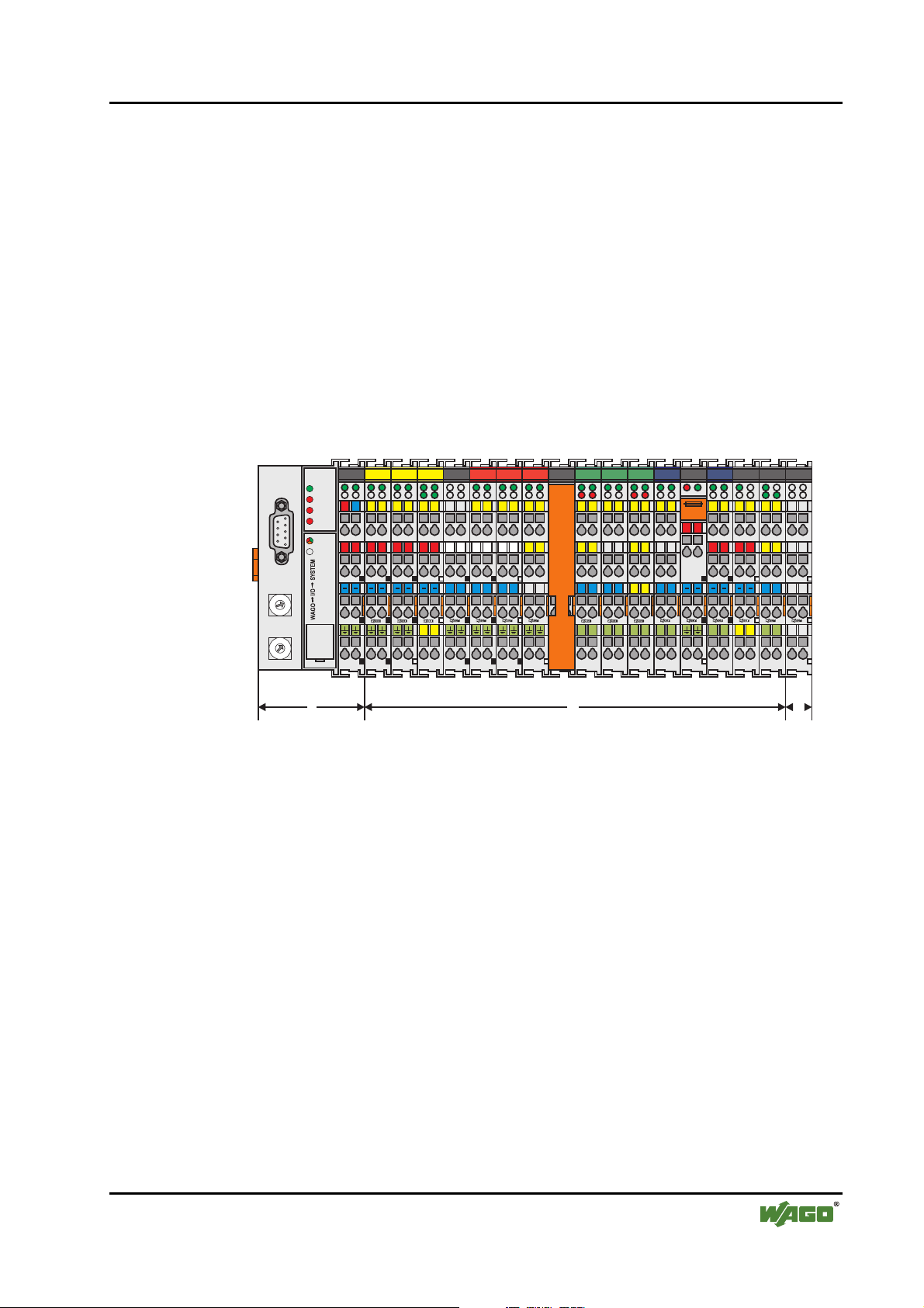
The WAGO-I/O-SYSTEM 750 consists of various components which are capable of providing modular and application specific fieldbus nodes for various
fieldbusses.
A fieldbus node (short: Node) consists in principle of a fieldbus coupler (short:
Coupler) ) or Programmable Fieldbus Controller (short: Controller) ) (1) at the
front end, a number of special I/O modules (2) and a End Module (3) which is
placed at the other end.
PROFIBUS
RUN
BF
24V
01 02 04 050607
0V
DIA
BUS
I/O
03
++++++++
WAGO-I/O-SYSTEM 750 • 5
System Description
TxD RxD
+ +
D+ D-
+ +
RTS CTS
11 12
09 10
L
L
L
13 23
LL L
17
21 22
26
29
30 31 32
max. 6,3A
250 V
+ +
24
181920
161514
27
CL-CL+
750-630 750-650
MM
SS
3
N
N
0
9
8
7
6
X10
0
9
8
7
6
X1
1
5
1
5
2
3
4
750-333
2
3
4
750-400 750-410 750-403 750-454 750-467 750-461
N
08
750-512 750-512 750-513 750-610
750-612
1 2
NN N
M M
S S
M M
25
28
S S
S SMMSS
S S
750-552750-550 750-600
Fig. 2-1: Setting up a fieldbus node for PROFIBUS g01x101x
WAGO-I/O-SYSTEM 750 D R A F T
PROFIBUS 2001-02-27
Page 10

6 • WAGO-I/O-SYSTEM 750
System Description
2.1.2 Coupler/Controller (1)
The Coupler/Controller forms the link between the fieldbus and the field devices with their I/O functions. All control functions required for the faultless
operation of the I/O functions are carried out by the Coupler/Controller. The
connection to different fieldbus systems is established by each of the corresponding Coupler/Controller, e.g. for PROFIBUS, INTERBUS, CAN,
MODBUS etc. In this way a change of the fieldbus system is possible.
The programmable fieldbus controller 750-833 combines the PROFIBUS DP
functionality of the fieldbus coupler 750-333 with the functionality of a Programmable Logic Control (PLC). Programming of the application is done with
WAGO-I/O-PRO in accordance with IEC 61131-3, covering all 5 programming languages. The programmer can access all fieldbus and I/O data.
Characteristics and use of the Controllers:
• The use of decentralized control can better support a PLC or PC
• Signal pre-processing reduces fieldbus transmissions
• Complex applications can be divided into multiple tasks
• Tasks can be prioritized
• Peripheral equipment can be controlled directly, resulting in faster system
response times
• Programmable response in the event of a fieldbus failure
• Simple, self-sufficient control
D R A F T WAGO-I/O-SYSTEM 750
2001-02-27 PROFIBUS
Page 11

2.1.3 I/O Modules (2)
In the I/O modules, the incoming process data is converted. Corresponding to
the different requirements, special I/O modules are available for a variety of
functions. There are digital and analog inputs and outputs and modules for
special functions (Counter modules, Terminal blocks for encoder and resolvers
and communication modules).
2.1.4 End Module (3)
A End Module is needed for faultless operation of the node. The termination
module is always placed as the last module in order to obtain a termination of
the fieldbus node. This module has no I/O function.
WAGO-I/O-SYSTEM 750 • 7
System Description
WAGO-I/O-SYSTEM 750 D R A F T
PROFIBUS 2001-02-27
Page 12
8 • WAGO-I/O-SYSTEM 750
Installation
2.2 Installation
2.2.1 Safty notes
ESD (Electrostatic Discharge)
The modules are equipped with electronic components which may be destroyed by electrostatic discharge.When handling the modules, ensure that the
environment (persons, workplace and packing) is well grounded. Avoid
touching conductive components, e.g. gold contacts.
Attention
Switch off the system prior to working on bus modules!
2.2.2 Mechanical Installation
All system components can be snapped directly on a carrier rail in accordance
with the European standard EN 50022 (DIN 35).
Attention
Ensure that the carrier rail is fastened with countersunk head screws or blind
rivets as the snap-on foot of the I/O components extends onto the carrier rail.
The installation is simple and space saving. All modules have the same shape
to minimize the project commitment.
The reliable positioning and connection of the coupler and the individual I/O
modules is made using a tongue and groove system. Due to the automatic
locking, the individual components are securely seated on the rail after installing.
D R A F T WAGO-I/O-SYSTEM 750
2001-02-27 PROFIBUS
Page 13
WAGO-I/O-SYSTEM 750 • 9
Installation
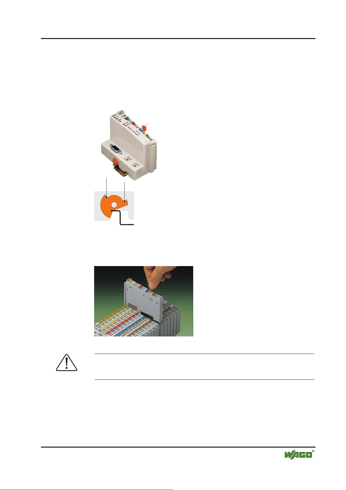
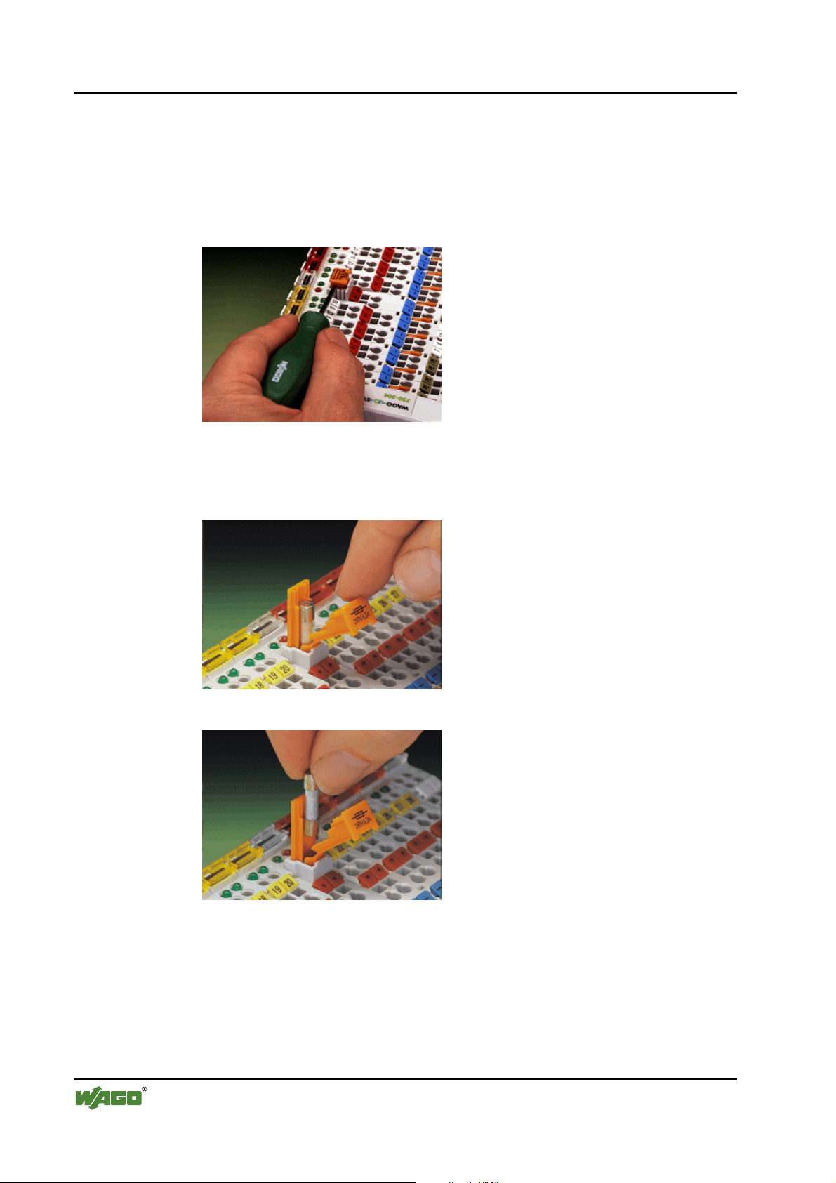
To secure the coupler/controller against moving sideways, fix it with the orange colored locking disc on the carrier rail. To fix, insert a screwdriver into
the top groove of the locking disc and press.
To pull out the fieldbus coupler, release the locking disc by pressing on the
bottom groove with a screwdriver and then pulling the orange colored unlocking lug.
Entriegelungs-
lasche
fixieren
Fig. 2-2: Coupler/Controller and unlocking lug g012201d
lösen
It is also possible to release an individual I/O module from the unit by pulling
an unlocking lug.
Fig. 2-3: Releasing a I/O Module p0xxx01x
Danger
Ensure that an interruption of the PE will not result in a condition which
could endanger a person or equipment!
WAGO-I/O-SYSTEM 750 D R A F T
PROFIBUS 2001-02-27
Page 14
10 • WAGO-I/O-SYSTEM 750
Installation
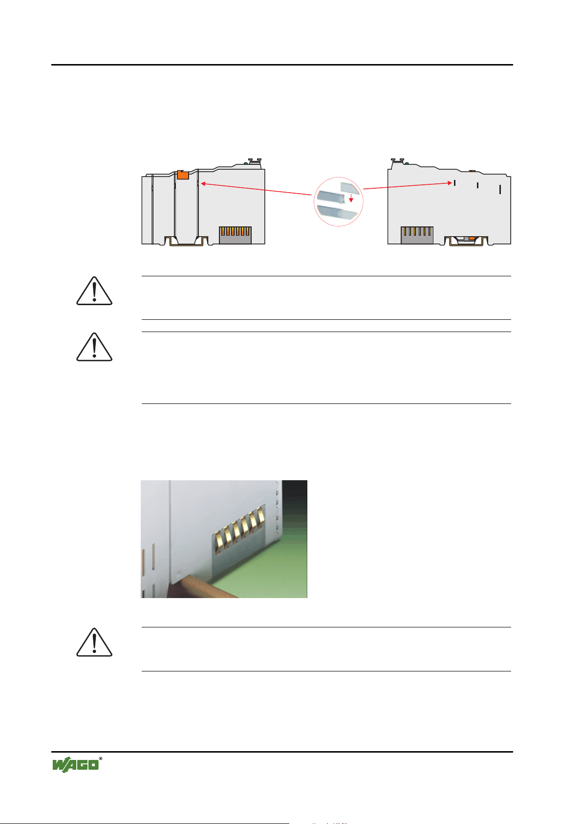
Self-cleaning power jumper contacts conduct the supply voltage for the field
side. They are located on either side of the modules. The female contacts on
the right-hand side of the fieldbus coupler and the bus modules are designed as
spring contacts to protect against accidental contact. Male contacts are located
on the left-hand side of the bus modules.
Fig. 2-4: Power Jumper Contacts g01xx00d
Danger
The power contacts are sharp-edged. Handle the module carefully to prevent
injury.
Pos. 1
Pos. 2
Attention
Please take into consideration that some bus modules have no or only some
power jumper contacts. The design of some modules does not physically allow assembly them in rows as the grooves for the male contacts are closed at
the top.
The data contacts are designed as self-cleaning gold spring contacts which
automatically produce a secure connection.
Fig. 2-5: Data contacts p0xxx07x
Warning
Do not connect the I/O module to gold spring contacts in order to avoid soiling or scratches!
D R A F T WAGO-I/O-SYSTEM 750
2001-02-27 PROFIBUS
Page 15
2.3 Electrical Installation
2.3.1 Wire Connection
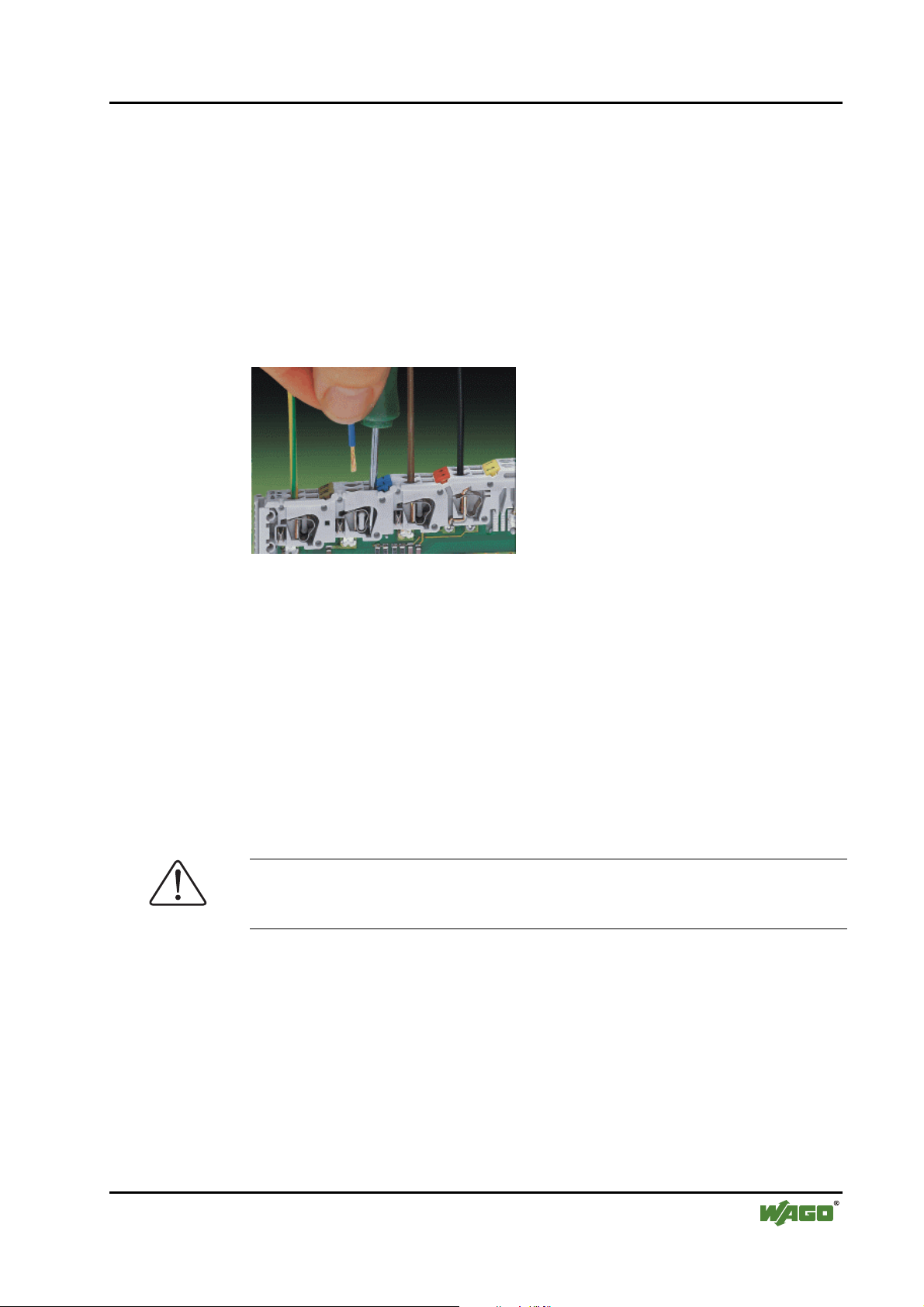
Conductors with a cross section of 0.08 to 2.5 mm² (AWG 28-12) can be connected using a CAGE CLAMP connection to achieve a vibration resistant,
fast and maintenance free connection. To actuate CAGE CLAMP enter an
actuation tool in the opening above the connection. Following this, enter the
conductor in the corresponding opening. The conductor is clamped securely
with the removal of the actuation tool.
WAGO-I/O-SYSTEM 750 • 11
Electrical Installation
Fig. 2-6: Inserting conductor end p0xxx06x
The clamping force adjusts automatically to the cross section. The full surface
of the CAGE CLAMP pressure is applied against the conductor without
damaging it. Conductor deformation is compensated for and self-loosening is
avoided. The transition point between the conductor and the CAGE CLAMP
is protected against corrosive influences. The connection can be made quickly
and is also maintenance free, saving the costs for a periodic checking of terminal connections.
Two carrier rail contacts responsible for the electrical contact between the
grounded carrier rail and the controller, are fitted underneath the coupler/controller.
Attention
Ensure a perfect contact point between carrier rail contacts and carrier rail.
The carrier rail must be grounded.
WAGO-I/O-SYSTEM 750 D R A F T
PROFIBUS 2001-02-27
Page 16
12 • WAGO-I/O-SYSTEM 750
Electrical Installation
2.3.2 Change fuse
Some Power supply modules of the WAGO-I/O-SYSTEM 750 are equipped
with a fuse holder. To isolate the modules to the right of the power supply, the
fuse can be removed from the fuse holder. For this insert a srew driver into one
of the slits available on each side and lift the holder
Fig. 2-7: Removing the fuse holder p0xxx05x
The fuses can be removed from or inserted into the holder with the fuse holder
cover and push the fuse holder pushed back into the original position.
Fig. 2-8: Opening the fuse holder p0xxx03x
Fig. 2-9: Change fuse p0xxx04x
D R A F T WAGO-I/O-SYSTEM 750
2001-02-27 PROFIBUS
Page 17
2.4 Power supply
WAGO-I/O-SYSTEM 750 • 13
Power supply
1
2
750-512 750-512 750-513 750-610 750-552750-550 750-600750-616
750-612
~
24V 24V 24V
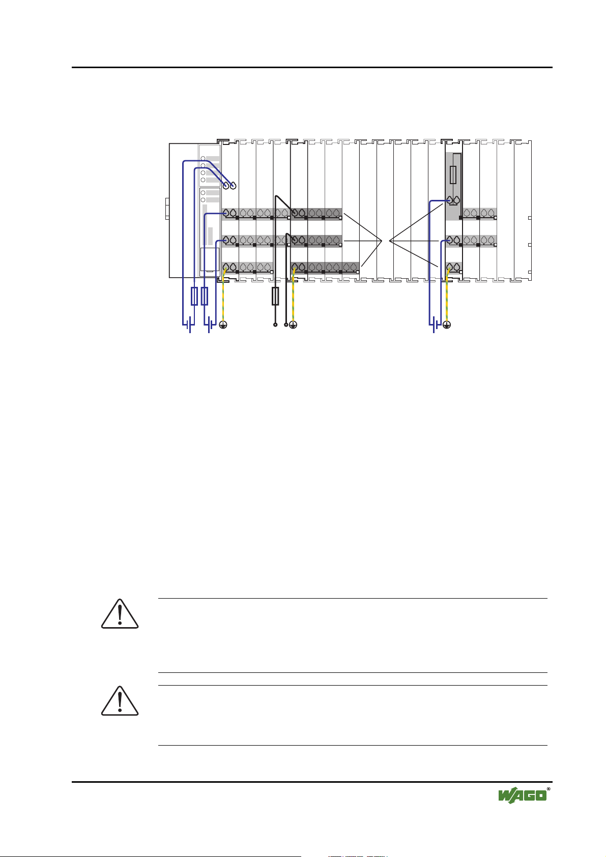
Fig. 2-10: Power supply g01xx02x
230V
750-630 750-650750-400 750-410 750-403 750-454 750-467 750-461
1 – Power supply System
2 – Power supply Field-side
The power supply on the field side is electrically isolated from the system supply. In this manner sensors and actuators can be supplied and fused by a separate voltage source.
If a non-regulated power supply is used for the coupler/controller electronics
24 V voltage supply , it must be filtered through a capacitor (200 µF per 1 A
load current). To this effect a back-up capacitor module (Order-No. 288-824)
was developed for the WAGO-I/O-SYSTEM. This module serves to regulate a
noisy 24 V DC voltage supply, to keep the ripple voltage within specified limits. The cause for these fluctuations could be a voltage interruption on the primary side, a secondary side overload or the switching of ”non quenched“ inductance or capacitance.
Warning
The supply modules + and – which are permanently integrated on the buscouplers, can be supplied with 24 V DC only.
120 V AC and 230 V AC can only be supplied via modules 750-609, 750-611
and 750-612!
Warning
The ground (earth) field side contact should be disconnected when testing the
isolation. Otherwise the results could be wrong or the module could be destroyed.
WAGO-I/O-SYSTEM 750 D R A F T
PROFIBUS 2001-02-27
Page 18

14 • WAGO-I/O-SYSTEM 750
Power supply
2.4.1 System supply voltage
The system supply voltage (24 V DC) is filtered with a voltage regulator before powering the coupler electronics as well as to the internal bus. Electrical
isolation from the external fieldbus system depends on the type of Coupler/Controller.
The internal bus includes the internal communication between the coupler/controller and the bus modules as well as the power supply for the bus
modules. The power supply is limited to a maximum value. This value depends on the type of Coupler/Controller. If the sum of the internal power consumption of all bus modules exceeds this value, it is necessary to add additional internal system supply modules (Order-No. 750-613).
The control electronics in the bus modules are powered by snap-fit mounting
the bus modules using the internal bus contacts. A reliable contact is assured
by the gold plated, self cleaning slide contacts. The removal of a bus module
will cause an interruption in communication to the following bus modules.
The coupler/controller identifies the interruption point and displays a corresponding fault message.
Warning
Removing or inserting the I/O modules with the voltage applied can lead to
undefined conditions. For this reason only undertake work on the I/O modules
when isolated from the power supply!
D R A F T WAGO-I/O-SYSTEM 750
2001-02-27 PROFIBUS
Page 19
2.4.2 Supply Voltage Field Side
The voltage is automatically supplied when the I/O modules are snapped together. Self-cleaning power jumper contacts (P.J.C.s) ensure safe connections.
The current capacity of the power contacts is 10 A max.
The PE contact is a preceding ground (earth) contact corresponding to the
standards which can be used as a protective earth. The contact has a leakage
capacity of 125 A.
Warning
Produce a low impedance connection from the carrier rail to the PE contact
point in the switch cabinet.
Attention
Depending on the I/O function, some modules do not have P.J.C.s. It is important to note this when assembling a node. Many modules require field side
power, many do not. Please review the circuit diagrams of the individual modules. An additional power supply module may be necessary.
Refer to the individual terminal/module data sheets!
WAGO-I/O-SYSTEM 750 • 15
Power supply
When adding a power supply module, the field supply is always interrupted at
the power contacts. From this point a new power supply is made, which can
also include a potential change. This feature guarantees a high degree of system flexibility.
WAGO-I/O-SYSTEM 750 D R A F T
PROFIBUS 2001-02-27
Page 20
16 • WAGO-I/O-SYSTEM 750
Manufacturing Number
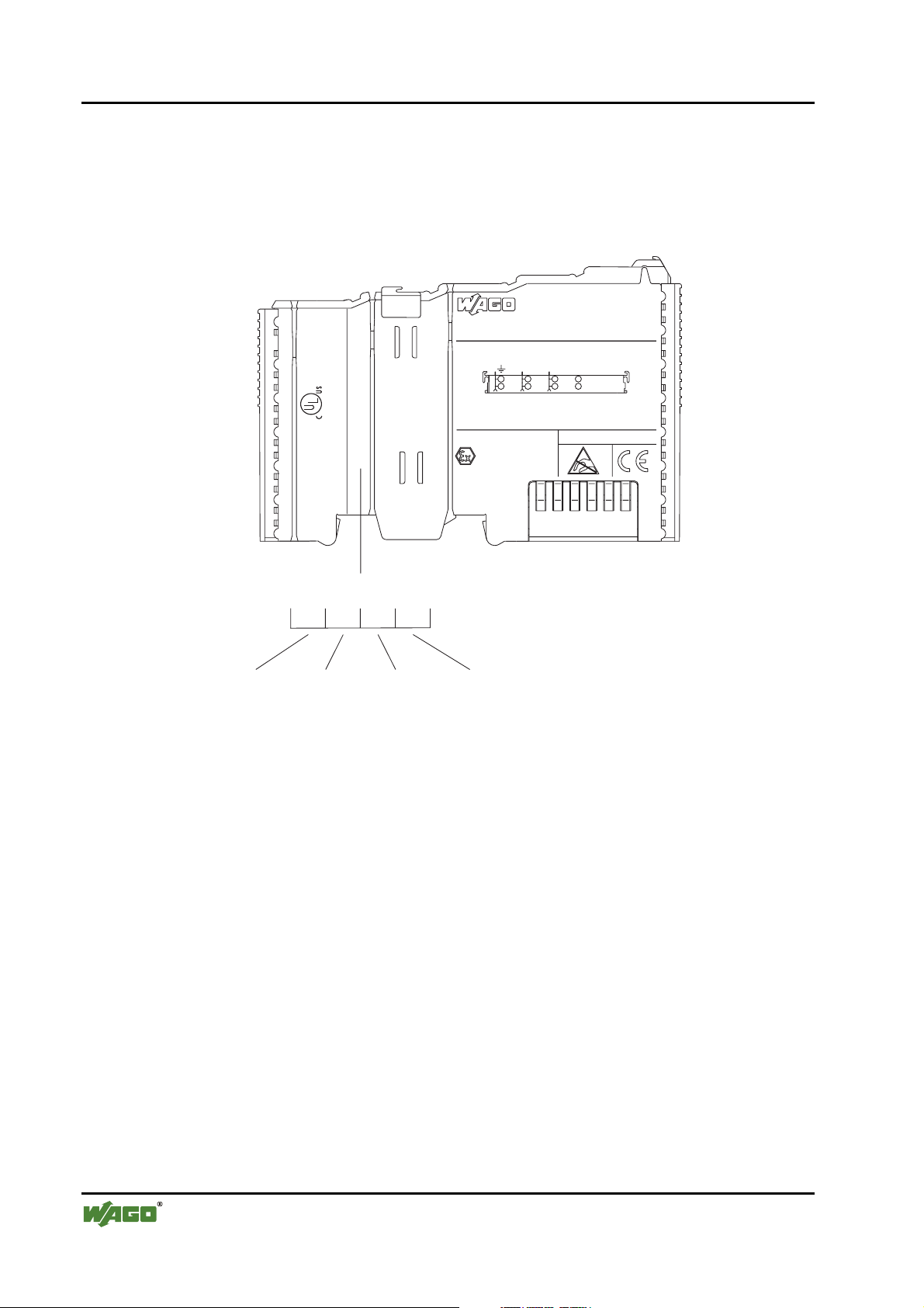
2.5 Manufacturing Number
The production number is part of the lateral marking on the component. The
number contains the production date, the software version and the hardware of
the component.
Hansastr. 27
D-32423 Minden
ITEM-NO.:750-400
2DI 24V DC 3.0ms
2
0.08-2.5mm
24V DC
CL I DIV
AWG 28-14
Grp. A B C D
55°C max ambient
24246
LISTED 22ZA AND 22XM
0901--02----03
op temp code T4A
0V 24V DI1
II3G
KEMA 01ATEX1024 X
EEx nA II T4
Di2
PATENTS PENDING
Manufacturing Number
0
9
Calendar
week
1
0
-
Year Software
version
2
0
0
-
Hardware
version
Fig. 2-11: Manufacturing Number g01xx09e
The remaining digits and characters represent internal information by
WAGO Kontakttechnik GmbH.
As of calendar week 09/2001, the production number is additionally printed on
the cover of the configuration and programming interface of the fieldbus coupler or controller.
D R A F T WAGO-I/O-SYSTEM 750
2001-02-27 PROFIBUS
Page 21
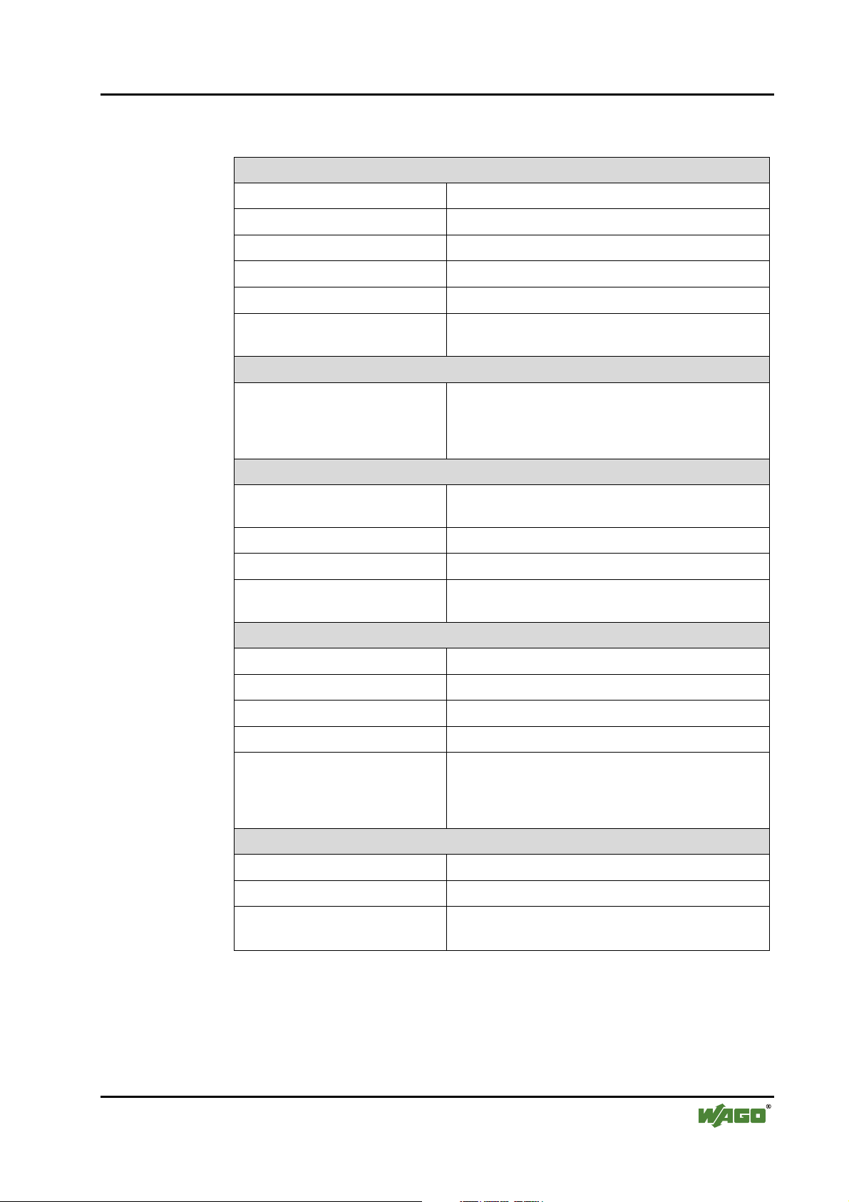
2.6 Technical Data
Mechanic
Material Polycarbonat, Polyamid 6.6
Installation on DIN 35 with interlock
modular by double featherkey-dovetail
Mounting position any position
WAGO-I/O-SYSTEM 750 • 17
Technical Data
Length of entire node
≤ 831 mm
Marking marking label type 247 and 248
paper marking label 8 x 47 mm
Wire range
Wire range CAGE CLAMP® Connection
0,08 mm² ... 2,5 mm²
AWG 28-14
8 – 9 mm Stripped lenght
Contacts
Power jumpers contacts blade/spring contact
self-cleaning
Current via power contacts
Voltage drop at I
max
max
10 A
< 1 V/64 modules
Data contacts slide contact, hard gold plated
1,5µ, self-cleaning
Climatic environmental conditions
Operating temperature 0 °C ... 55 °C
Storage temperature -20 °C ... +85 °C
Relative humidity 95 % without condensation
Resistance to harmful substances acc. to IEC 60068-2-42 and IEC 60068-2-43
Special conditions Ensure that additional measures for components are
taken, which are used in an environment involving:
– dust, caustic vapors or gasses
– ionisating radiation.
Mechanical strenght
Vibration resistance acc. to IEC 60068-2-6
Shock resistance acc. to IEC 60068-2-27
Free fall acc. to IEC 60068-2-32
≤ 1m (module in original packing)
WAGO-I/O-SYSTEM 750 D R A F T
PROFIBUS 2001-02-27
Page 22
18 • WAGO-I/O-SYSTEM 750
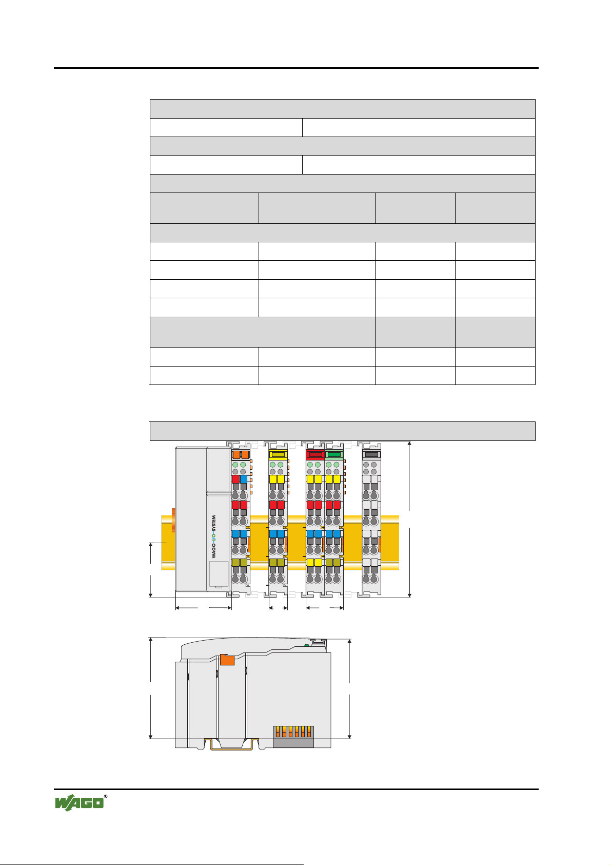
Technical Data
Safe electrical isolation
Air and creepage distance acc. to IEC 60646-1
Degree of protection
Degree of protection IP 20
Electromagnetic compatibility*
Derective Test values Strenght
class
Evaluation
criteria
Immunity to interference acc. to EN 50082-2 (95)
EN 61000-4-2 4kV/8kV (2/4) B
EN 61000-4-3 10V/m 80% AM (3) A
EN 61000-4-4 2kV (3/4) B
EN 61000-4-6 10V/m 80% AM (3) A
Emmission to interference acc. to
EN 50081-2 (94)
Measuring
distance
Class
EN 55011 30 dBµV/m (30m) A
37 dBµV/m
* Exception: 750-630, 750-631
Dimensions
02
01
A
B
24V 0V
A
C
B
D
A
C
D
A
C
B
B
D
A
C
D
C
B
D
+
+
100
-
-
PE PE
35
51
65
Seitenansicht Koppler/Controller
12
24
64
Abmessungen in mm
Fig. 2-12: Dimensions g01xx05d
D R A F T WAGO-I/O-SYSTEM 750
2001-02-27 PROFIBUS
Page 23

3 Fieldbus coupler / controller
3.1 Fieldbus coupler 750-333
This chapter includes:
3.1.1 Description......................................................................................21
3.1.2 Hardware.........................................................................................22
3.1.2.1 View .........................................................................................22
3.1.2.2 Device supply...........................................................................23
3.1.2.3 Fieldbus connection..................................................................24
3.1.2.4 Display elements ......................................................................25
3.1.2.5 Station address .........................................................................26
3.1.2.6 Configuration interface ............................................................26
3.1.3 Operating system.............................................................................27
3.1.4 Process image..................................................................................28
3.1.4.1 Local process image .................................................................28
3.1.4.2 Allocation of the input and output data....................................29
3.1.5 Configuration ..................................................................................30
3.1.5.1 GSD files..................................................................................31
3.1.5.2 Identification bytes...................................................................32
3.1.5.3 Example....................................................................................34
3.1.6 Parameterising the coupler..............................................................36
3.1.7 Configuring the process data channel .............................................38
3.1.8 Configuration and parameterisation of I/O modules.......................39
3.1.8.1 Digital I/O modules..................................................................39
3.1.8.1.1 2 DI I/O modules......................................................................39
3.1.8.1.2 4 DI I/O modules......................................................................40
3.1.8.1.3 2 DI I/O modules modules with 1 bit diagn. per channel.........41
3.1.8.1.4 2 DO I/O modules ....................................................................42
3.1.8.1.5 2 DO I/O modules with 1 bit diagn. per channel......................43
3.1.8.1.6 2 DO I/O module with 2 bit diagn. per channel .......................44
3.1.8.1.7 4 DO I/O modules ....................................................................45
3.1.8.1.8 2 DI/DO I/O module with 1 bit diagn. per channel..................46
3.1.8.1.9 Internal system supply module with diagnosis.........................47
3.1.8.2 Analog I/O modules .................................................................48
3.1.8.2.1 2 AI I/O modules......................................................................48
3.1.8.2.2 4 AI I/O module .......................................................................49
3.1.8.2.3 2 AO I/O modules ....................................................................50
3.1.8.3 Digital special modules ............................................................51
3.1.8.3.1 Counter modules ......................................................................51
3.1.8.3.2 PWM module ...........................................................................52
3.1.8.4 Distance and Angle Messurment Modules...............................53
3.1.8.4.1 SSI encoder interface................................................................53
3.1.8.4.2 Incremental encoder interface ..................................................54
3.1.8.4.3 Digital impulse interface ..........................................................55
3.1.8.5 Serial interfaces ........................................................................56
3.1.9 Diagnosis.........................................................................................57
Fieldbus coupler / controller • 19
Fieldbus coupler 750-333
WAGO-I/O-SYSTEM 750 D R A F T
PROFIBUS 2001-02-27
Page 24

20 • Fieldbus coupler / controller
Fieldbus coupler 750-333
3.1.9.1 Station status 1 to 3 ..................................................................58
3.1.9.2 PROFIBUS-DP master address................................................58
3.1.9.3 Manufacturer‘s identification...................................................58
3.1.9.4 Identification based diagnosis ..................................................58
3.1.9.5 Device status ............................................................................59
3.1.9.5.1 Internal status messages and arguments...................................60
3.1.9.5.2 Internal bus status messages and arguments ............................60
3.1.9.5.3 PROFIBUS-DP status messages and arguments......................61
3.1.9.6 Channel based diagnosis ..........................................................62
3.1.9.6.1 Fault types of I/O modules with diagnostic capability.............63
3.1.9.6.2 I/O modules fault cases ............................................................64
3.1.10 LED signalling ................................................................................65
3.1.10.1 Blink code ................................................................................65
3.1.10.2 Fieldbus status..........................................................................66
3.1.10.3 Fault message via blink code of the BUS-LED........................67
3.1.10.4 Node status ...............................................................................68
3.1.10.5 Fault message via the blink code of the I/O LED.....................69
3.1.10.6 Supply voltage status................................................................70
3.1.11 Fault behaviour ...............................................................................71
3.1.11.1 Fieldbus failure.........................................................................71
3.1.11.2 Internal bus fault.......................................................................72
3.1.12 Technical data .................................................................................73
D R A F T WAGO-I/O-SYSTEM 750
2001-02-27 PROFIBUS
Page 25

3.1.1 Description
The fieldbus coupler 750-333 displays the peripheral data of all I/O modules in
the WAGO-I/O-SYSTEM 750 on PROFIBUS DP.
In the initialisation phase the bus coupler determines the physical structure of
the node and creates a process image from this with all inputs and outputs. I/O
modules with a bit width smaller than 8 can be combined to form one byte in
order to optimise the address space.
In addition the possibility exists to deactivate projected I/O modules. In this
manner the physical structure of the node can be individually designed with
regard to the peripheral signals, without undertaking any changes to an already
existing control application.
The diagnosis concept is based on an identification and channel based diagnosis in accordance with EN 50170. Thus it is not necessary to program modules
for the evaluation of manufacturer specific diagnosis information.
Fieldbus coupler / controller • 21
Fieldbus coupler 750-333
• Max. process data length 128 Byte (input and output process image)
• Automatic recognition of transmission speed on the PROFIBUS from
9.6 kBd to 12 MBd
• All I/O modules from the WAGO-I/O-SYSTEM 750 are supported
• Configuration modules can be parameterised as wildcards.
• Parameterable substitute value for each channel
• D-Sub 9 pole bus connection
WAGO-I/O-SYSTEM 750 D R A F T
PROFIBUS 2001-02-27
Page 26
22 • Fieldbus coupler / controller
Fieldbus coupler 750-333
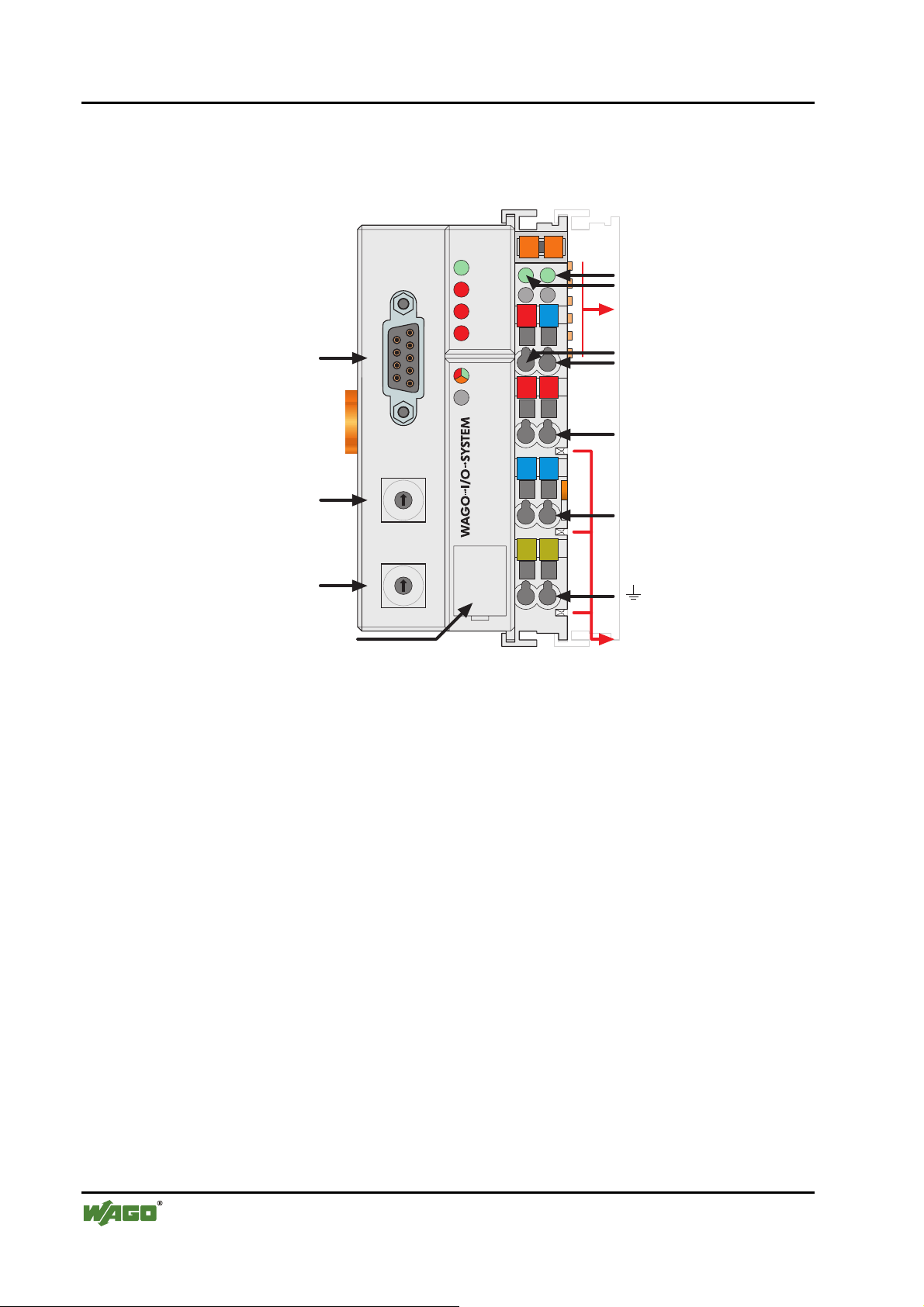
3.1.2 Hardware
3.1.2.1 View
Status der
Feldbusanschluss
D-Sub
PROFIBUS
RUN
BF
DIA
BUS
I/O
01 02
A
B
0V
24V
++
Betriebsspannung
C
D
-Leistungskontakte
-System
Datenkontakte
Versorgung
24V
0V
Versorgung über
Leistungskontakte
24V
ADDRESS
--
0V
Adresse
x1
1
0
9
2
3
8
4
7
6
5
750-333
PE PE
Leistungskontakte
Adresse
KonfigurationsSchnittstelle
9
8
7
x10
1
0
6
5
2
3
4
Fig. 3-1: Fieldbus coupler 750-333 PROFIBUS DP/V1 g033300d
The fieldbus coupler comprises of:
• Supply module with Internal system supply module for the system supply
as well as power jumper contacts for the field supply via I/O module assemblies.
• Fieldbus interface with the bus connection
• 2 rotary switches for the station address (decimal)
• Display elements (LED's) for status display of the operation, the bus com-
munication, the operating voltages as well as for fault messages and diagnosis
• Electronics for communication with the I/O modules (internal bus) and the
fieldbus interface
D R A F T WAGO-I/O-SYSTEM 750
2001-02-27 PROFIBUS
Page 27
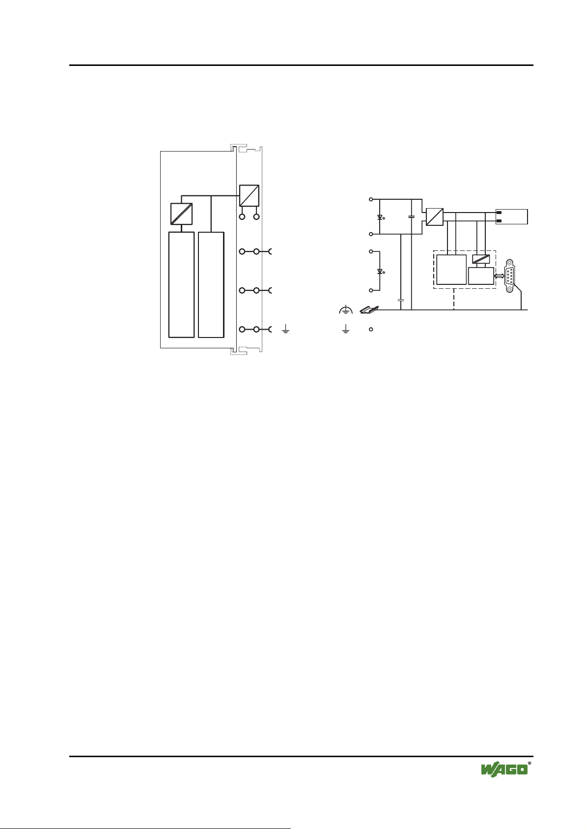
3.1.2.2 Device supply
The supply is made via terminal bocks with CAGE CLAMP® connection. The
device supply is intended both for the system and the field units.
Fieldbus coupler / controller • 23
Fieldbus coupler 750-333
1
5
24V/0V
10nF
DC
DC
Bus-
klemmen
0V
24V
2
6
24V
3
4
750-333
7
0V
8
NTERFACE
FELDBUS I
ELEKTRONIK
24V
0V
10nF
ELEKTRONIK
FELDBUS
INTERFACE
Fig. 3-2: Device supply g012105d
The integrated internal system supply module generates the necessary voltage
to supply the electronics and the connected I/O modules.
The fieldbus interface is supplied with electrically isolated voltage from the
internal system supply module.
WAGO-I/O-SYSTEM 750 D R A F T
PROFIBUS 2001-02-27
Page 28
24 • Fieldbus coupler / controller
Fieldbus coupler 750-333
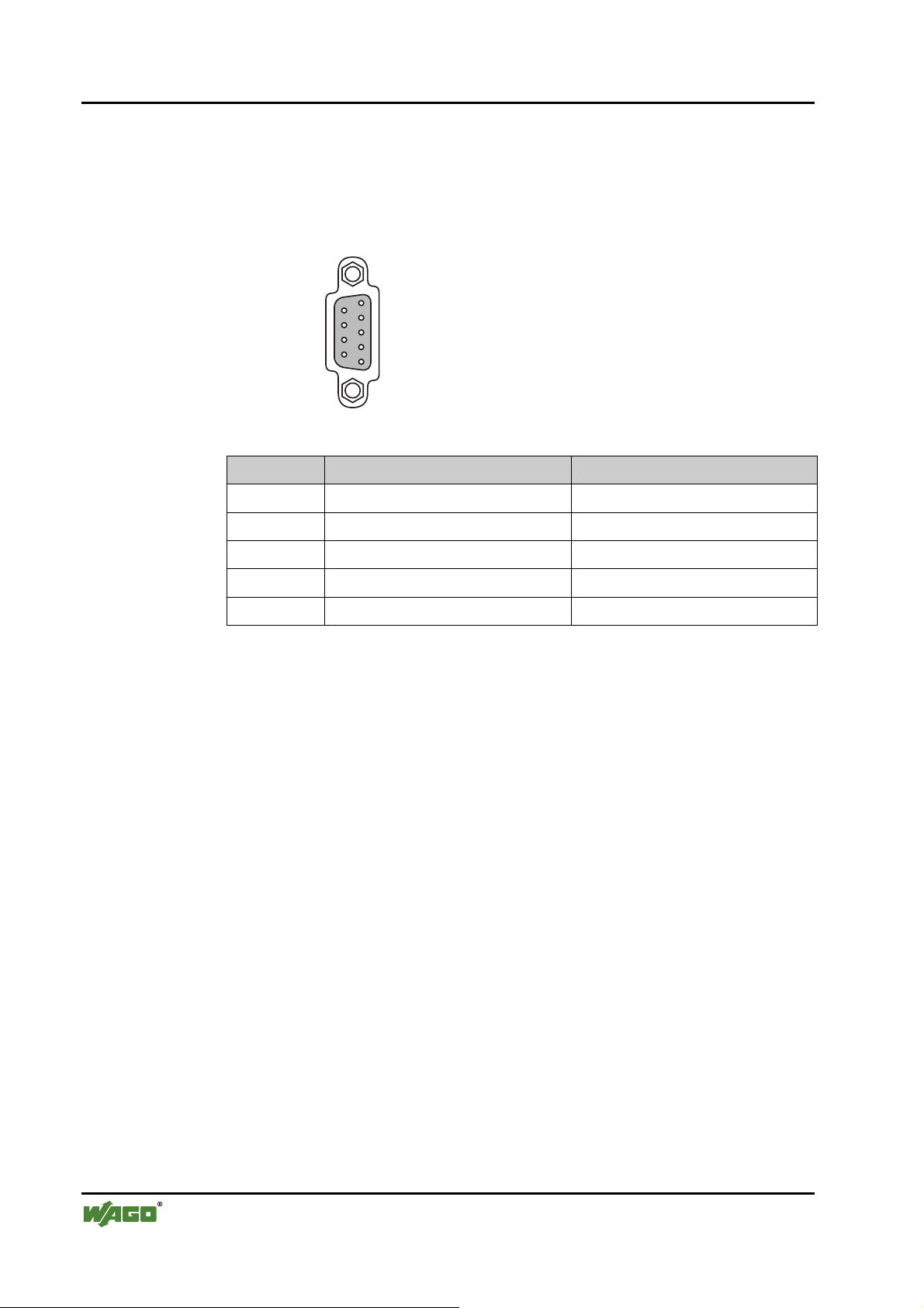
3.1.2.3 Fieldbus connection
The PROFIBUS interface is designed as a Sub-D connection in accordance
with the US Standard EIA RS 485 for cable linked data transmission.
9-pol. D-Sub-Buchse
9
VP
8
7
6
RxD/TxD-N
Fig. 3-3: Bus connection, D-SUB g012102d
Pin Signal Description
3 RxD(TxD)-P Transmit (receive) signal
5
DGND
4
RTS
3
RxD/TxD-P
2
1
4 RTS Ready To Send
5 GND Supply ground (earth)
6 Vcc Voltage supply
8 RxD(TxD) N Transmit (receive) signal
The electrical isolation between the fieldbus system and the electronics is
achieved by means of DC/DC converters and optocouplers in the fieldbus interface.
The connection point is mechanically lowered permitting fitting in an 80 mm
high switch box once connected.
D R A F T WAGO-I/O-SYSTEM 750
2001-02-27 PROFIBUS
Page 29
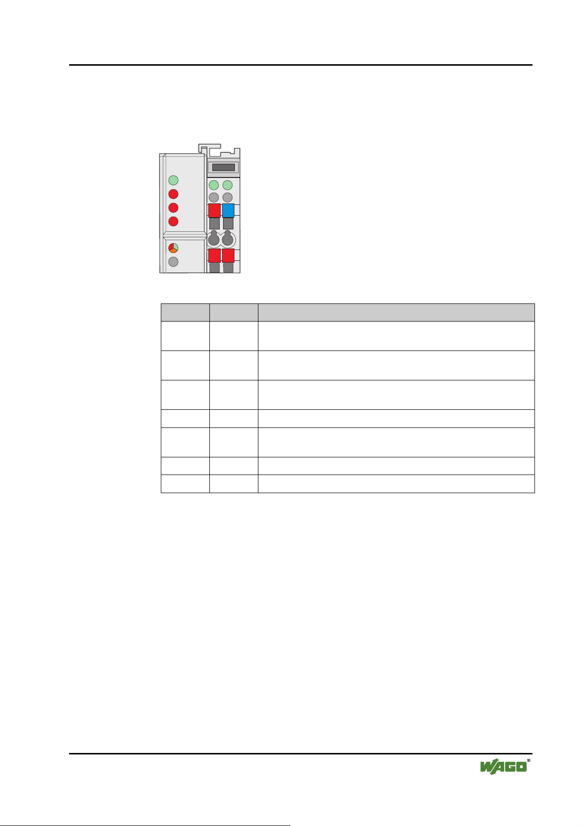
3.1.2.4 Display elements
The operating condition of the fieldbus coupler or node is signalled via light
diodes (LED).
PROFIBUS
A
RUN
B
BF
DIA
BUS
24V
0V
Fieldbus coupler / controller • 25
Fieldbus coupler 750-333
C
D
I/O
++
Fig. 3-4: Display elements 750-333 g012106x
LED Colour Meaning
RUN green The 'RUN' LED indicates to the operator if the fieldbus coupler /
controller is correctly initialised.
BF red The 'BF'-LED indicates whether the communication functions via
the PROFIBUS.
DIA red The 'DIA' LED indicates an external diagnosis. The signalling is not
supported by all devices.
BUS red The 'BUS'-LED signals a projecting fault.
IO red /green
/ orange
The 'I/O'-LED indicates the operation of the node and signals faults
encountered.
A green Status of the operating voltage system
C green Status of the operating voltage – power jumper contacts
WAGO-I/O-SYSTEM 750 D R A F T
PROFIBUS 2001-02-27
Page 30
26 • Fieldbus coupler / controller
Fieldbus coupler 750-333
3.1.2.5 Station address
The station address (decimal) is determined using two rotary switches on the
electronic module.
ADDRESS
x1
1
0
9
2
3
8
4
7
6
5
x10
1
0
9
2
3
8
4
7
6
5
Fig. 3-5: Setting the station address g012102d
The switch „x1“ determines the units position of the address. The switch
„x10“ determines the tens positions of the address. Valid station addresses are
between 1 and 99. The coupler also permits the station address 0.
The station address is taken over by the fieldbus coupler after switching on the
device (initialisation phase). Adjustments of the switch have no effect during
operation.
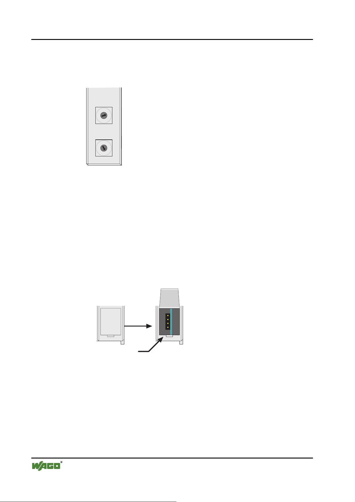
3.1.2.6 Configuration interface
The configuration interface used for the communication with WAGO-I/OCHECK or for firmware upload is located behind the cover flap.
Klappe
öffnen
KonfigurationsSchnittstelle
Fig. 3-6: Configuration interface g01xx06d
The communication cable (750-920) is connected to the 4 pole header.
D R A F T WAGO-I/O-SYSTEM 750
2001-02-27 PROFIBUS
Page 31
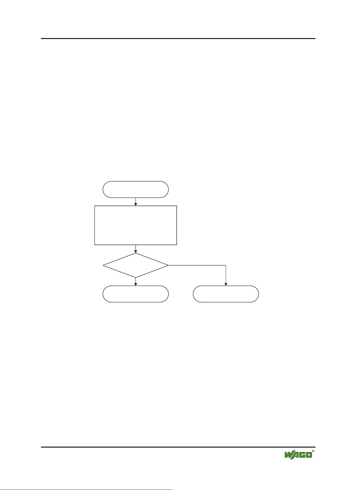
3.1.3 Operating system
Following the configuration of the master activation and the electrical installation if the fieldbus station can start up the system.
After switching on the supply voltage the coupler performs a self test of all
functions of its devices, the I/O module and the fieldbus interface. Following
this the I/O modules and the present configuration is determined, whereby an
external not visible list is generated. This list includes an input and an output
area on which is represented the fieldbus RAM of the protocol chip.
In the event of a fault the coupler changes to the "Stop" condition. The "I/O"
LED flashes red. After a fault free start up the coupler changes to the "Fieldbus
start" status and the "I/O" LED lights up green.
Versorgungsspannung
einschalten
Fieldbus coupler / controller • 27
Fieldbus coupler 750-333
Koppler-Selbsttest,
Ermittlung Busklemmen
und Konfiguration,
Erstellung interner Liste
“I/O”-LED blinkt rot
Fehler
Nein
Feldbusstart
“I/O”-LED leuchtet grün
Fig. 3-7: Operating system 750-333 g012113d
Ja
Stop
“I/O”-LED blinkt rot
WAGO-I/O-SYSTEM 750 D R A F T
PROFIBUS 2001-02-27
Page 32

28 • Fieldbus coupler / controller
Fieldbus coupler 750-333
3.1.4 Process image
3.1.4.1 Local process image
After switching on, the coupler recognises all I/O modules plugged into the
node which supply or wait for data (data width/bit width > 0). In nodes analog
and digital I/O modules can be mixed.
Note
For the number of input and output bits or bytes of the individually activated
on I/O modules please refer to the corresponding I/O module description.
The coupler produces an internal process image from the data width and the
type of type of I/O module as well as the position of the I/O modules in the
node. It is divided into an input and an output data area.
The data of the digital I/O modules is bit orientated, i.e. the data exchange is
made bit for bit. The analog I/O modules are representative for all byte orientated I/O modules, i.e. those where the data exchange is made byte for byte.
These I/O modules include for example the counter modules, I/O modules for
angle and path measurement as well as the communication modules.
The data of the I/O modules is separated for the local input and output process
image in the sequence of their position after the coupler in the individual process image.
Note
A process image restructuring may result if a node is changed or extended. In
this case the process data addresses also change in comparison with earlier
ones.
D R A F T WAGO-I/O-SYSTEM 750
2001-02-27 PROFIBUS
Page 33

3.1.4.2 Allocation of the input and output data
The process data is exchanged via the PROFIBUS with the higher ranking
controls (master). A maximum of 128 bytes of data is transmitted from the
master to the coupler or from the node to the output data. The coupler responds by returning a maximum of 128 bytes input data to the master.
Modules are configured when projecting the node which can be taken over
from a hardware catalogue of the configuration programs. The information
covering the possible modules is contained in the GSD files.
The coupler generates an internal mapping in accordance with the installed and
configured settings of the node, in which the allocation of the input and output
data is determined in the local process image with the position in the
PROFIBUS DP Telegram.
Master, z. B. SPS
CPU
Fieldbus coupler / controller • 29
Fieldbus coupler 750-333
750-
1234 5 6789
DI
AI
AI
DOAOAO
DO
Anschaltung
452
504 504
550 550
600
Master-
Adressen
I
O
I
O
byteweise Zuordnung,
Erstellung aufdem PC
I
O
PROFIBUS
PROFIBUS
402DI402 452
ZuordnungslisteZuordnungsliste
II
OO
bit- und byteweise
Zuordnung,
Erstellung automatisch
durch den Koppler
Fig. 3-8: Allocation of the input and output data g012117d
WAGO-I/O-SYSTEM 750 D R A F T
PROFIBUS 2001-02-27
Page 34

30 • Fieldbus coupler / controller
Fieldbus coupler 750-333
3.1.5 Configuration
The configuration of the node is performed in accordance with the physical requirements of the fieldbus coupler and I/O modules.
The fieldbus coupler or the process data channel is to be configured on the first
slot.
The other slots are configured in accordance with the physical requirements of
the I/O modules. Here only I/O modules with process data are relevant. The
supply modules without diagnosis, bus internal system supply module and the
termination module are to be ignored for the configuration because they do not
provide any process data.
One or tow modules are entered in the hardware catalogue for each I/O module. The module appear as 750-xyz ..., for example 750-400 2 DI/24 V DC/3.0
.
ms
For all binary modules an addition is made to the entry *750-xyz .... When us-
ing these denominations the coupler adds the binary information to the current
module in a byte which was previously opened with 750-xyz .... The use of a
„*“ module is only permitted when the number of channels is less than or
equal to the remaining bits in the previously opened byte. The binary I/O modules combined in a byte can be arranged at separate locations, i.e. binary I/O
modules with a different signal type or also byte orientated I/O modules can be
connected between.
In order to be able to individually arrange the scope of connected periphery
units independent of the control program, it is possible to parameterise I/O
modules in the configuration table as „not connected“. In this manner process
data still present is filtered for the individual module and not transferred on the
PROFIBUS DP to and read by the periphery units.
D R A F T WAGO-I/O-SYSTEM 750
2001-02-27 PROFIBUS
Page 35
3.1.5.1 GSD files
Under PROFIBUS DP the features of the modules are defined by the manufacturers in the form of a GSD file (unit basic data).
Structure, content and coding of this unit main data are standardised and made
available to the user allowing to project optional DP slaves using the project
units of various manufacturers.
Further information
i
The PNO provides information about the GSD files of all listed manufacturers.
GSD and symbol files for the configuration of the I/O modules are available
under the order number 750-910 on disks or from the WAGO INTERNET
page.
http://www.wago.com
Fieldbus coupler / controller • 31
Fieldbus coupler 750-333
GSD file for I/O-Module 750-333 WAGOB754.GSD
The GSD file is read by the configuration software and the corresponding settings transmitted. For the necessary inputs and handling steps please refer to
the software user manuals.
WAGO-I/O-SYSTEM 750 D R A F T
PROFIBUS 2001-02-27
Page 36

32 • Fieldbus coupler / controller
Fieldbus coupler 750-333
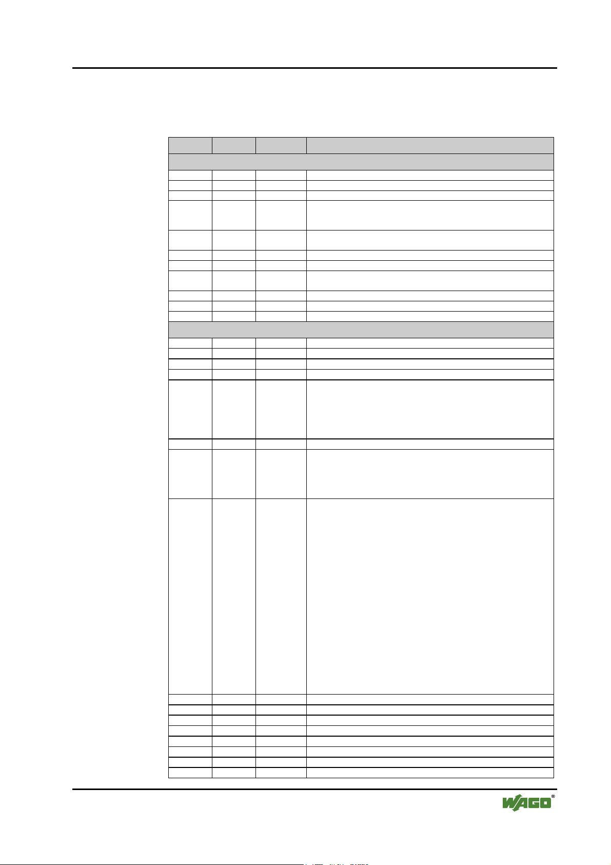
3.1.5.2 Identification bytes
The identification bytes contain information about the design and structure of
the unit inputs and outputs. For projecting each I/O module, or each channel is
allocated an identification (module).
Bit Meaning
7 6 5 4 3 2 1 0
0
0
0
...
1
0
0
1
0
0
1
1
1
Data length
1 byte or word
0
0
0
2 bytes or words
1
0
0
3 bytes or words
0
1
0
...
...
...
...
16 bytes or words
1
1
1
Input and output
spec. identification formats
Input
Output
Input and output
Format
0
1
0 = Byte structure
1 = Word structure
Consistence over
0
1
Byte or word
Total length
This information is saved in the GSD file. During projecting the I/O module is
selected in accordance with the article number using the configuration software in the hardware catalogue.
Module Ident. Module Ident
750-333 No process data channel 0x00 750-333 2 Byte process data channel 0xB1
750-400 2 DI/24 V DC/3.0 ms 0x10 *750-400 2 DI/24 V DC/3.0 ms 0x00
750-401 2 DI/24 V DC/0.2 ms 0x10 *750-401 2 DI/24 V DC/0.2 ms 0x00
750-402 4 DI/24 V DC/3.0 ms 0x10 *750-402 4 DI/24 V DC/3.0 ms 0x00
750-403 4 DI/24 V DC/0.2 ms 0x10 *750-403 4 DI/24 V DC/0.2 ms 0x00
750-404 Counter Module 0xF2
750-405 2 DI/230 V AC/10 ms 0x10 *750-405 2 DI/230 V AC/10 ms 0x00
750-406 2 DI/120 V AC/10 ms 0x10 *750-406 2 DI/120 V AC/10 ms 0x00
750-408 4 DI/24 V DC/3.0 ms 0x10 *750-408 4 DI/24 V DC/3.0 ms 0x00
750-409 4 DI/24 V DC/0.2 ms 0x10 *750-409 4 DI/24 V DC/0.2 ms 0x00
750-410 2 DI/24 V DC/3.0 ms 0x10 *750-410 2 DI/24 V DC/3.0 ms 0x00
750-411 2 DI/24 V DC/0.2 ms 0x10 *750-411 2 DI/24 V DC/0.2 ms 0x00
750-412 2 DI/48 V DC/3.0 ms 0x10 *750-412 2 DI/48 V DC/3.0 ms 0x00
750-413 2 DI/48 V DC/0.2 ms 0x10 *750-413 2 DI/48 V DC/0.2 ms 0x00
750-414 4 DI/5 V DC/0.2 ms 0x10 *750-414 4 DI/5 V DC/0.2 ms 0x00
750-415 4 DI/24 V AC/DC/20 ms 0x10 *750-415 4 DI/24 V AC/DC/20 ms 0x00
750-418 2 DI/24 V DC DIA ACK 0x30 *750-418 2 DI/24 V DC DIA ACK 0x00
750-419 2 DI/24 V DC DIA 0x10 *750-419 2 DI/24 V DC DIA 0x00
750-423 4 DI/24 V AC/DC/50 ms 0x10 *750-423 4 DI/24 V AC/DC/50 ms 0x00
750-424 2 DI/24 V DC DIA 0x10 *750-424 2 DI/24 V DC DIA 0x00
750-452 2 AI/0-20 mA/diff. 0x51
750-454 2 AI/4-20 mA/diff. 0x51
750-456 2 AI/±10 V/diff. 0x51
750-461 2 AI/RTD 0x51
D R A F T WAGO-I/O-SYSTEM 750
2001-02-27 PROFIBUS
Page 37

Fieldbus coupler / controller • 33
Fieldbus coupler 750-333
Module Ident. Module Ident
750-462 2 AI/TC 0x51
750-465 2 AI/0-20 mA/SE 0x51
750-466 2 AI/4-20 mA/SE 0x51
750-467 2 AI/0-10 V/SE 0x51
750-468 4 AI/0-10 V/SE 0x53
750-469 2 AI/TC/OCM 0x51
750-472 2 AI/0-20 mA/OVLP 0x51
750-474 2 AI/4-20 mA/OVLP 0x51
750-476 2 AI/±10 V 0x51
750-478 2 AI/0-10 V 0x51
750-501 2 DO/24 V DC/0.5 A 0x20 *750-501 2 DO/24 V DC/0.5 A 0x00
750-502 2 DO/24 V DC/2.0 A 0x20 *750-502 2 DO/24 V DC/2.0 A 0x00
750-504 4 DO/24 V DC/0.5 A 0x20 *750-504 4 DO/24 V DC/0.5 A 0x00
750-506 2 DO/24 V DC/0.5 A DIA 0x20 *750-506 2 DO/24 V DC/0.5 A DIA 0x00
750-507 2 DO/24 V DC/2.0 A DIA 0x20 *750-507 2 DO/24 V DC/2.0 A DIA 0x00
750-509 2 DO/230 V AC/0.3 A 0x20 *750-509 2 DO/230 V AC/0.3 A 0x00
750-511 2 DO 24 V DC/PWM 0xF2
750-512 2 DO Relay/250 V AC 0x20 *750-512 2 DO Relay/250 V AC 0x00
750-513 2 DO Relay/250 V AC 0x20 *750-513 2 DO Relay/250 V AC 0x00
750-514 2 DO Relay/125 V AC 0x20 *750-514 2 DO Relay/125 V AC 0x00
750-516 4 DO/24 V DC/0.5 A 0x20 *750-516 4 DO/24 V DC/0.5 A 0x00
750-517 2 DO Relay/230 V AC 0x20 *750-517 2 DO Relay/230 V AC 0x00
750-519 4 DO/5 V DC/20 mA 0x20 *750-519 4 DO/5 V DC/20 mA 0x00
750-522 2 DO/230V AC/0.5 A DIA 0x20 *750-522 2 DO/230V AC/0.5 A DIA 0x00
750-550 2 AO/0-10 V 0x61
750-552 2 AO/0-20 mA 0x61
750-554 2 AO/4-20 mA 0x61
750-556 2 AO/±10 V 0x61
750-610 P supply 24 V DC/DIA 0x00
750-611 P supply 230 V AC/DIA 0x00
750-630 SSI-Intf. standard 0x95
750-630 SSI-Intf. alternative 0x93
750-631 Encoder Intf. 0xB5
750-650 RS232C Intf. 5 Byte 0xB5
750-650 RS232C Intf. 3 Byte 0xB3
750-651 TTY Intf. 5 Byte 0xB5
750-651 TTY Intf. 3 Byte 0xB3
750-653 RS485 Intf. 5 Byte 0xB5
750-653 RS485 Intf. 3 Byte 0xB3
750-654 Data Exch. Module 0xF1
WAGO-I/O-SYSTEM 750 D R A F T
PROFIBUS 2001-02-27
Page 38

34 • Fieldbus coupler / controller
Fieldbus coupler 750-333
3.1.5.3 Example
The allocation should become clear by way of a fieldbus node with a coupler
and 17 I/O modules.
1234 5 67891011121314151617
DI DI
750-333
402
Fig. 3-9: Example application g012115x
DI DI
402 402
DI DI
AI AI
452
DO DODO DO
602 504
DO DO DO DODO DO
504 504504
DO DO
504
602
AO AO
AI AI
AO AO AI AI DO DO
452
452
602
504
600550 550
PROFIBUS
I/O modules PI Master *No. Modul
Identification
1
2
3
5 Potential supply Potential supply --- ---
6
7
Digital input 750-402 4 DI/24 V DC/3.0 ms EB12.0
Digital input 0x10 EB12.1
Digital input EB12.2
Digital input EB12.3
Digital input *750-402 4 DI/24 V DC/3.0 ms EB12.4
Digital input 0x00 EB12.5
Digital input EB12.6
Digital input EB12.7
Digital input 750-402 4 DI/24 V DC/3.0 ms EB13.0
Digital input 0x10 EB13.1
Digital input EB13.2
Digital input EB13.3
Analog input 750-452 2 AI/0-20 mA/diff. EW04
Analog input 0x51 EW2
Digital output 750-504 4 DO/24 V DC/0.5 A AB8.0
Digital output 0x20 AB8.1
Digital output AB8.2
Digital output AB8.3
Digital output *750-504 4 DO/24 V DC/0.5 A AB8.4
Digital output 0x00 AB8.5
Digital output AB8.6
Digital output AB8.7
Inputs Outputs
D R A F T WAGO-I/O-SYSTEM 750
2001-02-27 PROFIBUS
Page 39
Fieldbus coupler / controller • 35
Fieldbus coupler 750-333
8
9
10 Potential supply Potential supply --- ---
15 Potential supply Potential supply --- ---
16
17 End module End module --- ---
Digital output 750-504 4 DO/24 V DC/0.5 A AB9.0
Digital output 0x20 AB9.1
Digital output AB9.2
Digital output AB9.3
Digital output *750-504 4 DO/24 V DC/0.5 A AB9.4
Digital output 0x00 AB9.5
Digital output AB9.6
Digital output AB9.7
Analog output 750-550 2 AO/0-10 V AW011
Analog output 0x61 AW2
Analog input 750-452 2 AI/0-20 mA/diff. EW412
Analog input 0x51 EW6
Analog output 750-550 2 AO/0-10 V AW413
Analog output 0x61 AW6
Analog input 750-452 2 AI/0-20 mA/diff. EW814
Analog input 0x51 EW10
Digital output 750-504 4 DO/24 V DC/0.5 A AB10.0
Digital output 0x20 AB10.1
Digital output AB10.2
Digital output AB10.3
* The master addresses listed in the table correspond to the allocation of the process data
given in the master configuration.
WAGO-I/O-SYSTEM 750 D R A F T
PROFIBUS 2001-02-27
Page 40

36 • Fieldbus coupler / controller
Fieldbus coupler 750-333
3.1.6 Parameterising the coupler
Before a data exchange is possible between the master and slaves a parameterisation is necessary in addition to the configuration.
The extended parameters (extended User_Prm_Data) is available as a selectable text in the configuration programs using the GSD files.
Description Value Meaning
Restart the internal bus after a
fault
POWER ON RESET
AUTORESET immediately after overcoming I/O module fault
I/O module diagnosis The diagnosis information about all diagnosis
released
lock not transferred to PROFIBUS-DP master
Process value display Word or double word orientated process data is
INTEL „Little Endian Format“
MOTOROLA
Behaviour in case of a
PROFIBUS DP fault
Stop internal bus transmis-
sion
Set start image to zero all outputs are reset immediately
Freeze starting image all outputs contain the last status before the
Write substitute values
Reaction to internal bus faults In the case of a fault with the internal commu-
Stop PROFIBUS data
exchange
Set start image to zero the input information is set to zero
Restart of the internal bus following a fault,
*)
*)
*)
*)
such as missing termination module,
after interruption of the I/O module supply
capable I/O modules, with which the diagnosis
is released are
transferred to PROFIBUS-DP master
transferred to the PROFIBUS-DP master in:
„Big Endian Format“
In the case of a fault with the PROFIBUS DP
communication the status of the inserted output
periphery can be influenced in various manners:
the process data exchange of the internal bus is
stopped, all outputs drop out after a module
specific monitoring time of 100 ms
fault
*)
all outputs switch a parameter substitute value
nication between the fieldbus coupler and I/O
modules, such as, for example: no termination
module,
the data exchange with the PROFIBUS master
is stopped.
Freeze starting image the input information before the fault is main-
*)
Default settings
tained
D R A F T WAGO-I/O-SYSTEM 750
2001-02-27 PROFIBUS
Page 41
Fieldbus coupler / controller • 37
Fieldbus coupler 750-333
The complete parameter record encompasses 34 parameterisation bytes. The
first 10 bytes are laid down by the DP and DPV1 standard. The others contain
manufacturer specific parameters.
Byte No. Bit No. Value Meaning
Standard parameters
0 0-7 Stations status (see EN 50170)
1 0-7 2-255 Watchdog factor 1
2 0-7 2-255 Watchdog factor 2
3 0-7 11-255 Min T
4 0-7 183, 0xB7 Manufacturer code (high byte)
5 0-7 84, 0x54 Manufacturer code (low byte)
6 0-7 Group allocation,
7 0-7 DPV1 status 1 (see EN 50170)
8 0-7 DPV1 status 2 (see EN 50170)
9 0-7 DPV1 status 3 (see EN 50170)
Manufacturer parameters
10 0-7 0 Table 0, register 0 LB, reserved
11 0-7 0 Table 0, register 0 HB, reserved
12 0-7 0 Table 0, register 1 LB, reserved
13 0-7 0 Table 0, register 1 HB, reserved
14 Table 0, register 2 LB
15 0-7 0 Table 0, register 2 HB, reserved
16 Table 0, register 3 LB
17 Table 0, register 3 HB
18 0-7 '1100.0011' Table 0, register 4 LB, reserved
19 0-7 '0111.1111' Table 0, register 4 HB, reserved
20 0-7 '0000.0000' Table 100, register 0 LB, reserved
21 0-7 '0000.0001' Table 100, register 0 HB, reserved
22 0-7 '0000.0000' Table 100, register 1 LB, reserved
23 0-7 '0000.0000' Table 100, register 1 HB, reserved
24 0-7 '0000.0000' Table 100, register 2 LB, reserved
25 0-7 '0000.0000' Table 100, register 2 HB, reserved
0 0 Module diagnosis locked
01*)Module diagnosis released
1 0 Internal bus restart after fault: POWER-ON-RESET
11*)Internal bus restart after fault: AUTORESET
2-7 0 reserved
0-2 '011' reserved
3 0 Data format byte orientated I/O modules: INTEL
31*)Data format byte orientated I/O modules: MOTOROLA
4-7 '1100' reserved
0-2 Reaction to fieldbus fault:
3-5 Reaction to internal bus fault:
6-7 '00' reserved
'000'
'001'
'010'
'011'
'100'
'101'
'110'
'111'
'000'
'001'
'010'
'011'
'100'
'101'
'110'
'111'
*)
*)
Watchdog:
The reaction monitoring is determined in accordance with the
Watchdog_Factor_1 x Watchdog_Factor_2 x 10 ms (1 ms)
Earliest time in T
Broad and multicast telegrams (SYNC, FREEZE)
- Internal bus transmission stopped
- Set output image to zero
- Freeze output image
- Write substitute values
- PFC fault strategy
- not possible
- not possible
- not possible
- Leave data exchange
- Set input image to zero
- Freeze input image
- not possible
- not possible
- not possible
- not possible
- not possible
SDR
,
after which the slave may answer
Bit
WAGO-I/O-SYSTEM 750 D R A F T
PROFIBUS 2001-02-27
Page 42

38 • Fieldbus coupler / controller
Fieldbus coupler 750-333
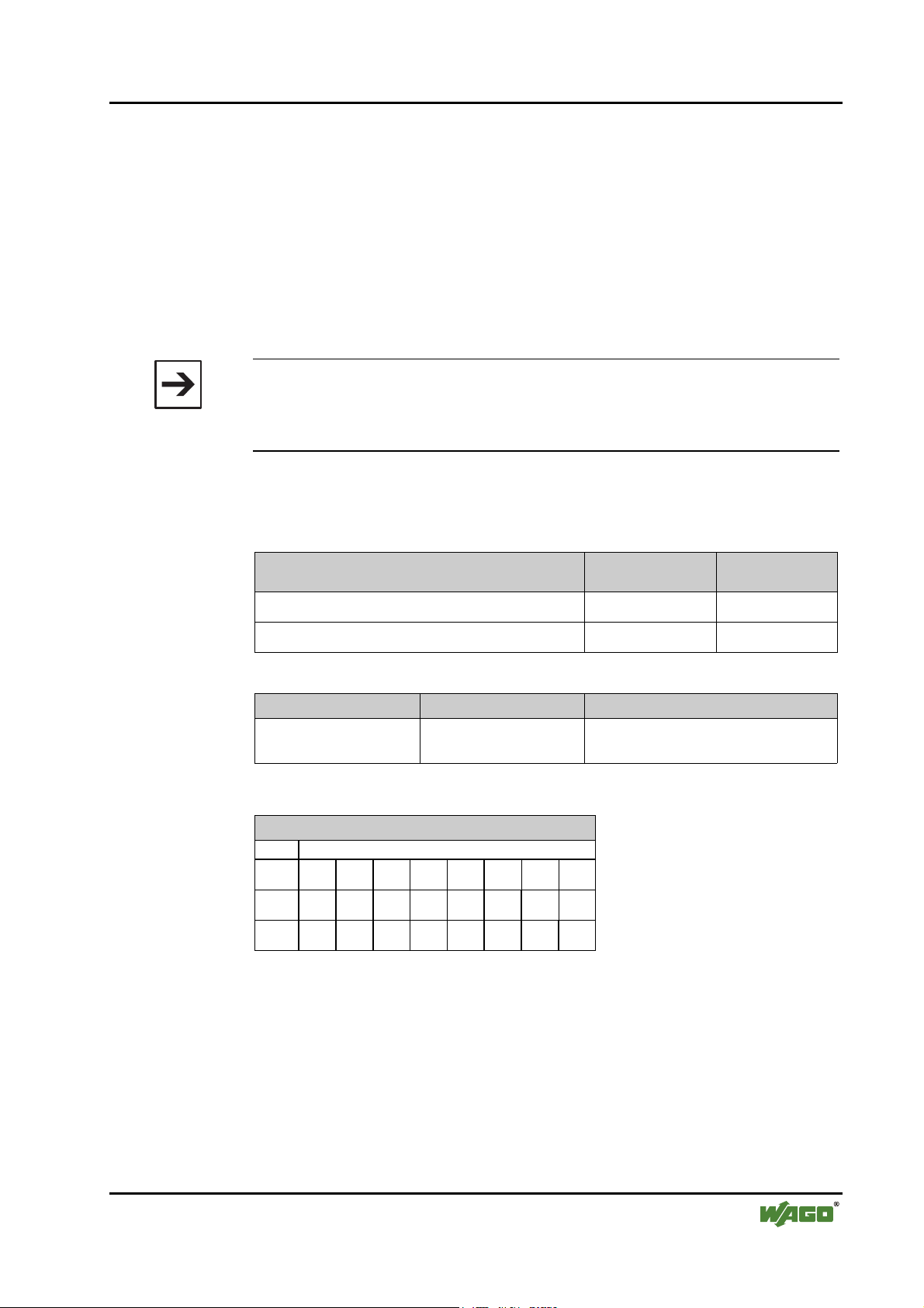
3.1.7 Configuring the process data channel
The process data channel serves for the communication between the coupler
and the higher ranking systems (Master or projecting and diagnosis PC).
This channel is allocated to the coupler. The fieldbus coupler 750-333 does not
use the process data channel.
Module Identification
hex
750-333 No process data channel 0x00 0
Identification
dec.
Note
The module „750-333 no process data channel“ should be configured as the
1st module.
D R A F T WAGO-I/O-SYSTEM 750
2001-02-27 PROFIBUS
Page 43
Fieldbus coupler / controller • 39
Fieldbus coupler 750-333
3.1.8 Configuration and parameterisation of I/O modules
3.1.8.1 Digital I/O modules
All binary I/O modules contain parameterisation information extended by 3
bytes, to serve, amongst others, for identification on the internal bus and the
structure of the mapping table. With diagnosis capable terminals the diagnosis
message can be suppressed or released for a channel or module. Binary outputs
offer the alternative to switch to parameterisable substitute values in the case
of a master failure.
Note
For simplification the tables only show the article number for the module
designation. The module „750-400“ thus corresponds to the module „750-400
2 DI/24 V DC/3.0 ms“
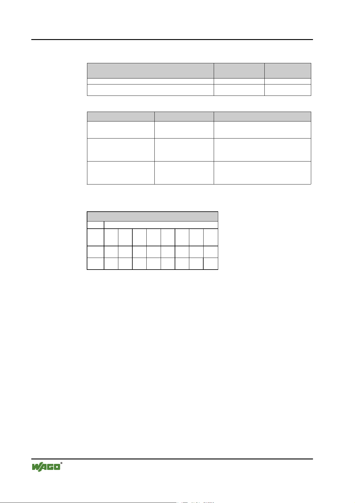
3.1.8.1.1 2 DI I/O modules
Module Identification
750-400, 750-401, 750-405, 750-406, 750-410,
750-411, 750-412
*750-400, *750-401, *750-405, *750-406, *750-410,
*750-411, *750-412
Parameter Value Meaning
I/O module is physically The I/O module process data is:
Parameter
Offset
Information
76543210
0
00Plug 00000
76543210
1
00000001
76543210
2
00000000
hex
0x10 16
0x00 0
plug fitted
not plug fitted - set to zero by the coupler
*)
*)
Default settings
- supplied by the I/O module
Identification
dec
Plug
5
Italic Cannot be changed
0
1
Module is physically not present
Module is physically present (default)
WAGO-I/O-SYSTEM 750 D R A F T
PROFIBUS 2001-02-27
Page 44

40 • Fieldbus coupler / controller
Fieldbus coupler 750-333
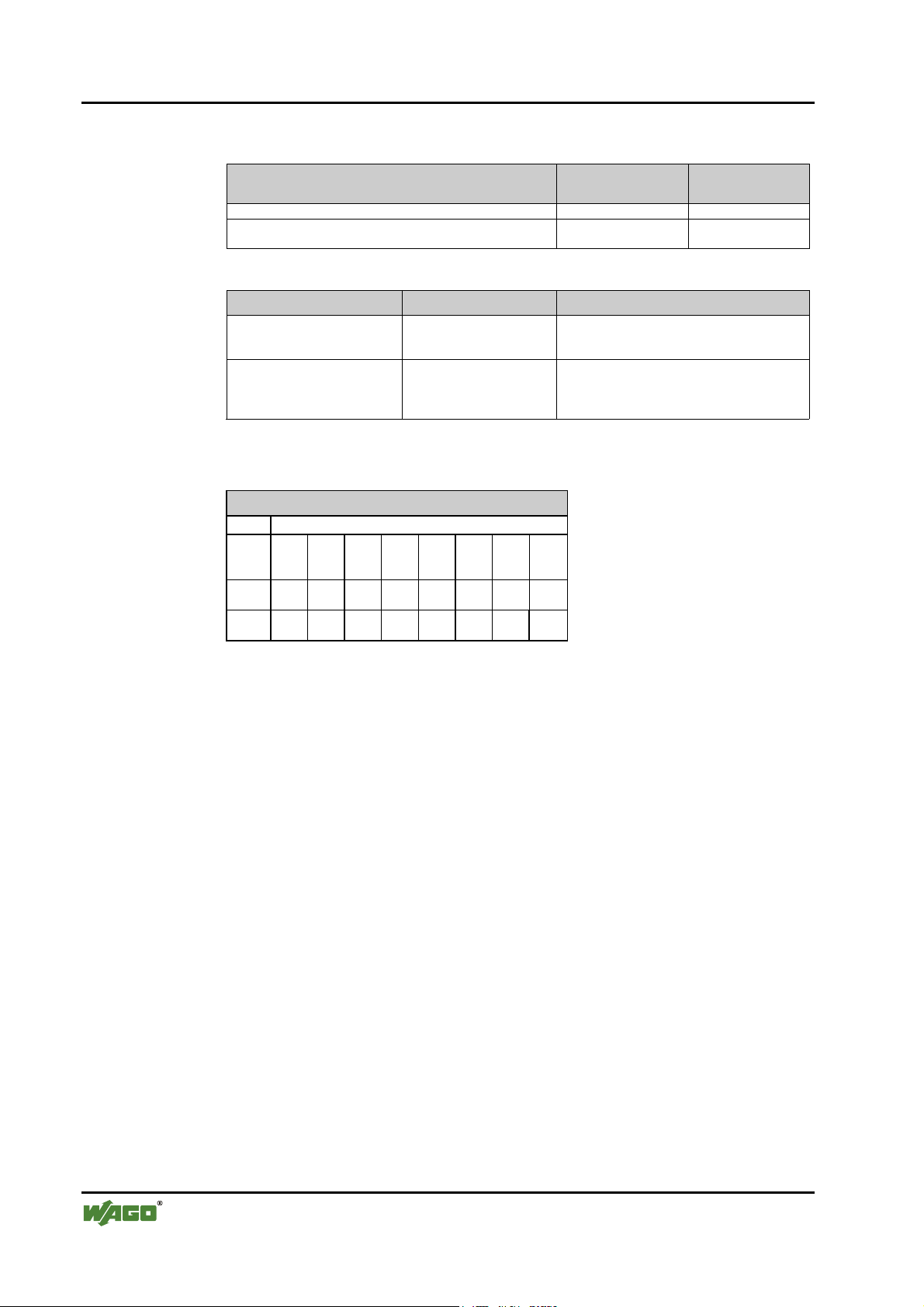
3.1.8.1.2 4 DI I/O modules
Module Identification
hex
750-402, 750-403, 750-408, 750-409, 750-414, 750-415,
0x10 16
Identification
dec
750-423, 750-422, 750-424
*750-402, *750-403, *750-408, *750-409, *750-414, *750-
0x00 0
415, *750-423, *750-422, *750-424
Parameter Value Meaning
I/O module is physically The I/O module process data is:
plug fitted
*)
- supplied by the I/O module
not plug fitted - Set to zero by the coupler
*)
Default settings
Parameter
Offset
Information
76543210
0
00Plug 00001
76543210
1
00000001
76543210
2
00000000
Plug
5
0
1
Module is physically not present
Module is physically present (default)
Italic Cannot be changed
D R A F T WAGO-I/O-SYSTEM 750
2001-02-27 PROFIBUS
Page 45

Fieldbus coupler / controller • 41
Fieldbus coupler 750-333
3.1.8.1.3 2 DI I/O modules modules with 1 bit diagn. per channel
Module Identification
hex
Identification
dec
750-419, 750-425 0x10 16
*750-419, *750-425 0x00 0
Parameter Value Meaning
I/O module is physically The I/O module process data is:
plug fitted
*)
- supplied by the I/O module
not plug fitted - set to zero by the coupler
Diagnosis channel x The diagnosis information of the corresponding
channel is
released - transmitted to PROFIBUS-DP master
*)
locked
*)
Default settings
- not transmitted to PROFIBUS-DP master
Parameter
Offset
Information
76543210
0
00Plug 0 Diag
76543210
1
En1
Diag
En0
01
00000101
76543210
2
00000000
Plug
5
DiagEn1
DiagEn0
0
1
3
0
1
2
0
1
Module is physically not present
Module is physically present (default)
Diagnosis idle run, short circuit on channel 2
locked
released
Diagnosis idle run, short circuit on channel 1
locked
released
Italic cannot be changed
WAGO-I/O-SYSTEM 750 D R A F T
PROFIBUS 2001-02-27
Page 46

42 • Fieldbus coupler / controller
Fieldbus coupler 750-333
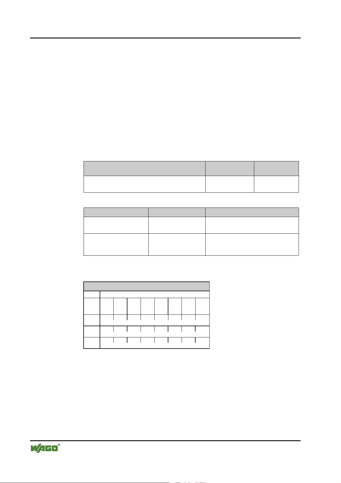
3.1.8.1.4 2 DO I/O modules
Module Identification
hex
750-501, 750-502, 750-509, 750-512, 750-513,
0x20 32
Identification
dec
750-514, 750-517
*750-501, *750-502, *750-509, *750-512, *750-513,
0x00 0
*750-514, *750-517
Parameter Value Meaning
I/O module is physically The I/O module process data is:
plug fitted
*)
- supplied to the I/O module
not plug fitted - ignored by the coupler
Substitute channel x
*)
0
1
If, in the case of a PROFIBUS-DP fault, the
switching of substitute values is enabled by the
bus coupler parameterisation, this data is transmitted to the periphery in the case of a fault.
*)
Default settings
Parameter
Offset
Information
76543210
0
00Plug 00000
76543210
1
00000010
76543210
2
000000SV1 SV0
Plug
SV0
SV0
5
0
1
0
1
Module is physically not present
Module is physically present (default)
Substitute value for channel 1
Substitute value for channel 2
Italic Cannot be changed
D R A F T WAGO-I/O-SYSTEM 750
2001-02-27 PROFIBUS
Page 47

Fieldbus coupler / controller • 43
Fieldbus coupler 750-333
3.1.8.1.5 2 DO I/O modules with 1 bit diagn. per channel
Module Identification
hex
Identification
dec
750-507, 750-522 0x20 32
*750-507, *750-522 0x00 0
Parameter Value Meaning
I/O module is physically The I/O module process data is:
plug fitted
*)
- supplied to the I/O module
not plug fitted - ignored by the coupler
Diagnosis channel x The diagnosis information of the corresponding
released
*)
channel is
- transmitted to PROFIBUS-DP master
locked - not transmitted to PROFIBUS-DP master
Substitute channel x
*)
0
1
If, in the case of a PROFIBUS-DP fault, the
switching of substitute values is enabled by the
bus coupler parameterisation, this data is transmitted to the periphery in the case of a fault.
*)
Default settings
Parameter
Offset
Information
76543210
0
00Plug 0 Diag
76543210
1
En1
Diag
En0
00
00000011
76543210
2
000000SV1 SV0
Plug
5
DiagEn0
DiagEn1
SV0
0
SV0
1
0
1
2
0
1
3
0
1
Module is physically not present
Module is physically present (default)
Diagnosis idle run, overload, short circuit on channel 1
lock
release
Diagnosis idle run, overload, short circuit on channel 2
locked
released
Substitute value for channel 1
Substitute value for channel 2
Italic Cannot be changed
WAGO-I/O-SYSTEM 750 D R A F T
PROFIBUS 2001-02-27
Page 48
44 • Fieldbus coupler / controller
Fieldbus coupler 750-333
3.1.8.1.6 2 DO I/O module with 2 bit diagn. per channel
Module Information
hex
Information
dec
750-506 0x20 32
*750-506 0x00 0
Parameter Value Meaning
I/O module is physically The I/O module process data is:
plug fitted
*)
- supplied to the I/O module
not plug fitted - ignored by the coupler
Diagnosis channel x The diagnosis information of the corresponding
released
*)
channel is
- transmitted to PROFIBUS-DP master
locked - not transmitted to PROFIBUS-DP master
Substitute channel x
*)
0
1
If, in the case of a PROFIBUS-DP fault, the
switching of substitute values is enabled by the
bus coupler parameterisation, this data is transmitted to the periphery in the case of a fault.
*)
Default settings
Parameter
Offset
Information
76543210
0
00Plug 0 Diag
76543210
1
En1
Diag
En0
01
00000011
76543210
2
000000SV1 SV0
Plug
5
DiagEn0
DiagEn1
SV0
0
SV0
1
0
1
2
0
1
3
0
1
Module is physically not present
Module is physically present (default)
Diagnosis idle run, short circuit, lower voltage on channel 1
locked
released
Diagnosis idle run, short circuit, lower voltage on channel 2
locked
released
Substitute value for channel 1
Substitute value for channel 2
Italic cannot be changed
D R A F T WAGO-I/O-SYSTEM 750
2001-02-27 PROFIBUS
Page 49

3.1.8.1.7 4 DO I/O modules
Fieldbus coupler / controller • 45
Fieldbus coupler 750-333
Module Identification
hex
Identification
dec
750-504, 750-516, 750-519 0x20 32
*750-504, *750-516, *750-519 0x00 0
Parameter Value Meaning
I/O module is physically The I/O module process data is:
plug fitted
*)
- supplied by the I/O module
not plug fitted - ignored by the coupler
Substitute channel x
*)
0
1
If, in the case of a PROFIBUS-DP fault, the
switching of substitute values is enabled by the
bus coupler parameterisation, this data is transmitted to the periphery in the case of a fault.
*)
Default settings
Parameter
Offset
Information
76543210
0
00Plug 00001
76543210
1
00000010
76543210
2
0000SV3 SV2 SV1 SV0
Plug
SV0
SV0
SV0
SV0
5
0
1
2
3
0
1
Module is physically not present
Module is physically present (default)
Substitute value for channel 1
Substitute value for channel 2
Substitute value for channel 3
Substitute value for channel 4
Italic Cannot be changed
WAGO-I/O-SYSTEM 750 D R A F T
PROFIBUS 2001-02-27
Page 50
46 • Fieldbus coupler / controller
Fieldbus coupler 750-333
3.1.8.1.8 2 DI/DO I/O module with 1 bit diagn. per channel
Module Identification
hex
Identification
dec
750-418 0x30 48
*750-418 0x00 0
Parameter Value Meaning
I/O module is physically The I/O module process data is:
plug fitted
*)
- supplied to the I/O module
not plug fitted - ignored by the coupler
Diagnosis channel x The diagnosis information of the corresponding
released
*)
channel is
- transmitted to PROFIBUS-DP master
locked - not transmitted to PROFIBUS-DP master
*)
Default settings
Parameter
Offset
Information
76543210
0
00Plug 0 Diag
76543210
1
En1
Diag
En0
01
00000111
76543210
2
00000000
Plug
5
DiagEn0
DiagEn1
0
1
2
0
1
3
0
1
Module is physically not present
Module is physically present (default)
Diagnosis idle run, overload, short circuit on channel 1
lock
release
Diagnosis idle run, overload, short circuit on channel 2
locked
released
Italic Cannot be changed
D R A F T WAGO-I/O-SYSTEM 750
2001-02-27 PROFIBUS
Page 51

Fieldbus coupler / controller • 47
Fieldbus coupler 750-333
3.1.8.1.9 Internal system supply module with diagnosis
Module Identification
hex
Identification
dec
750-610, 750-611 0x00 0
Parameter Value Meaning
I/O module is physically The I/O module process data is:
plug fitted
*)
- supplied by the I/O module
not plug fitted - set to zero by the coupler
Diagnosis field voltage loss
Diagnosis fuse blown
released
*)
The diagnosis information of the corresponding
channel is
- transmitted to PROFIBUS-DP master
locked - not transmitted to PROFIBUS-DP master
*)
Default settings
Parameter
Offset
Information
76543210
0
00Plug 0 Diag
76543210
1
En1
Diag
En0
00
00000000
76543210
2
00000000
Plug
5
DiagEn0
DiagEn1
0
1
0
2
1
0
3
1
Module is physically not present
Module is physically present (default)
Diagnosis field voltage failure info, lock
Diagnosis field voltage failure info., release
Diagnosis fuse failure info. lock
Diagnosis fuse failure info. release
Italic Cannot be changed
WAGO-I/O-SYSTEM 750 D R A F T
PROFIBUS 2001-02-27
Page 52
48 • Fieldbus coupler / controller
Fieldbus coupler 750-333
3.1.8.2 Analog I/O modules
All analog I/O modules have 2 bytes of extendable parameterisation information, which serves for identification on internal bus and the formation of a
mapping table.
Analog inputs are followed by 2 bytes reserved for future options. The diagnosis message can be suppressed or released for each individual channel by
means of modules capable of diagnostics.
Analog outputs have 4 byte parameterisation data. These are used to save the
substitute values for a maximum of 2 channels (2 words).
3.1.8.2.1 2 AI I/O modules
Module Identification
750-461, 750-462, 750-469, 750-465, 750-466, 750-467,
750-472, 750-474, 750-476, 750-478, 750-479, 750-480,
750-491
Parameter Value Meaning
I/O module is physically The I/O module process data is:
Diagnosis channel x The diagnosis information of the corresponding
Parameter
Offset
Information
76543210
0
00Plug 0 Diag
76543210
1
reserved
15 14 13 12 11 10 9 8
2
reserved
76543210
3
reserved
plug fitted
not plug fitted - set to zero by the coupler
released
locked - not transmitted to PROFIBUS-DP master
*)
*)
*)
Default settings
Diag
En1
En0
00
hex
0x51 81
- supplied by the I/O module
channel is
- transmitted to PROFIBUS-DP master
Identification
dec
Plug
5
DiagEn0
2
DiagEn1
3
Italic Cannot be changed
0
1
0
1
0
1
Module is physically not present
Module is physically present (default)
Diagnosis channel 1 locked
Diagnosis channel 1 released
Diagnosis channel 2 locked
Diagnosis channel 2 released
D R A F T WAGO-I/O-SYSTEM 750
2001-02-27 PROFIBUS
Page 53

3.1.8.2.2 4 AI I/O module
Fieldbus coupler / controller • 49
Fieldbus coupler 750-333
Module Identification
hex
Identification
dec
750-468 0x53 83
Parameter Value Meaning
I/O module is physically The I/O module process data is:
plug fitted
*)
- supplied by the I/O module
not plug fitted - set to zero by the coupler
Diagnosis channel x The diagnosis information of the corresponding
released
*)
channel is
- transmitted to PROFIBUS-DP master
locked - not transmitted to PROFIBUS-DP master
*)
Default settings
Parameter
Offset
Information
76543210
0
00Plug 0 Diag
76543210
1
En1
Diag
En0
Diag
En3
Diag
En2
reserved
15 14 13 12 11 10 9 8
2
reserved
76543210
3
reserved
Plug
5
DiagEn2
DiagEn3
DiagEn0
DiagEn1
0
1
2
3
0
1
0
1
0
1
0
1
0
1
Module is physically not present
Module is physically present (default)
Diagnosis channel 3 locked
Diagnosis channel 3 released
Diagnosis channel 4 locked
Diagnosis channel 4 released
Diagnosis channel 1 locked
Diagnosis channel 1 released
Diagnosis channel 2 locked
Diagnosis channel 2 released
Italic Cannot be changed
WAGO-I/O-SYSTEM 750 D R A F T
PROFIBUS 2001-02-27
Page 54

50 • Fieldbus coupler / controller
Fieldbus coupler 750-333
3.1.8.2.3 2 AO I/O modules
All analog modules have 6 bytes of extended parameterisation information and
offer the possibility of switching in parameterisable substitute values in the
case of a master failure.
Module Identification
750-550, 750-552, 750-554, 750-556 0x61 97
Parameter Value Meaning
I/O module is physically The I/O module process data is:
Diagnosis channel x The diagnosis information of the corresponding
Substitute value channel x
Parameter
Offset
Information
76543210
0
00Plug 00000
76543210
1
reserved
15 14 13 12 11 9 8 7
2
SubVal_Ch1_HB
76543210
3
SubVal_Ch1_LB
15 14 13 12 11 10 9 8
4
SubVal_Ch2_HB
76543210
5
SubVal_Ch2_LB
plug fitted*) - supplied by the I/O module
not plug fitted - ignored by the coupler
released - transmitted to PROFIBUS-DP master
*)
locked
0x0000 or 0x8000
0 or -32767
... 0x7FFF
... 32767
*)
Default settings
hex
channel is
- not transmitted to PROFIBUS-DP master
If, in the case of a PROFIBUS-DP fault, the
switching of substitute values is enabled by the
bus coupler parameterisation, this data is transmitted to the periphery in the case of a fault.
Identification
dec
Plug
5
SubVal_Ch1 0x0000
SubVal_Ch2 0x0000
Italic Cannot be changed
0
1
:
0xFFFF
:
0xFFFF
Module is physically not present
Module is physically present (default)
Substitute value channel 1
Substitute value channel 2
D R A F T WAGO-I/O-SYSTEM 750
2001-02-27 PROFIBUS
Page 55

3.1.8.3 Digital special modules
All digital special modules have 2 byte of extended parameterisation information, used for the identification on the internal bus and the creation of a mapping table.
With input modules (counter), 2 bytes follow which are reserved for future
options.
For output modules (PWM output) 6 byte parameterisation data follow, used
for saving the substitute values for a maximum of 2 channels (2 words).
3.1.8.3.1 Counter modules
Fieldbus coupler / controller • 51
Fieldbus coupler 750-333
Module Identification
750-404, 750-638 0xF2 242
Parameter Value Meaning
I/O module is physically The I/O module process data is:
Parameter
Offset
Information
76543210
0
00Plug 00000
76543210
1
reserved
15 14 13 12 11 9 8 7
2
reserved
76543210
3
reserved
Plug
5
Italic Cannot be changed
0
1
plug fitted*) - supplied by the I/O module
not plug fitted - set to zero by the coupler
*)
Default settings
Module is physically not present
Module is physically present (default)
hex
Identification
dec
WAGO-I/O-SYSTEM 750 D R A F T
PROFIBUS 2001-02-27
Page 56

52 • Fieldbus coupler / controller
Fieldbus coupler 750-333
3.1.8.3.2 PWM module
Module Identification
hex
Identification
dec
750-511 0xF2 242
Parameter Value Meaning
I/O module is physically The I/O module process data is:
plug fitted*) - supplied by the I/O module or
supplied to the I/O module
not plug fitted - set to zero by the coupler or
ignored by the coupler
Substitute value channel x
*)
0x0000
... 0x7FFF
If, in the case of a PROFIBUS-DP fault, the
switching of substitute values is enabled by the
bus coupler parameterisation, this data is transmitted to the periphery in the case of a fault.
*)
Default settings
Parameter
Offset
Information
76543210
0
00Plug 00000
76543210
1
10111101
15 14 13 12 11 9 8 7
2
reserved
76543210
3
00000000
15 14 13 12 11 9 8 7
4
SubVal_Ch1_HB
76543210
5
SubVal_Ch1_LB
15 14 13 12 11 10 9 8
6
SubVal_Ch2_HB
76543210
7
SubVal_Ch2_LB
Plug
5
SubVal_Ch1 0x0000
0
1
Module is physically not present
Module is physically present (default)
Substitute value channel 1
:
0xFFFF
SubVal_Ch2 0x0000
Substitute value channel 2
:
0xFFFF
Italic Cannot be changed
D R A F T WAGO-I/O-SYSTEM 750
2001-02-27 PROFIBUS
Page 57

Fieldbus coupler / controller • 53
3.1.8.4 Distance and Angle Messurment Modules
All interface modules for path and angle measurement have 2 bytes of extended parameterisation information used for the identification on internal bus
and the creation of the mapping table. 2 additional bytes follow which are reserved for future options.
3.1.8.4.1 SSI encoder interface
Fieldbus coupler 750-333
Module Identification
750-630 (Alternative) 0x93 147
750-630 (Standard) 0x95 149
Parameter Value Meaning
I/O module is physically The I/O module process data is:
Diagnosis channel x The diagnosis information of the corresponding
Parameter
Offset
Information
76543210
0
00Plug 00Diag
76543210
1
11000000
15 14 13 12 11 9 8 7
2
reserved
76543210
3
reserved
plug fitted*) - supplied by the I/O module or
not plug fitted - set to zero by the coupler or
released - transmitted to PROFIBUS-DP master
*)
locked
*)
Default settings
00
En0
hex
supplied to the I/O module
ignored by the coupler
channel is
- not transmitted to PROFIBUS-DP master
Identification
dec
Plug
5
DiagEn0
2
Italic Cannot be changed
0
1
0
1
Module is physically not present
Module is physically present (default)
Diagnosis locked (default)
Diagnosis released
WAGO-I/O-SYSTEM 750 D R A F T
PROFIBUS 2001-02-27
Page 58
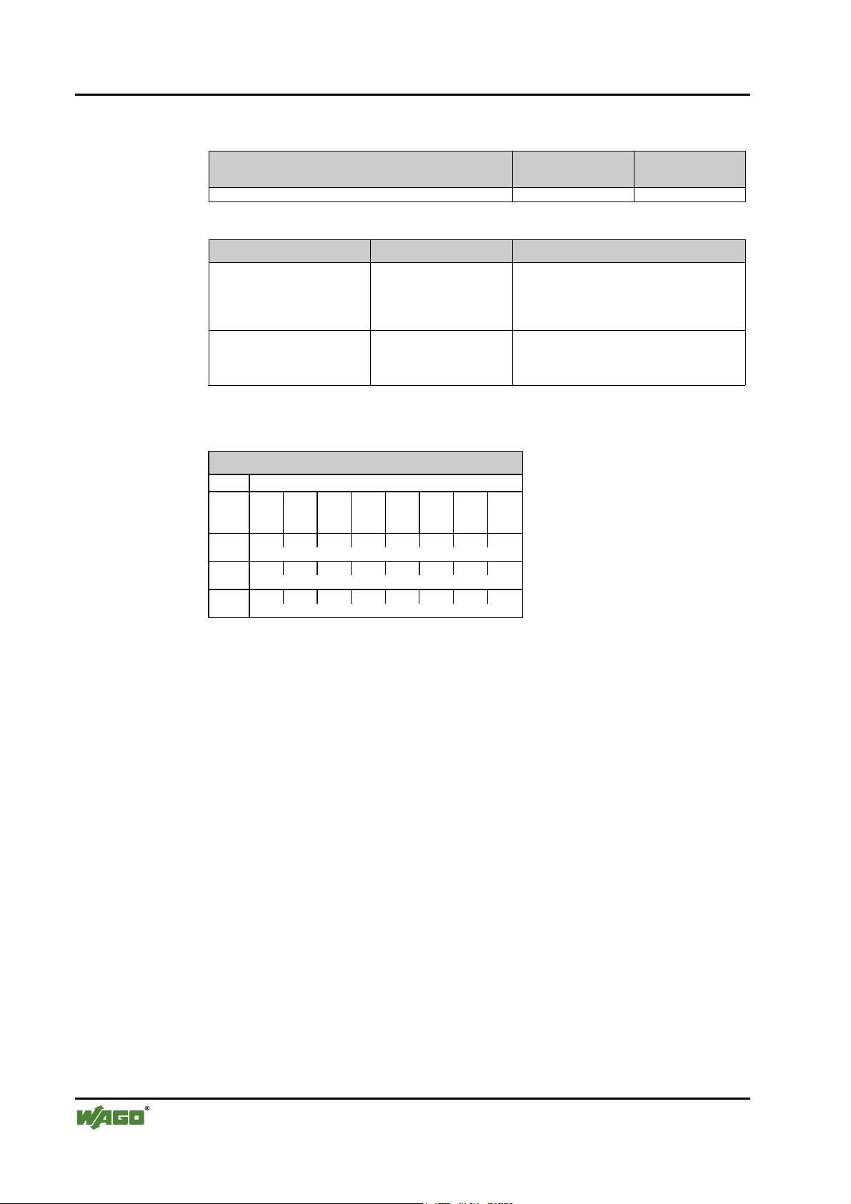
54 • Fieldbus coupler / controller
Fieldbus coupler 750-333
3.1.8.4.2 Incremental encoder interface
Module Identification
hex
Identification
dec
750-631, 750-637 0xB5 181
Parameter Value Meaning
I/O module is physically The I/O module process data is:
plug fitted*) - supplied by the I/O module or
supplied to the I/O module
not plug fitted - set to zero by the coupler or
ignored by the coupler
Diagnosis channel x The diagnosis information of the corresponding
channel is
released - transmitted to PROFIBUS-DP master
*)
locked
*)
Default settings
- not transmitted to PROFIBUS-DP master
Parameter
Offset
Information
76543210
0
00Plug 00Diag
00
En0
76543210
1
reserved
15 14 13 12 11 10 9 8
2
reserved
76543210
3
reserved
Plug
5
DiagEn0
2
0
1
0
1
Module is physically not present
Module is physically present (default)
Diagnosis locked (default)
Diagnosis released
Italic Cannot be changed
D R A F T WAGO-I/O-SYSTEM 750
2001-02-27 PROFIBUS
Page 59
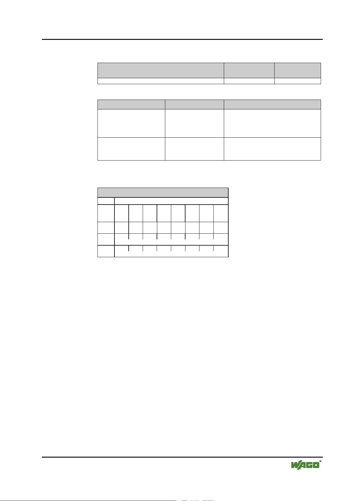
3.1.8.4.3 Digital impulse interface
Fieldbus coupler / controller • 55
Fieldbus coupler 750-333
Module Identification
hex
Identification
dec
750-635 0xB3 179
Parameter Value Meaning
I/O module is physically The I/O module process data is:
plug fitted*) - supplied by the I/O module or
supplied to the I/O module
not plug fitted - set to zero by the coupler or
ignored by the coupler
Diagnosis channel x The diagnosis information of the corresponding
channel is
released - transmitted to PROFIBUS-DP master
*)
locked
*)
Default settings
- not transmitted to PROFIBUS-DP master
Parameter
Offset
Information
76543210
0
00Plug 00Diag
00
En0
76543210
1
11000101
15 14 13 12 11 10 9 8
2
reserved
76543210
3
reserved
Plug
5
DiagEn0
2
0
1
0
1
Module is physically not present
Module is physically present (default)
Diagnosis locked (default)
Diagnosis released
Italic Cannot be changed
WAGO-I/O-SYSTEM 750 D R A F T
PROFIBUS 2001-02-27
Page 60

56 • Fieldbus coupler / controller
Fieldbus coupler 750-333
3.1.8.5 Serial interfaces
All serial interface modules have 2 bytes of extended parameterisation information used for the identification on internal bus and the creation of the mapping table. 2 additional bytes follow which are reserved for future options.
Module Identification
750-650, 750-651, 750-653, 750-654 (3 Byte) 0xB3 179
750-650, 750-651, 750-653, 750-654 (5 Byte) 0xB5 181
Parameter Value Meaning
I/O module is physically The I/O module process data is:
Diagnosis channel x The diagnosis information of the corresponding
Parameter
Offset
Information
76543210
0
00Plug 00Diag
76543210
1
reserved
15 14 13 12 11 10 9 8
2
reserved
76543210
3
reserved
plug fitted*) - supplied by the I/O module or
not plug fitted - set to zero by the coupler or
released - transmitted to PROFIBUS-DP master
*)
locked
*)
Default settings
00
En0
hex
supplied to the I/O module
ignored by the coupler
channel is
- not transmitted to PROFIBUS-DP master
Identification
dec
Plug
5
DiagEn0
2
Italic Cannot be changed
0
1
0
1
Module is physically not present
Module is physically present (default)
Diagnosis locked (default)
Diagnosis released
D R A F T WAGO-I/O-SYSTEM 750
2001-02-27 PROFIBUS
Page 61

3.1.9 Diagnosis
The slave diagnosis of the bus coupler now comprises of a 6 byte standard diagnosis, a 9 byte identification diagnosis, a 7 byte device status and an up to
42 byte channel based diagnosis.
In the reply telegram of the diagnosis selection the identification based diagnosis and the device status are transmitted together with the standard diagnosis.
This can be followed by up to 14 channel based diagnosis messages (3 byte per
message).
Byte
0
Fieldbus coupler / controller • 57
Fieldbus coupler 750-333
1
2
3
4
5
6
7
:
14
15
Station status 1 to 3
PROFIBUS-DP master address
Manufacturer identification
Identification based diagnosis
:
:
Device status
21
22
63
WAGO-I/O-SYSTEM 750 D R A F T
PROFIBUS 2001-02-27
Channel based diagnosis
(3 bytes per channel)
Page 62
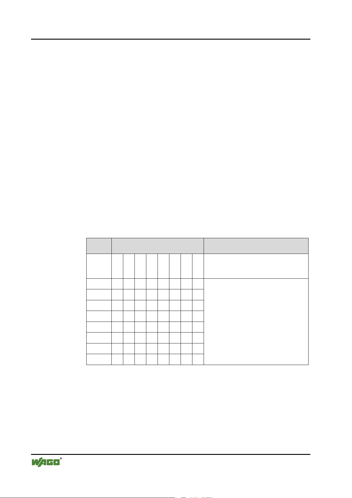
58 • Fieldbus coupler / controller
Fieldbus coupler 750-333
3.1.9.1 Station status 1 to 3
see EN 50170
3.1.9.2 PROFIBUS-DP master address
The PROFIBUS-DP master address is located in byte 3 of the slave diagnosis
and includes the address of the master which has parameterised the station and
which has read and write access.
3.1.9.3 Manufacturer‘s identification
The manufacturer’s identification is located in byte 4 and 5 and includes a 16
bit code, which serves for the identification of the device or the device class.
3.1.9.4 Identification based diagnosis
The identification based diagnosis comprises of a bit field, which contains one
bit of information for each connected module. The individual bit provides evidence about the current operating status. A 0 means no fault, a 1 indicates a
faulty module condition. The bus coupler can be equipped with up to 63 modules, so that the identification based diagnosis including the header covers 9
bytes from byte 6 to byte 14.
Byte Information Meaning
6
7
8
9
10
11
12
13
14
01001001Header byte
(9 byte identification based diagnosis
incl. header)
76543210
15 14 13 12 11 10 9 8
23 22 21 20 19 18 17 16 Diagnosis allocation to
31 30 29 28 27 26 25 24 I/O module n (n=1 ... 63)
39 38 37 36 35 34 33 32 Coupler (n=0)
47 46 45 44 43 42 41 40
55 54 53 52 51 50 49 48
63 62 61 60 59 58 57 56
D R A F T WAGO-I/O-SYSTEM 750
2001-02-27 PROFIBUS
Page 63
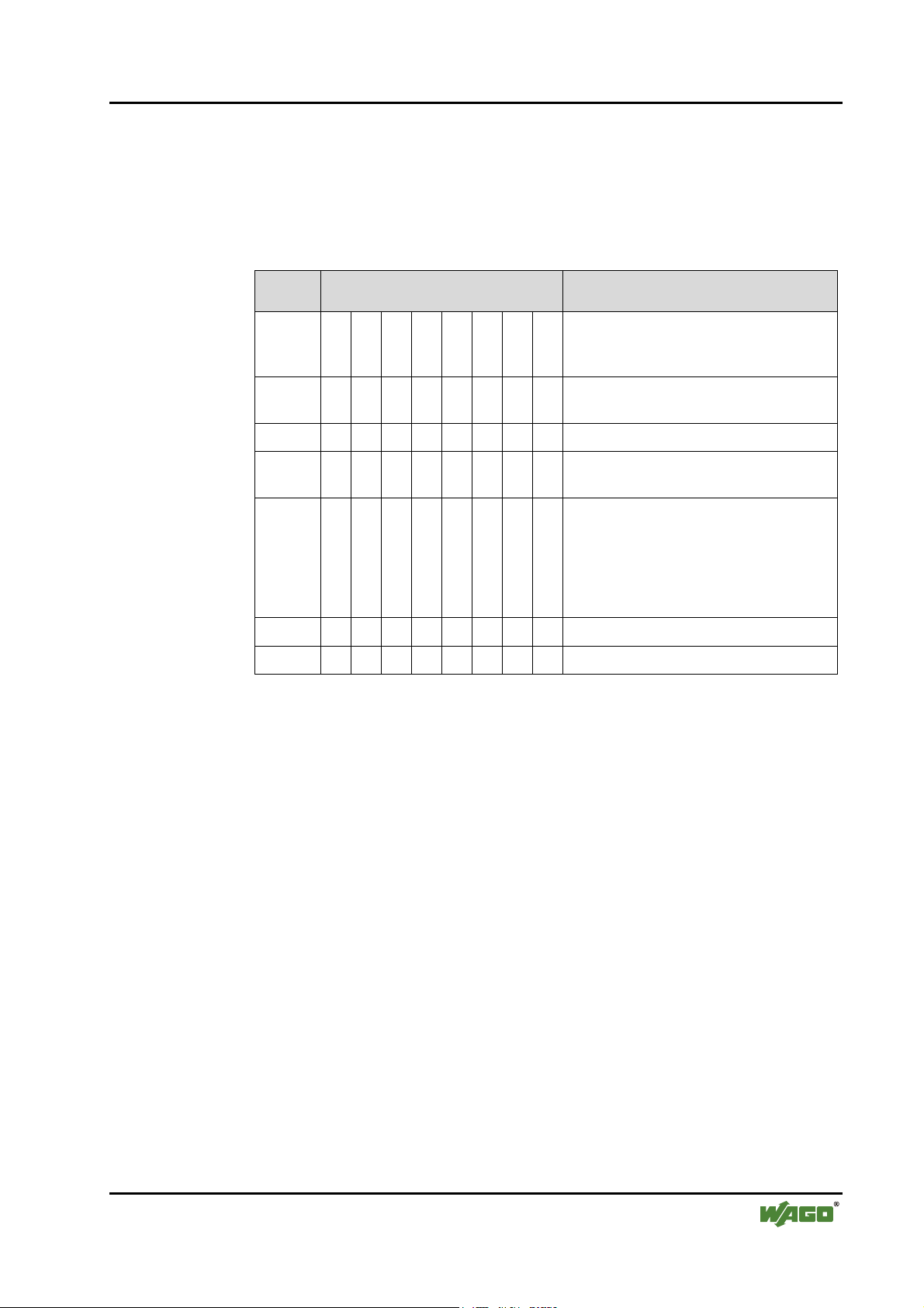
3.1.9.5 Device status
The device status encompasses 7 bytes including the required overhead and
transmits status information of an internal nature and relating to the I/O module (internal bus), PROFIBUS-DP and the PFC-RTS to the master or the
higher ranking controls.
Byte Information Meaning
Fieldbus coupler / controller • 59
Fieldbus coupler 750-333
15
16
17
18
19
20
21
00000111Header byte
(7 byte status information
incl. header)
10100000Status type
(manufacturer specific device status)
00000000Slot number 0
00000000Status differentiation
(none)
qqnnnnnnStatus message
q – Status source
'00' Internal status
'01' Internal bus status
'10' PROFIBUS DP status
n – Status number
xxxxxxxxStatus argument
00000000Reserved
WAGO-I/O-SYSTEM 750 D R A F T
PROFIBUS 2001-02-27
Page 64
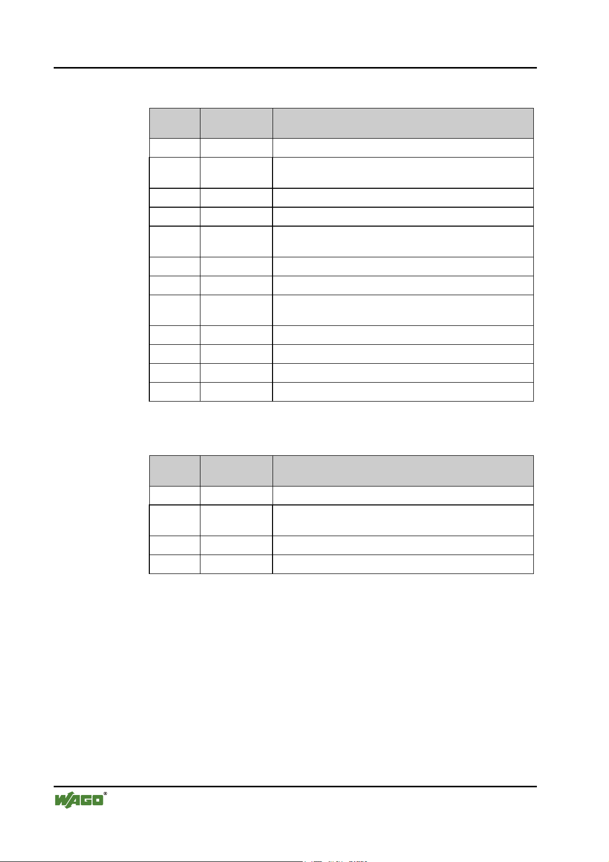
60 • Fieldbus coupler / controller
Fieldbus coupler 750-333
3.1.9.5.1 Internal status messages and arguments
Status
message
0x00 0x00 No fault
0x01 0x00 EEPROM check sum fault / check sum fault in the parameter
0x01 0x01 Overflow inline code buffer
0x01 0x02 Unknown data type
0x01 0x03 Module type of the flash program memory could not be de-
0x01 0x04 Fault when writing in the FLASH memory
0x01 0x05 Fault when deleting the FLASH memory
0x01 0x06 Changed I/O modules configuration determined following
0x01 0x07 Fault when writing in the serial EEPROM
0x01 0x08 Invalid firmware
0x02 0x00 Incorrect table entry
0x07 n Non-supported modules at position n (n = 1...63)
Status
argument
Description
area of the flash
termined / is incorrect
AUTORESET
3.1.9.5.2 Internal bus status messages and arguments
Status
message
0x63 0xFF At least one module cannot interpret an internal bus command
0x64 0x00 A data fault or an internal bus interruption exists behind the
0x64 n An internal bus interruption exists behind the module n
0x65 n Fault in the register communication with module n
Status
argument
Description
bus coupler
D R A F T WAGO-I/O-SYSTEM 750
2001-02-27 PROFIBUS
Page 65

Fieldbus coupler / controller • 61
Fieldbus coupler 750-333
3.1.9.5.3 PROFIBUS-DP status messages and arguments
Status
message
0x81 0x01 Insufficient parameterisation data configuration data
0x81 0x02 Too much parameterisation data
0x82 n n. parameter byte faulty
0x83 0x01 Insufficient configuration data
0x83 0x02 Too much configuration data
0x84 n n. configuration byte (module) faulty
0x85 0x01 maximum input data length exceeded
0x85 0x02 maximum output data length exceeded
0x86 0x01 Compilate buffer overflow for DP process image
0x86 0x02 Compilate buffer overflow for PFC process image
Status
argument
Description
WAGO-I/O-SYSTEM 750 D R A F T
PROFIBUS 2001-02-27
Page 66
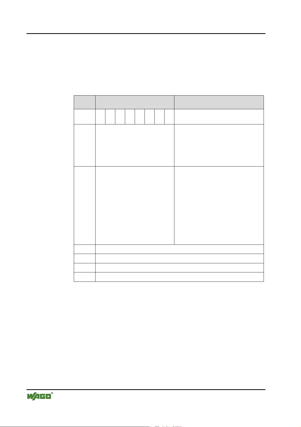
62 • Fieldbus coupler / controller
Fieldbus coupler 750-333
3.1.9.6 Channel based diagnosis
The channel based diagnosis is intended for detailing the identification based
diagnosis. A structure is appended to each device status per faulty slot which
comprises of a header byte, a byte, the channel type supplying the channel
number and a third byte, which describes the fault type and the channel organisation.
Byte Information Meaning
22
23
24
25-27
28-30
1 0 x x x x x x Header channel based diagnosis
(x: 1 to 63, slots of the module)
aaxxxxxxChannel type (a) and
channel number x: 0 to 3
0 1 Input channel
1 0 Output channel
1 1 Input / output channel
t t t xxxxxChannel type (t) and
fault type (x)
0 0 0 No allocation
001 1 Bit
010 2 Bit
011 4 Bit
100 1 Byte
101 1 Word
110 2 Words
Next channel based diagnosis message (as byte 22 – 24)
Next channel based diagnosis message (as byte 22 – 24)
...
61-63
...
Last displayable channel based diagnosis message (such as byte 22 – 24)
D R A F T WAGO-I/O-SYSTEM 750
2001-02-27 PROFIBUS
Page 67

Fieldbus coupler / controller • 63
Fieldbus coupler 750-333
3.1.9.6.1 Fault types of I/O modules with diagnostic capability
The fault types refer to standardised types.
Fault
type
0 Not specified
1 Short circuit
2 Low voltage
3 High voltage
4Overload
5 Over temperature
6 Line break
7 Upper limit value exceeded
8 Lower limit value exceeded
9Fault
10 ... 15 Reserved
16 ... 31 Manufacturer specific
17 Field voltage fault
18 Fuse fault
19 Buffer overflow
Meaning
20 Check sum fault
21 Parity fault
22 Receive Timeout (partner)
23 Receive Timeout
26 SSI_IN fault
27 SSI FRAME fault
31 I/O module fault
WAGO-I/O-SYSTEM 750 D R A F T
PROFIBUS 2001-02-27
Page 68

64 • Fieldbus coupler / controller
Fieldbus coupler 750-333
3.1.9.6.2 I/O modules fault cases
Article number
750-418, 750-419,
750-507, 750-522
750-506 '001 0.0001'
750-461, 750-469 '101 0.0110'
750-462, 750-465,
750-466, 750-472,
750-474, 750-479,
750-480
750-610, 750-611, '001 1.0001'
750-630 '110 1.1010'
Channel
type
'001 0.1001' Fault (line break, overload or short
'101 0.0111'
Fault type Meaning
0.0010'
0.0110'
0.1001'
0.1000'
1.0000'
1.1111'
0.1000'
1.0000'
1.1111'
1.0010'
1.1011'
1.0000'
1.1111'
circuit)
Short circuit
Lower voltage
Line break
Error
Line break
Lower limit value gone below
Parameterisation fault
I/O module fault
Lower limit value gone below
Upper limit value exceeded
Parameterisation fault
I/O module fault
Field voltage fault
Fuse fault
SSI_IN fault (external fault)
SSI FRAME fault
Parameterisation fault
I/O module fault
750-635, 750-637 '110 0.1001'
1.0000'
1.1111'
750-650, 750-651,
750-653, 750-654
'110
('000)
0.1001'
1.0000'
1.1111'
Error
Parameterisation fault
I/O module fault
Buffer overflow
Parameterisation fault
I/O module fault
D R A F T WAGO-I/O-SYSTEM 750
2001-02-27 PROFIBUS
Page 69

3.1.10 LED signalling
The coupler possesses several LED’s for on site signalling of the coupler operating status or the complete node
PROFIBUS
A
RUN
B
BF
DIA
BUS
24V
Fieldbus coupler / controller • 65
Fieldbus coupler 750-333
C
D
0V
I/O
Fig. 3-10: Display elements 750-333 g012106x
3.1.10.1 Blink code
Detailed fault messages are displayed with the aid of a blink code. A fault is
cyclically displayed with up to 3 blink sequences.
• The first blink sequence (approx. 10 Hz) starts the fault display.
• The second blink sequence (approx. 1 Hz) following a pause. The number
of blink pulses indicates the fault code.
• The third blink sequence (approx. 1 Hz) follows after a further pause. The
number of blink pulses indicates the fault argument.
++
WAGO-I/O-SYSTEM 750 D R A F T
PROFIBUS 2001-02-27
Page 70
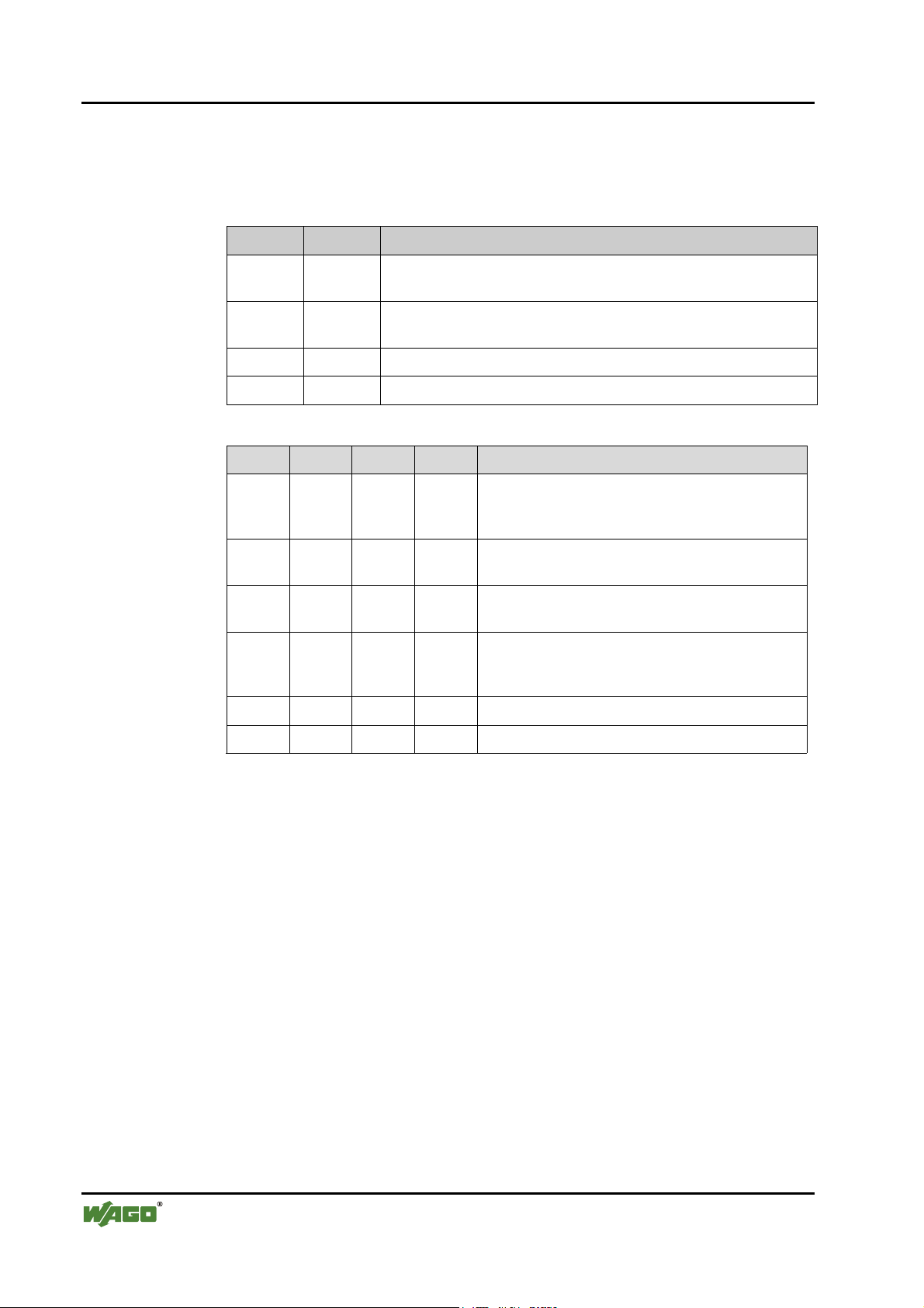
66 • Fieldbus coupler / controller
Fieldbus coupler 750-333
3.1.10.2 Fieldbus status
The upper four LED´s signal the operating conditions of the PROFIBUS
communication.
LED Colour Meaning
RUN green The 'RUN' LED indicates to the user if the fieldbus coupler is per-
BF red The 'BF' LED indicates that the communication functions via the
DIA red The 'DIA' LED indicates an external diagnosis.
BUS red The 'BUS' LED signals a projecting fault.
RUN BF DIA BUS Meaning
off off off off No operating voltage to the coupler (status LED of
fectly initialised.
PROFIBUS.
the bus coupler supply does not light up) or a
hardware fault is present.
on on * off PROFIBUS interface started, baud rate was not yet
recognised.
on blinks * off Baud rate recognised, station not yet parameterised
and configured.
on blinks on blinks
cyclically
on off * off The coupler is exchanging data.
on * on * The coupler signals an existing diagnosis.
* Not relevant
Slave was incorrectly projected.
Fault message via blink code
D R A F T WAGO-I/O-SYSTEM 750
2001-02-27 PROFIBUS
Page 71

Fieldbus coupler / controller • 67
Fieldbus coupler 750-333
3.1.10.3 Fault message via blink code of the BUS-LED
Fault argument Fault description
Fault code 1: Fault in parameterisation telegram
1 Insufficient parameterisation data
2 Excessive parameterisation data
Fault code 2: Fault in parameterisation telegram
n Faulty parameterised byte n
Fault code 3: Fault in configuration telegram
1 Insufficient configuration data
2 Excessive configuration data
Fault code 4: Fault in configuration telegram
n Configuration byte (module) n is faulty
Fault code 5: Fault in the data length
1 maximum input data length exceeded
2 maximum output data length exceeded
Fault code 6: Compilate buffer overflow
1 Compilate buffer overflow for DP process image
WAGO-I/O-SYSTEM 750 D R A F T
PROFIBUS 2001-02-27
Page 72

68 • Fieldbus coupler / controller
Fieldbus coupler 750-333
3.1.10.4 Node status
The 'I/O' LED indicates the node operation and signals faults occurring.
I/O Meaning
green Data cycle on the internal bus
off No data cycle on the internal bus
red Coupler hardware defective
red
blinks
red
When starting: internal bus is initialised
During operation: general internal bus fault
Fault message during internal bus reset and internal fault:
blinks cyclically
orange FLASH access to bus coupler firmware
The coupler starts after switching on the supply voltage. The "I/O" LED
flashes red. Following a fault free run up the "I/O" LED changes to green
steady light.
In the case of a fault the "I/O" LED continues blinking red. The fault is cyclically displayed with the blink code.
Versorgungsspannung
einschalten
Koppler-Hochlauf
“I/O”-LED blinkt
Fehler
Nein
Ja
“I/O”-LED
1. Blinksequenz
(leitet opt. Anzeige eines Fehlers ein)
1. Pause
“I/O”-LED
“I/O”-LED an
Feldbusstart
2. Blinksequenz
Fehlercode
“I/O”-LED
3. Blinksequenz
Fehlerargument
(Anzahl Blinkimpulse)
2. Pause
(Anz. Blinkimp.)
Fig. 3-11: Signalling the LED's node status g012111d
After overcoming a fault restart the coupler by switching off and on the supply
voltage.
D R A F T WAGO-I/O-SYSTEM 750
2001-02-27 PROFIBUS
Page 73

Fieldbus coupler / controller • 69
Fieldbus coupler 750-333
3.1.10.5 Fault message via the blink code of the I/O LED
Fault argument Fault description
Fault code 1: Hardware and configuration fault
0 EEPROM check sum fault / check sum fault in parameter area of the
flash memory
1 Overflow of the internal buffer memory for the inline code
2 Unknown data type
3 Module type of the flash program memory could not be determined /
is incorrect
4 Fault during writing in the flash memory
5 Fault when deleting the FLASH memory
6 Changed I/O module configuration found after AUTORESET
7 Fault when writing in the serial EEPROM
8 Invalid firmware
Fault code 2: Fault in programmed configuration
0 Incorrect table entry
Fault code 3: Internal bus command fault
0 I/O module(s) has (have) identified internal bus command as incor-
rect
Fault code 4: Internal bus data fault
0 Data fault on internal bus or
Internal bus interruption on coupler
n* (n>0) Internal bus interrupted after I/O module n
Fault code 5: Register communication fault
n* Internal bus fault during register communication with the I/O module
n
Fault code 7: I/O module not supported
n* I/O module not supported at position n
* The number of blink pulses (n) indicates the position of the I/O module. I/O modules
without data are not counted (e.g. supply module without diagnosis)
Example: the 13th I/O module is removed.
1. The "I/O" LED generates a fault display with the first blink sequence (approx. 10 Hz).
2. The first pause is followed by the second blink sequence (approx. 1 Hz). The "I/O"
LED blinks four times and thus signals the fault code 4 (internal bus data fault).
3. The third blink sequence follows the second pause. The "I/O ERR" LED blinks twelve
times. The fault argument 12 means that the internal bus is interrupted after the 12
I/O module.
WAGO-I/O-SYSTEM 750 D R A F T
PROFIBUS 2001-02-27
th
Page 74

70 • Fieldbus coupler / controller
Fieldbus coupler 750-333
3.1.10.6 Supply voltage status
LED Colour Meaning
A green Status of the operating voltage – system
C green Status of the operating voltage – power jumper contacts
There are two green LED’s in the coupler supply section to display the supply
voltage. The left LED (A) indicates the 24 V supply for the coupler. The right
hand LED (C) signals the supply to the field side, i.e. the power jumper contacts.
D R A F T WAGO-I/O-SYSTEM 750
2001-02-27 PROFIBUS
Page 75
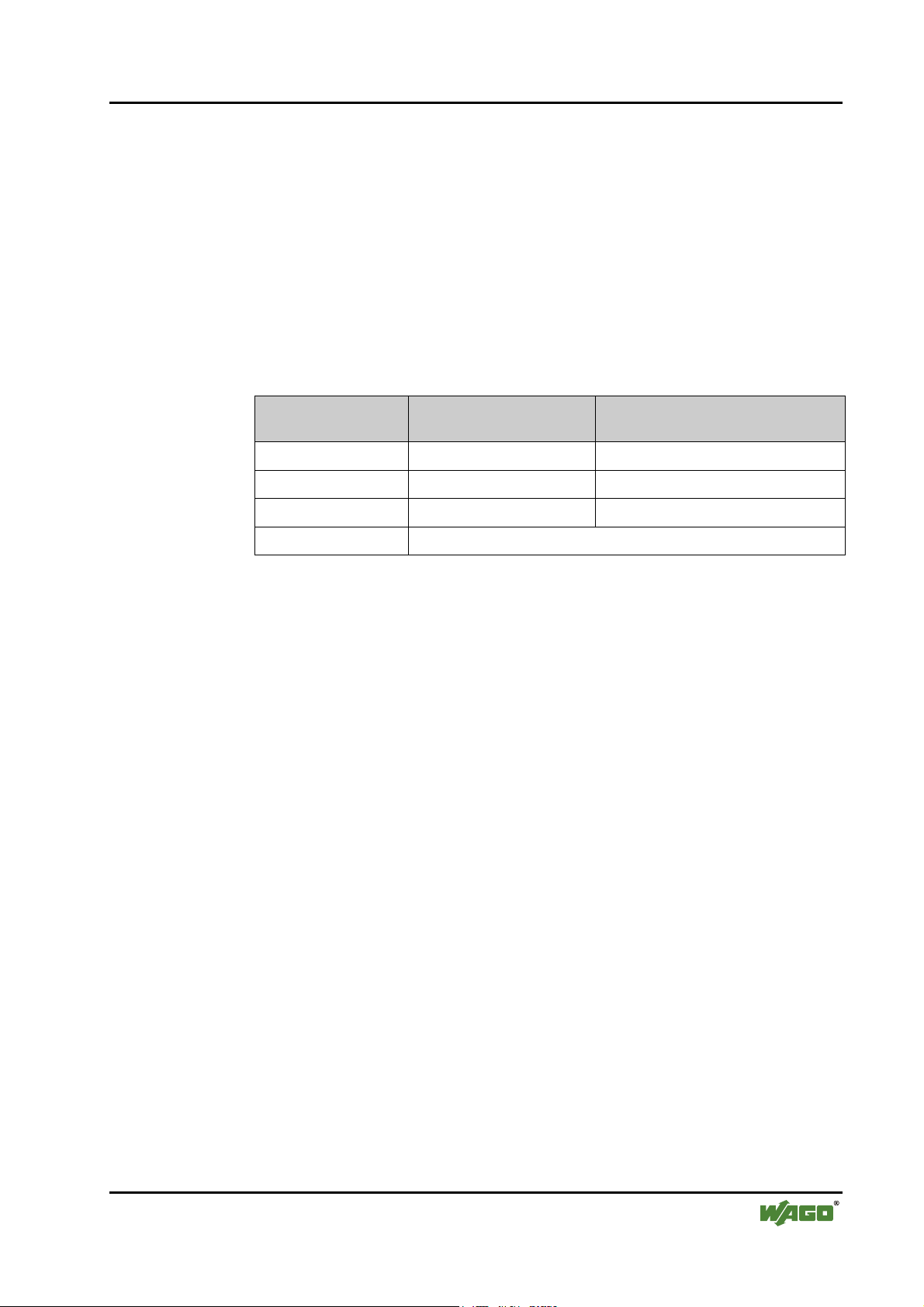
3.1.11 Fault behaviour
3.1.11.1 Fieldbus failure
A fieldbus failure has occurred when the master is switched off or the bus cable is interrupted. A fault in the master can also lead to a fieldbus failure.
The red "BF" LED lights up.
The failure of the fieldbus can activate the parameterisable substitute value of
the I/O modules. During projecting of the inputs and outputs a substitute value
can be laid down for each channel.
Fieldbus coupler / controller • 71
Fieldbus coupler 750-333
Substitute value
strategy
Minimum value 0 0 or 4 mA, 0 V
Maximum value 1 20 mA, 10 V
Substitute value 0 or 1 0/4 ... 20 mA, -10 ... +10 V
Stop internal bus Behaviour determined by I/O module
Value (bit orientated)
Digital output modules
Value (byte orientated)
Analog output modules
The value is entered in the output process image by the coupler. With I/O
modules with byte orientated data width, e.g. the pulse width module, the substitute value is determined via the value area.
As soon as the fieldbus is active the process data is transmitted and the output
correspondingly set in the nodes.
WAGO-I/O-SYSTEM 750 D R A F T
PROFIBUS 2001-02-27
Page 76

72 • Fieldbus coupler / controller
Fieldbus coupler 750-333
3.1.11.2 Internal bus fault
An internal bus fault is created, for example, if an I/O module is removed. If
this fault occurs during operation the output modules behave in the same manner as an I/O module stop. The input process image is set in accordance with
the projected strategy.
The "I/O" LED blinks red. The slave generates a detailed fault message.
Once the internal bus fault has been overcome the coupler starts up automatically in accordance with the parameterised restart routine. The process data
transfer is then restarted and the outputs reset in the nodes.
D R A F T WAGO-I/O-SYSTEM 750
2001-02-27 PROFIBUS
Page 77
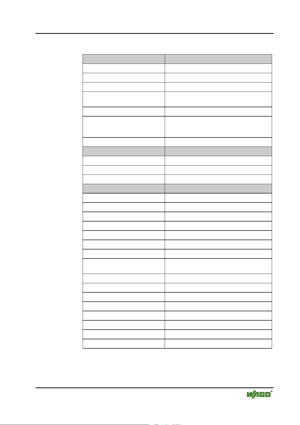
3.1.12 Technical data
System data
Number of I/O modules 96 with repeater
Number of I/O points approx. 6000 (master dependent)
Transmission medium Cu cable in accordance with EN 50170
Bus segment length 100 m ... 1200 m
Transmission rate 9.6 kBaud ... 12 MBaud
Fieldbus coupler / controller • 73
Fieldbus coupler 750-333
(baud rate dependent / cable dependent)
Transmission time with 10 modules
each with 32 DI and 32 DO, 12
typically 1 ms
max. 3.3 ms
MBaud
Bus connection 1 x D-SUB 9; socket
Standards and approvals
UL (UL508) E175199
Standard EN 50 170
Conformity marking CE
Technical data
Number of I/O modules 63
Protocol DP / DPV1
Input process image max. 128 Byte
Output process image max. 128 Byte
Configuration via PC or controls
Voltage supply DC 24 V (-15 % / + 20 %)
Input current
max
Internal system supply module effi-
500 mA at 24 V
87 %
ciency
Internal power consumption 200 mA at 5 V
Total current for I/O modules 1800 mA at 5 V
Voltage via power jumper contacts DC 24 V (-15 % / + 20 %)
Current via power jumper contact
max
Dimensions (mm) B x H x T 51 x 65* x 100 (*from top edge of mounting rail)
Weight approx. 195 g
EMC interference resistance as per EN 50082-2 (95)
EMC interference transmission as per EN 50081-2 (94)
WAGO-I/O-SYSTEM 750 D R A F T
PROFIBUS 2001-02-27
DC 10 A
Page 78

74 • Fieldbus coupler / controller
Fieldbus Controller 750-833
3.2 Fieldbus Controller 750-833
This chapter includes:
3.2.1 Description ......................................................................................76
3.2.2 Hardware.........................................................................................77
3.2.2.1 View .........................................................................................77
3.2.2.2 Device supply...........................................................................78
3.2.2.3 Fieldbus connection..................................................................79
3.2.2.4 Display elements ......................................................................80
3.2.2.5 Station address..........................................................................81
3.2.2.6 Configuration and programming interface...............................81
3.2.2.7 Operating mode switch.............................................................82
3.2.3 Operating system.............................................................................83
3.2.3.1 Run-up......................................................................................83
3.2.3.2 PLC cycle .................................................................................83
3.2.4 Process image..................................................................................85
3.2.4.1 Local process image .................................................................85
3.2.4.2 Allocation of the input and output data....................................86
3.2.5 Configuration ..................................................................................87
3.2.5.1 GSD files..................................................................................88
3.2.5.2 Identification bytes...................................................................89
3.2.5.3 Example....................................................................................92
3.2.6 Parameterisation of the controllers..................................................94
3.2.7 Configuration of the process data channels ....................................96
3.2.8 Configuration and parameterisation of I/O modules.......................97
3.2.8.1 Digital I/O modules..................................................................97
3.2.8.1.1 2 DI I/O modules......................................................................97
3.2.8.1.2 4 DI I/O modules......................................................................98
3.2.8.1.3 2 DI I/O modules with 1 bit diagn. per channel .......................99
3.2.8.1.4 2 DO I/O modules ..................................................................100
3.2.8.1.5 2 DO I/O modules with 1 bit diagn. per channel....................101
3.2.8.1.6 2 DO I/O modules with 2 bit diagn. per channel....................102
3.2.8.1.7 4 DO I/O modules ..................................................................103
3.2.8.1.8 2 DI/DO I/O module with 1 bit diagn. per channel................104
3.2.8.1.9 Potential supply modules with diagnosis ...............................105
3.2.8.2 Analog I/O modules ...............................................................106
3.2.8.2.1 2 AI modules ..........................................................................106
3.2.8.2.2 4 AI module............................................................................107
3.2.8.2.3 2 AO modules.........................................................................108
3.2.8.3 Special digital modules ..........................................................109
3.2.8.3.1 Counter modules ....................................................................109
3.2.8.3.2 PWM module .........................................................................110
3.2.8.4 Distance and Angle Messurment Modules.............................111
3.2.8.4.1 SSI generator interface ...........................................................111
3.2.8.4.2 Incremental encoder interface ................................................112
3.2.8.4.3 Digital impulse interface ........................................................113
3.2.8.5 Serial interfaces ......................................................................114
D R A F T WAGO-I/O-SYSTEM 750
2001-02-27 PROFIBUS
Page 79

Fieldbus coupler / controller • 75
Fieldbus Controller 750-833
3.2.9 Diagnosis.......................................................................................115
3.2.9.1 Stations status 1 to 3...............................................................116
3.2.9.2 PROFIBUS-DP master address..............................................116
3.2.9.3 Manufacturer identification....................................................116
3.2.9.4 Identification based diagnosis ................................................116
3.2.9.5 Device status ..........................................................................117
3.2.9.5.1 Internal status messages and arguments.................................118
3.2.9.5.2 Internal bus status messages and arguments ..........................118
3.2.9.5.3 PROFIBUS-DP status messages and arguments....................119
3.2.9.5.4 PLC-RTS status messages and arguments .............................119
3.2.9.6 Channel based diagnosis ........................................................120
3.2.9.6.1 Fault types of I/O modules with diagnostic capability...........121
3.2.9.6.2 I/O modules fault cases ..........................................................122
3.2.10 Commissioning (start-up) with WAGO-I/O-PRO ........................123
3.2.11 LED signalling ..............................................................................124
3.2.11.1 Blink code ..............................................................................124
3.2.11.2 Fieldbus status........................................................................125
3.2.11.3 Fault message by means of blink code of the BUS-LED.......126
3.2.11.4 Node status .............................................................................127
3.2.11.5 Fault message via blink code from the I/O-LED....................128
3.2.11.6 Supply voltage status..............................................................129
3.2.12 Fault behaviour .............................................................................129
3.2.12.1 Fieldbus failure.......................................................................129
3.2.12.2 Internal bus fault.....................................................................130
3.2.13 Technical data ...............................................................................131
WAGO-I/O-SYSTEM 750 D R A F T
PROFIBUS 2001-02-27
Page 80

76 • Fieldbus coupler / controller
Fieldbus Controller 750-833
3.2.1 Description
The programmable fieldbus coupler 750-833 combines the PROFIBUS DPfunctions of the fieldbus coupler 750-333 with that of a programmable logic
control (PLC). The application program is created with WAGO-I/O-PRO in
accordance with IEC 61131-3. The programmer has access to all fieldbus and
I/O data.
• Load relief for the central controls using decentral processing units
• Dividing complex applications into individual testable units
• Programmable fault reaction in the case of a fieldbus system failure
• Load relief of the communication system PROFIBUS DP by signal proc-
essing
• Reduction of reaction times by direct access to the periphery (without hav-
ing pass through the fieldbus system PROFIBUS DP)
• Autarcic smallest scale controls (station address 0)
• Use for decentral and central control
• Programmable in accordance with IEC 61131-3 in all 5 languages: IL, LD,
FBD, ST and SFC
In the initialisation phase the bus coupler determines the physical structure of
the node and creates the process image of all inputs and outputs on this basis.
I/O modules with a bit width of less than 8 can only be grouped to one byte in
each case in order to optimise the address space.
It is also still possible to deactivate projected I/O modules. In this manner the
physical structure of the node can be individually structured with reference to
its periphery signals, without touching an already existing control application.
The diagnosis concept is based on the identification and channel based diagnosis in accordance with EN 50170. In this manner it is not necessary to program
modules for evaluation of the manufacturer specific diagnosis information.
• Max. process data length 128 Byte (input and output process image)
• Automatic recognition of the transmission speed on the PROFIBUS of
9.6 kBd to 12 MBd
• All I/O modules from the WAGO-I/O-SYSTEM 750 are supported
• Configuration modules can be parameterised as wildcards.
• Parameterable substitute value for each channel
• D-Sub 9 pole bus connection
D R A F T WAGO-I/O-SYSTEM 750
2001-02-27 PROFIBUS
Page 81
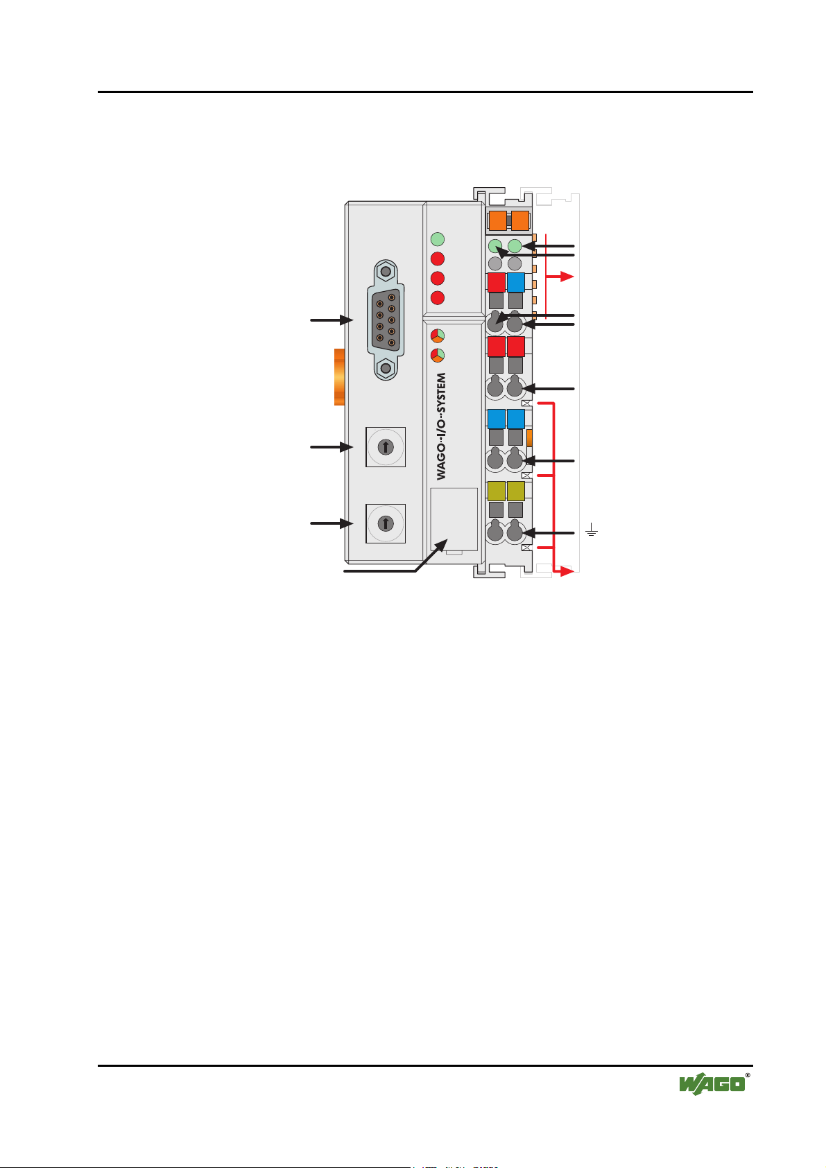
3.2.2 Hardware
3.2.2.1 View
Fieldbus coupler / controller • 77
Fieldbus Controller 750-833
Status der
Feldbusanschluss
D-Sub
PROFIBUS
RUN
BF
DIA
BUS
I/O
USR
01 02
A
B
0V
24V
++
Betriebsspannung
C
D
-Leistungskontakte
-System
Datenkontakte
Versorgung
24V
0V
Versorgung über
Leistungskontakte
24V
ADDRESS
--
0V
Adresse
x1
1
0
9
2
3
8
4
7
6
5
750-833
PE PE
Leistungskontakte
Adresse
Konfigurationsund Programmier-
8
0
9
7
6
x10
1
2
3
4
5
Schnittstelle
Fig. 3-12: Fieldbus coupler 750-833 PROFIBUS DP/V1 g083300d
The controller comprises of:
• Device supply with internal system supply module for the system supply as
well as power jumper contacts for the field supply via assembled I/O modules
• Fieldbus interface with the bus connection
• 2 rotary switches for the station address (decimal)
• Display elements (LED's) for status display of the operation, the bus com-
munication, the operating voltages as well as for fault messages and diagnosis
• Configuration and programming interface
• Operating mode switch
• Electronics for communication with the I/O modules (internal bus) and the
fieldbus interface
WAGO-I/O-SYSTEM 750 D R A F T
PROFIBUS 2001-02-27
Page 82

78 • Fieldbus coupler / controller
Fieldbus Controller 750-833
3.2.2.2 Device supply
The supply is via fed in via terminal blocks with CAGE CLAMP® connection.
Device supply is intended for system supply and field side supply.
1
5
24V/0V
10nF
DC
DC
Bus-
klemmen
0V
24V
2
6
24V
3
4
750-333
7
0V
8
NTERFACE
FELDBUS I
ELEKTRONIK
24V
0V
10nF
ELEKTRONIK
FELDBUS
INTERFACE
Fig. 3-13: Device supply g012105d
The integrated internal system supply module generates the necessary voltage
to supply the electronics and the connected I/O modules.
The fieldbus interface is supplied with electrically isolated voltage from the
internal system supply module.
D R A F T WAGO-I/O-SYSTEM 750
2001-02-27 PROFIBUS
Page 83

3.2.2.3 Fieldbus connection
The PROFIBUS interface is designed as a Sub-D connection in accordance
with the US Standard EIA RS 485 for cable linked data transmission.
9-pol. D-Sub-Buchse
9
VP
8
7
6
RxD/TxD-N
Fig. 3-14: Bus connection, D-SUB g012102d
Pin Signal Description
3 RxD(TxD)-P Transmit (receive) signal
5
DGND
4
RTS
3
RxD/TxD-P
2
1
Fieldbus coupler / controller • 79
Fieldbus Controller 750-833
4 RTS Ready To Send
5 GND Supply ground
6 Vcc Supply voltage
8 RxD(TxD) N Transmit (receive) signal
The connection point is mechanically lowered permitting fitting in an 80 mm
high switch box once connected
WAGO-I/O-SYSTEM 750 D R A F T
PROFIBUS 2001-02-27
Page 84

80 • Fieldbus coupler / controller
Fieldbus Controller 750-833
3.2.2.4 Display elements
The operating status of the fieldbus coupler or of the node is signalled via light
diodes (LED).
PROFIBUS
A
RUN
B
BF
DIA
BUS
24V
0V
C
D
I/O
USR
++
Fig. 3-15: Display elements 750-833 g012107x
LED Colour Meaning
RUN green The 'RUN' LED indicates to the user whether the fieldbus coupler /
controller is correctly initialised.
BF red The 'BF' LED indicates whether the communication via the
PROFIBUS is functioning.
DIA red The 'DIA' LED indicates an external diagnosis. The signalling is not
supported by all devices.
BUS red The 'BUS' LED signalled a projecting fault.
IO red /green
/ orange
USR red /green
/ orange
The 'I/O' LED indicates the operation of the node an and signals
faults occurring.
The 'USR' LED can be selected by a user program in a programmable fieldbus controller.
A green Status of the operating voltage – system
C green Status of the operating voltage – power jumper contact
D R A F T WAGO-I/O-SYSTEM 750
2001-02-27 PROFIBUS
Page 85

3.2.2.5 Station address
The station address is determined via two decimal rotary switches on the electronic module.
ADDRESS
x1
1
0
9
2
3
8
4
7
6
5
x10
1
0
9
2
3
8
4
7
6
5
Fig. 3-16: Creating the station address g012102d
The switch „x1“ determines the unit position of the address. The switch „x10“
determines the tens position of the address. Valid station addresses lie between
1 and 99.
Fieldbus coupler / controller • 81
Fieldbus Controller 750-833
The station address is taken over by the fieldbus coupler after switching on the
device (initialisation phase). Adjustments to the switch during operation have
no effect.
Note
After Power-On the station address 0 causes the run-up of the controller and
start of the PLC functions, without the fieldbus being active.
Using this function an autarcic small scale control can be realised using the
WAGO-I/O-SYSTEM 750
3.2.2.6 Configuration and programming interface
The configuration and programming interface is located behind the cover flap.
This is used to communicate with WAGO-I/O-CHECK and WAGO-I/O-PRO
as well as for firmware uploading.
Konfigurations- und
Programmierschnittstelle
Fig. 3-17: Configuration interface g01xx07d
The communication cable (750-920) is connected to the 4 pole male header.
WAGO-I/O-SYSTEM 750 D R A F T
PROFIBUS 2001-02-27
Page 86

82 • Fieldbus coupler / controller
Fieldbus Controller 750-833
3.2.2.7 Operating mode switch
The operating mode switch is located behind the cover flap.
Fig. 3-18: Operating mode switch g01xx10d
The switch is a push/slide switch with 3 settings and a hold-to-run function.
Operating mode switch Function
From middle to top position Activate program processing (RUN)
Betriebsartenschalter
From top to middle position Stop program processing (STOP)
(Lower position, bootstrap) (For original loading of firmware,
not necessary for user)
Push down
(e.g with a screwdriver)
Hardware reset
All outputs and flags are reset; variables are set to 0 or to
FALSE or to an initial value.
The hardware reset can be performed with STOP as well
as RUN in any position of the operating mode switch!
Attention
If outputs are set when switching over the operating mode switch from RUN
to STOP they remain set! Switching off on the software side e.g. by initiators,
are ineffective, because the program is no longer processed.
(An operating mode is internally changed at the end of a PLC cycle.)
Note
With "GET_STOP_VALUE" (library "System.lib") WAGO-I/O-PRO 32 provides a function which serves to recognise the last cycle prior to a program
stop giving the user the possibility to program the behaviour of the controller
in case of a STOP. With the aid of this function the controller outputs can be
switched to a safe condition.
D R A F T WAGO-I/O-SYSTEM 750
2001-02-27 PROFIBUS
Page 87

3.2.3 Operating system
3.2.3.1 Run-up
The controller runs-up after switching on the supply voltage or after a hardware reset. The PLC program in the flash memory is transferred to the RAM.
The "I/O" LED flashes orange.
The controller then checks all functions of its modules in a self test, the internal bus and the fieldbus interface. Following this the I/O modules and the present configuration is determined. At the same time a list is generated which is
not visible from outside. This includes an input and an output area, which
shows on the fieldbus RAM of the fieldbus RAM. This is followed by the initialisation of the system. The variables are set to 0 or to FALSE or to an initialisation value given by the PLC program. The flags retain their status . The
"I/O" LED blinks red during this phase.
Following a fault free run-up the controller changes over to the "Fieldbus start"
mode. The "I/O" LED lights up green.
Fieldbus coupler / controller • 83
Fieldbus Controller 750-833
A PLC program does not yet exist in the flash memory when delivered. The
controller runs-up as described, without initialising the system. It then behaves
as a coupler.
3.2.3.2 PLC cycle
The PLC cycle starts following a fault free run-up when the operating mode
switch is in the top position or by a start command from the WAGO-I/O-PRO
32. The input and output data of the fieldbus and the I/O modules as well as
the times are read. Subsequently the PLC program in the RAM is processed
followed by the output data of the fieldbus and the I/O modules in the process
image. Operating system functions, amongst others, for diagnosis and communication are performed an the times actualised at the end of the PLC cycle. The
cycle starts again with the reading in of the input and output data and the
times.
The change of the operating mode (STOP/RUN) is made at the end of a PLC
cycle.
The cycle time is the time from the start of the PLC program to the next start.
If a loop is programmed within a PLC program the PLC running time and thus
the PLC cycle are extended correspondingly.
The inputs, outputs and times are not updated during the processing of the
PLC program. This actualisation occurs in a defined manner only at the end of
the PLC program. For this reason it is not possible to wait for an event from
the process or the elapse of a time within a loop.
WAGO-I/O-SYSTEM 750 D R A F T
PROFIBUS 2001-02-27
Page 88

84 • Fieldbus coupler / controller
Fieldbus Controller 750-833
Versorgungsspannung
einschalten oder
Hardware-Reset
“I/O”-LED
blinkt
orange
“I/O”-LED
blinkt
rot
SPS-
Zyklus
SPS-Programm
im Flash-Speicher
Ja
SPS-Programm
vom Flash-Speicher
ins RAM übertragen
Controller-Selbsttest,
Ermittlung Busklemmen
und Konfiguration,
Erstellung interner Liste
Initialisierung des Systems
Fehler
Nein
Betriebsart
RUN
Ein-/Ausgänge u. Zeiten lesen
Ja
Nein
STOP
Controller-Selbsttest,
Ermittlung Busklemmen
und Konfiguration,
Erstellung interner Liste
Variablen auf 0 bzw. FALSE
oder auf Initialwert setzen,
Merker behalten ihren
Zustand bei
STOP
Betriebsartenschalter:
oberer Stellung oder
WAGO-I/O- 32:
‘Online’‘Start’/’Stop’
Feldbusdaten,
Busklemmendaten
Ja
PRO
Fehler
Nein
“I/O”-LED
grünan
Im RAM vorhandenes
SPS-Programm
bearbeiten
Ausgänge schreiben
Betriebssystem-Funktionen,
Zeiten aktualisieren
Betriebsart
RUN
STOP
Feldbusdaten,
Busklemmendaten
Betriebsartenschalter:
Stellungswechsel
WAGO-I/O- 32:
‘Online’‘Start’/’Stop’
PRO
Feldbusstart
Betrieb als Koppler
Fig. 3-19: Controller operating system g012112d
D R A F T WAGO-I/O-SYSTEM 750
2001-02-27 PROFIBUS
Page 89
3.2.4 Process image
3.2.4.1 Local process image
After switching on the controller recognises all I/O modules connected in the
node, which are waiting for or transmitting data (data width/bit width > 0). In
nodes analog and digital I/O modules can be fitted mixed.
Note
For the number of input and output bits or bytes of the individual switched on
I/O modules please refer to the corresponding description of the I/O modules.
The controller generates an internal local process image from the data width
and the type of I/O module as well as the position of the I/O modules in the
node. This is divided into an input and an output area.
The data of the digital I/O modules are bit orientated, i.e. the data exchange is
made bit by bit. The analog I/O modules are representative for all I/O modules
which are byte orientated, in which the data exchange is also made byte by
byte. These I/O modules also include, for example, counter modules, I/O modules for angle and path measurement as well as communication modules.
Fieldbus coupler / controller • 85
Fieldbus Controller 750-833
The data of the I/O modules is separated for the local input and output process
image in the sequence of their position after the controller in the individual
process image.
Note
If a node is changed or extended this may result in a new process image
structure. In this case the process data addresses also change in comparison
with earlier versions.
WAGO-I/O-SYSTEM 750 D R A F T
PROFIBUS 2001-02-27
Page 90
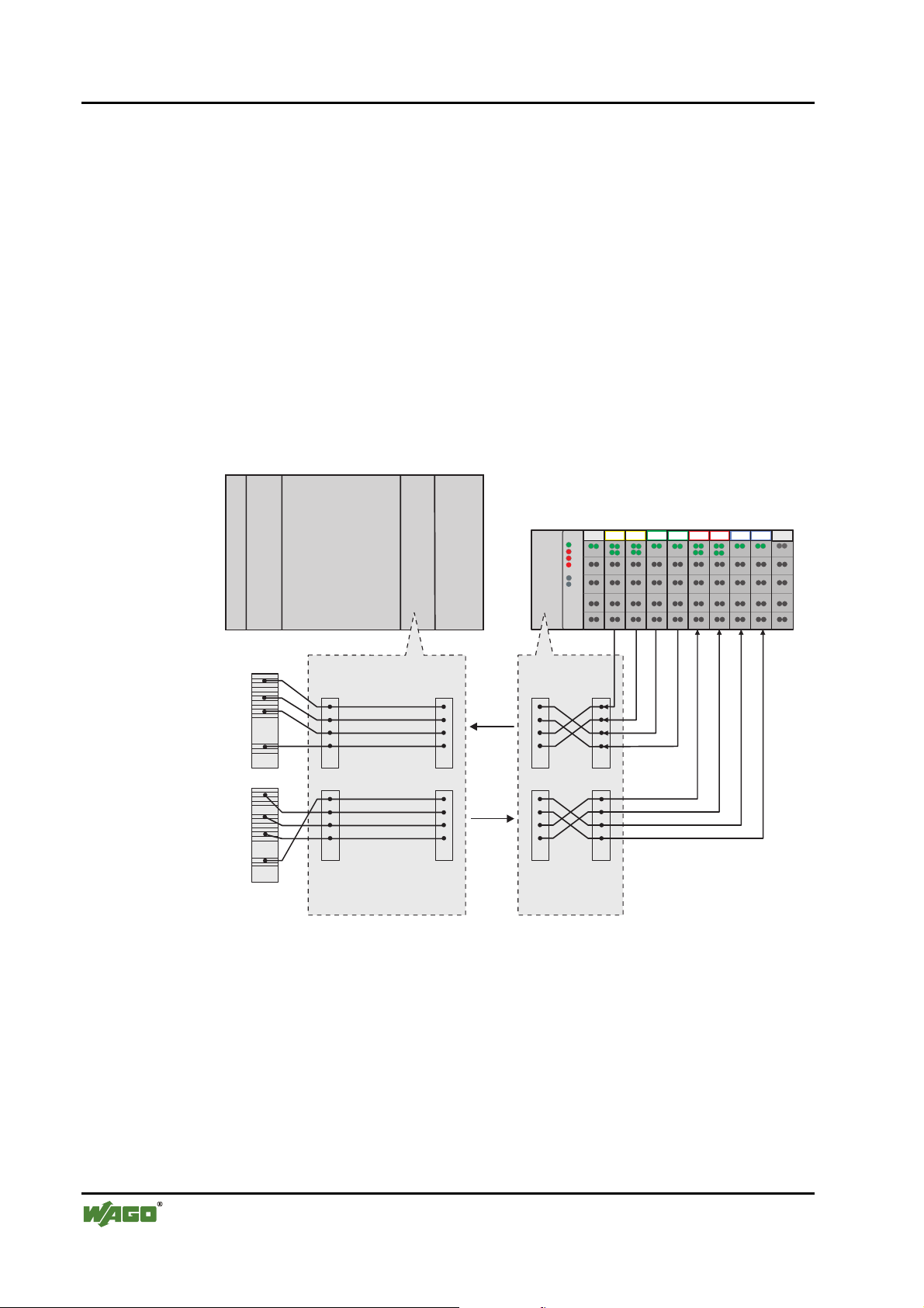
86 • Fieldbus coupler / controller
Fieldbus Controller 750-833
3.2.4.2 Allocation of the input and output data
The process data is exchanged via the PROFIBUS with the higher ranking
controls (Master). A maximum of 128 byte of data is transmitted from the
master to the controller, or node to the output data. The controller returns a
maximum of 128 byte input data as a reply to the master.
The modules are configured when projecting the nodes. These modules can be
copied from a hardware catalogue by the configurations programs. The information covering the possible modules is saved in the GSD files.
The controller generates an internal mapping in accordance with the installed
and configured settings of the node, in which the allocation of the input and
output data is determined in the local process image with the position in the
PROFIBUS DP Telegram.
Master, z. B. SPS
CPU
750-
1234 5 6789
DI
DOAOAO
AI
AI
DO
Anschaltung
452
504 504
550 550
600
Master-
Adressen
I
O
I
O
byteweise Zuordnung,
Erstellung aufdem PC
I
O
PROFIBUS
PROFIBUS
402DI402 452
ZuordnungslisteZuordnungsliste
II
OO
bit- und byteweise
Zuordnung,
Erstellung automatisch
durch den Koppler
Fig. 3-20: Allocation of the input and output data g012117d
D R A F T WAGO-I/O-SYSTEM 750
2001-02-27 PROFIBUS
Page 91

3.2.5 Configuration
The configuration of the node is performed in accordance with the physical requirements of the fieldbus controllers and I/O modules.
The fieldbus controller or the process data channel is to be configured on the
first slot.
The other slots are configured in accordance with the physical requirements of
the I/O modules, whereby only I/O modules with process data are relevant.
The supply modules without diagnosis, the supply modules without diagnosis,
the bus internal system supply module and the termination module are to be
ignored during configuration, as they do not provide any process data.
2 or 3 modules per I/O module are entered in the hardware catalogue. The
modules appear as
750-xyz ..., e.g. 750-400 2 DI/24 V DC/3.0 ms. and
PFC 750-xyz ..., e.g.. PFC 750-400 2 DI/24 V DC/3.0 ms.
The identification PFC 750-xyz ... states that the module concerned is exclusively processed by the internal control application. Its process data is not
transmitted via the PROFIBUS-DP to the master or to the higher ranking controls.
Fieldbus coupler / controller • 87
Fieldbus Controller 750-833
Alos the entry *750-xyz .... is listed for all binary modules. When using this
identification the controller adds the binary information of the current module
in a byte previously opened with 750-xyz .... The use of a „*“ module is only
permitted when the number of channels is less or identical to the remaining
bits in the previously opened byte. The binary I/O modules combined in a byte
may be at different locations, i.e. binary I/O modules of a different signal type
or byte orientated I/O modules can be connected between.
In order to configure the scope of the connected peripheries individually and
independent of the control program, it is possible to parameter the I/O modules
in the configuration table as „not plug fitted“. In this manner the process data
still on the PROFIBUS DP can be filtered for the individual module and not
transmitted to the periphery or read by it.
With the 750-833, after configuration of the connected periphery, the memory
area is configured due to the variable arrangement of the fieldbus variables.
For this the identification
1 byte PFC outputs, 2 byte PFC outputs to 64 byte PFC outputs
is available for the input image as well as
1 byte PFC inputs, 2 byte PFC inputs to 64 byte PFC inputs
for the output image.
By optionally combining the existing modules it is possible to project the required length on the fieldbus variables for PROFIBUS-DP.
WAGO-I/O-SYSTEM 750 D R A F T
PROFIBUS 2001-02-27
Page 92

88 • Fieldbus coupler / controller
Fieldbus Controller 750-833
3.2.5.1 GSD files
Under PROFIBUS DP the power features of the devices are defined by the
manufacturer in the form of a GSD file (device master data) and made available to the user.
Structure, content and coding of this device master data are standardised so
that projecting with any DP slaves with projecting data from various manufacturers is possible.
Further information
i
The PNO provides information about the GSD files of all listed manufacturers.
GSD and symbol files for the configuration of the I/O modules are available
under the order number 750-910 on disk or from the WAGO INTERNET
page.
http://www.wago.com
GSD file for I/O module 750-833 WAGOB756.GSD
The GSD file is read by the configuration software and the corresponding settings transferred. For the necessary entries and handling steps please refer to
the software user manuals.
D R A F T WAGO-I/O-SYSTEM 750
2001-02-27 PROFIBUS
Page 93

3.2.5.2 Identification bytes
The identification bytes contain information about the structure and the scope
of the inputs and outputs of the devices. For projecting each I/O module or
each channel is allocated an identification (module).
Bit Meaning
7 6 5 4 3 2 1 0
0
0
0
...
1
0
0
0
1
1
0
1
1
0
1
0
1
Fieldbus coupler / controller • 89
Fieldbus Controller 750-833
0
0
0
0
0
1
...
...
1
1
Data length
0
1 byte or word
1
2 bytes or words
0
3 bytes or words
...
...
1
16 bytes or 16 words
Input and output
Spec. identification formats
Input
Output
Input and output
Format
0 = Byte structure
1 = Word structure
Consistency about
Byte or word
Total length
For the special identification byte (Bit 4 and 5 = 00) is defined:
Bit Meaning
7 6 5 4 3 2 1 0
0
0
0
...
1
1
00
0
0
0
1
1
0
1
1
0
0
0
...
...
1
1
1
1
Length of the manufacturer specific data
0
0 = no manufacturer specific data
1
...
1 ... 14 = Length of the manufacturer specific data
0
1
15 = no manufacturer specific data follows
Input and output
Spec. identification formats
Input and output
unassigned slot
a length byte for inputs follows
a length byte for outputs follows
a length byte for inputs and outputs follows
Structure of the length byte:
Bit Meaning
7 6 5 4 3 2 1 0
0
0
0
0
...
...
1
0
1
0
1
...
1
1
1
...
...
1
1
Data length
0
1 byte or word
...
...
1
63 bytes or 63 words
Format
0 = Byte structur
1 = Word structur
Consistency about
Byte or word
Total length
WAGO-I/O-SYSTEM 750 D R A F T
PROFIBUS 2001-02-27
Page 94
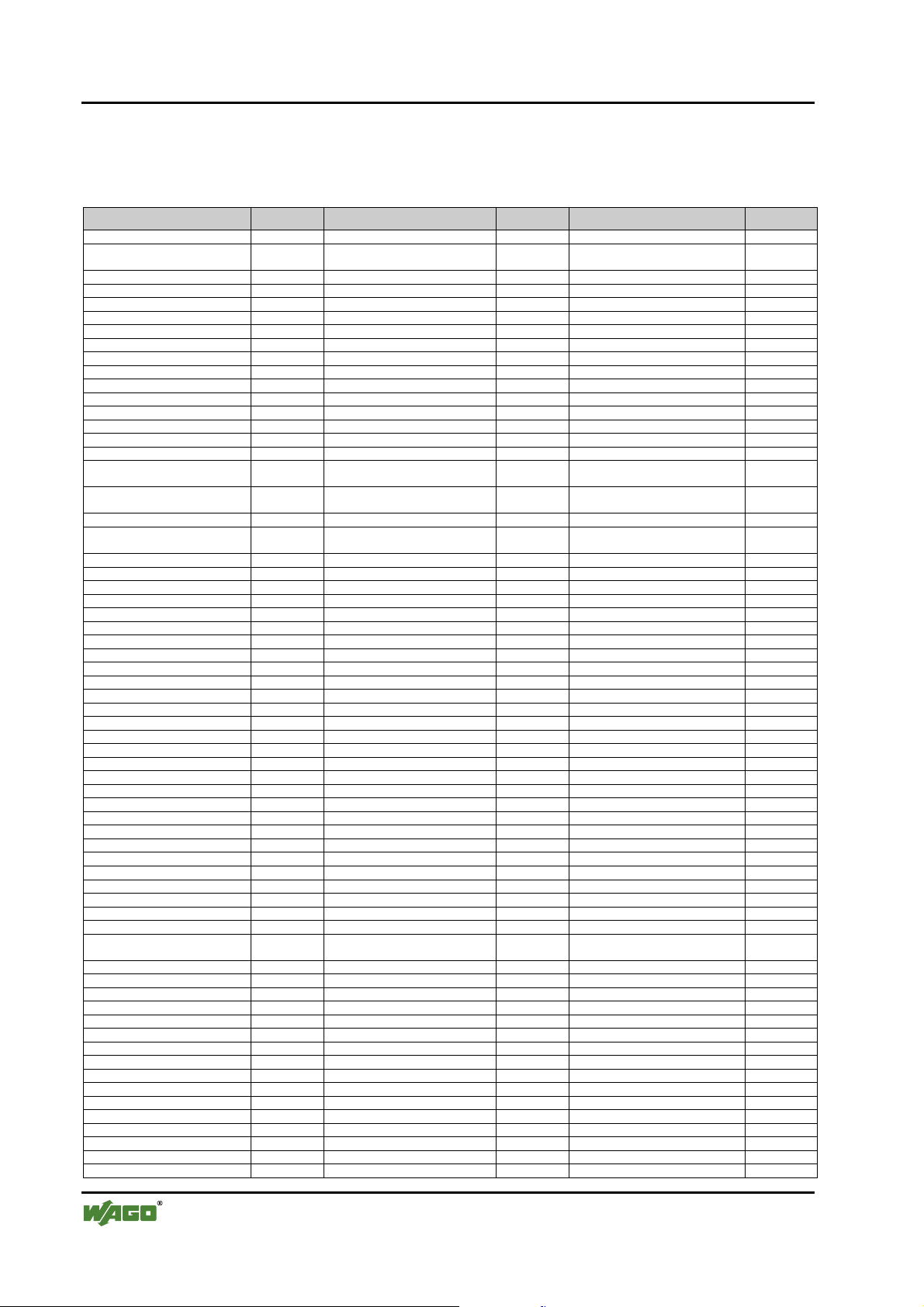
90 • Fieldbus coupler / controller
Fieldbus Controller 750-833
This information is saved in the GSD file. For projecting the I/O module is
selected in accordance with the article number using the configuration software contained in the hardware catalogue of the I/O module.
Module Ident. Module Ident. Module Ident.
750-833 No process data channel 0x00
750-833 2 byte process data
channel
750-400 2 DI/24 V DC/3.0 ms 0x10 *750-400 2 DI/24 V DC/3.0 ms 0x00 PFC 750-400 2 DI/24 V DC/3.0 ms 0x00
750-401 2 DI/24 V DC/0.2 ms 0x10 *750-401 2 DI/24 V DC/0.2 ms 0x00 PFC 750-401 2 DI/24 V DC/0.2 ms 0x00
750-402 4 DI/24 V DC/3.0 ms 0x10 *750-402 4 DI/24 V DC/3.0 ms 0x00 PFC 750-402 4 DI/24 V DC/3.0 ms 0x00
750-403 4 DI/24 V DC/0.2 ms 0x10 *750-403 4 DI/24 V DC/0.2 ms 0x00 PFC 750-403 4 DI/24 V DC/0.2 ms 0x00
750-404 Counter Module 0xF2 PFC 750-404 Counter Module 0x00
750-405 2 DI/230 V AC/10 ms 0x10 *750-405 2 DI/230 V AC/10 ms 0x00 PFC 750-405 2 DI/230 V AC/10 ms 0x00
750-406 2 DI/120 V AC/10 ms 0x10 *750-406 2 DI/120 V AC/10 ms 0x00 PFC 750-406 2 DI/120 V AC/10 ms 0x00
750-408 4 DI/24 V DC/3.0 ms 0x10 *750-408 4 DI/24 V DC/3.0 ms 0x00 PFC 750-408 4 DI/24 V DC/3.0 ms 0x00
750-409 4 DI/24 V DC/0.2 ms 0x10 *750-409 4 DI/24 V DC/0.2 ms 0x00 PFC 750-409 4 DI/24 V DC/0.2 ms 0x00
750-410 2 DI/24 V DC/3.0 ms 0x10 *750-410 2 DI/24 V DC/3.0 ms 0x00 PFC 750-410 2 DI/24 V DC/3.0 ms 0x00
750-411 2 DI/24 V DC/0.2 ms 0x10 *750-411 2 DI/24 V DC/0.2 ms 0x00 PFC 750-411 2 DI/24 V DC/0.2 ms 0x00
750-412 2 DI/48 V DC/3.0 ms 0x10 *750-412 2 DI/48 V DC/3.0 ms 0x00 PFC 750-412 2 DI/48 V DC/3.0 ms 0x00
750-413 2 DI/48 V DC/0.2 ms 0x10 *750-413 2 DI/48 V DC/0.2 ms 0x00 PFC 750-413 2 DI/48 V DC/0.2 ms 0x00
750-414 4 DI/5 V DC/0.2 ms 0x10 *750-414 4 DI/5 V DC/0.2 ms 0x00 PFC 750-414 4 DI/5 V DC/0.2 ms 0x00
750-415 4 DI/24 V AC/DC/20 ms 0x10 *750-415 4 DI/24 V AC/DC/20 ms 0x00 PFC 750-415 4 DI/24 V
750-418 2 DI/24 V DC DIA ACK 0x30 *750-418 2 DI/24 V DC DIA ACK 0x00 PFC 750-418 2 DI/24 V DC DIA
750-419 2 DI/24 V DC DIA 0x10 *750-419 2 DI/24 V DC DIA 0x00 PFC 750-419 2 DI/24 V DC DIA 0x00
750-423 4 DI/24 V AC/DC/50 ms 0x10 *750-423 4 DI/24 V AC/DC/50 ms 0x00 PFC 750-423 4 DI/24 V
750-424 2 DI/24 V DC DIA 0x10 *750-424 2 DI/24 V DC DIA 0x00 PFC 750-424 2 DI/24 V DC DIA 0x00
750-452 2 AI/0-20 mA/diff. 0x51 PFC 750-452 2 AI/0-20 mA/diff. 0x00
750-454 2 AI/4-20 mA/diff. 0x51 PFC 750-454 2 AI/4-20 mA/diff. 0x00
750-456 2 AI/±10 V/diff. 0x51 PFC 750-456 2 AI/±10 V/diff. 0x00
750-461 2 AI/RTD 0x51 PFC 750-461 2 AI/RTD 0x00
750-462 2 AI/TC 0x51 PFC 750-462 2 AI/TC 0x00
750-465 2 AI/0-20 mA/SE 0x51 PFC 750-465 2 AI/0-20 mA/SE 0x00
750-466 2 AI/4-20 mA/SE 0x51 PFC 750-466 2 AI/4-20 mA/SE 0x00
750-467 2 AI/0-10 V/SE 0x51 PFC 750-467 2 AI/0-10 V/SE 0x00
750-468 4 AI/0-10 V/SE 0x53 PFC 750-468 4 AI/0-10 V/SE 0x00
750-469 2 AI/TC/OCM 0x51 PFC 750-469 2 AI/TC/OCM 0x00
750-472 2 AI/0-20 mA/OVLP 0x51 PFC 750-472 2 AI/0-20 mA/OVLP 0x00
750-474 2 AI/4-20 mA/OVLP 0x51 PFC 750-474 2 AI/4-20 mA/OVLP 0x00
750-476 2 AI/±10 V 0x51 PFC 750-476 2 AI/±10 V 0x00
750-478 2 AI/0-10 V 0x51 PFC 750-478 2 AI/0-10 V 0x00
750-501 2 DO/24 V DC/0.5 A 0x20 *750-501 2 DO/24 V DC/0.5 A 0x00 PFC 750-501 2 DO/24 V DC/0.5 A 0x00
750-502 2 DO/24 V DC/2.0 A 0x20 *750-502 2 DO/24 V DC/2.0 A 0x00 PFC 750-502 2 DO/24 V DC/2.0 A 0x00
750-504 4 DO/24 V DC/0.5 A 0x20 *750-504 4 DO/24 V DC/0.5 A 0x00 PFC 750-504 4 DO/24 V DC/0.5 A 0x00
750-506 2 DO/24 V DC/0.5 A DIA 0x20 *750-506 2 DO/24 V DC/0.5 A DIA 0x00 PFC 750-506 2 DO/24 V DC/0.5 A 0x00
750-507 2 DO/24 V DC/2.0 A DIA 0x20 *750-507 2 DO/24 V DC/2.0 A DIA 0x00 PFC 750-507 2 DO/24 V DC/2.0 A 0x00
750-509 2 DO/230 V AC/0.3 A 0x20 *750-509 2 DO/230 V AC/0.3 A 0x00 PFC 750-509 2 DO/230 V AC/0.3 A 0x00
750-511 2 DO 24 V DC/PWM 0xF2 PFC 750-511 2 DO 24 V DC/PWM 0x00
750-512 2 DO Relay/250 V AC 0x20 *750-512 2 DO Relay/250 V AC 0x00 PFC 750-512 2 DO Relay/250 V AC 0x00
750-513 2 DO Relay/250 V AC 0x20 *750-513 2 DO Relay/250 V AC 0x00 PFC 750-513 2 DO Relay/250 V AC 0x00
750-514 2 DO Relay/125 V AC 0x20 *750-514 2 DO Relay/125 V AC 0x00 PFC 750-514 2 DO Relay/125 V AC 0x00
750-516 4 DO/24 V DC/0.5 A 0x20 *750-516 4 DO/24 V DC/0.5 A 0x00 PFC 750-516 4 DO/24 V DC/0.5 A 0x00
750-517 2 DO Relay/230 V AC 0x20 *750-517 2 DO Relay/230 V AC 0x00 PFC 750-517 2 DO Relay/230 V AC 0x00
750-519 4 DO/5 V DC/20 mA 0x20 *750-519 4 DO/5 V DC/20 mA 0x00 PFC 750-519 4 DO/5 V DC/20 mA 0x00
750-522 2 DO/230V AC/0.5 A
DIA
750-550 2 AO/0-10 V 0x61 PFC 750-550 2 AO/0-10 V 0x00
750-552 2 AO/0-20 mA 0x61 PFC 750-552 2 AO/0-20 mA 0x00
750-554 2 AO/4-20 mA 0x61 PFC 750-554 2 AO/4-20 mA 0x00
750-556 2 AO/±10 V 0x61 PFC 750-556 2 AO/±10 V 0x00
750-610 P supply. 24 V DC/DIA 0x00
750-611 P supply. 230 V AC/DIA 0x00
750-630 SSI-Intf. Standard 0x95 750-630 SSI-Intf. alternative 0x93 PFC 750-630 SS intf. 0x00
750-631 Encoder intf. 0xB5 PFC 750-631 Encoder intf. 0x00
750-650 RS232C-Intf. 5 Byte 0xB5 750-650 RS232C-Intf. 3 Byte 0xB3 PFC 750-650 RS232C intf. 0x00
750-651 TTY-Intf. 5 Byte 0xB5 750-651 TTY-Intf. 3 Byte 0xB3 PFC 750-651 TTY-Intf. 0x00
750-653 RS485-Intf. 5 Byte 0xB5 750-653 RS485 intf. 3 Byte 0xB3 PFC 750-653 RS485- intf. 0x00
750-654 Data exch. module 0xF1 PFC 750-654 Data exch. module 0x00
0xB1
0x20 *750-522 2 DO/230V AC/0.5 A
DIA
AC/DC/20ms
0x00
0x00
ACK
0x00
AC/DC/50ms
0x00 PFC 750-522 2 DO/230V DC/0.5 A 0x00
1 Byte PFC-input 0xA0 2 Byte PFC inputs 0xA1 3 Byte PFC inputs 0xA2
4 Byte PFC inputs 0xA3 5 Byte PFC inputs 0xA4 6 Byte PFC inputs 0xA5
7 Byte PFC inputs 0xA6 8 Byte PFC inputs 0xA7 9 Byte PFC inputs 0xA8
D R A F T WAGO-I/O-SYSTEM 750
2001-02-27 PROFIBUS
Page 95
Fieldbus coupler / controller • 91
Fieldbus Controller 750-833
Module Ident. Module Ident. Module Ident.
10 Byte PFC inputs 0xA9 11 Byte PFC inputs 0xAA 12 Byte PFC inputs 0xAB
13 Byte PFC inputs 0xAC 14 Byte PFC inputs 0xAD 15 Byte PFC inputs 0xAE
16 Byte PFC inputs 0xAF 17 Byte PFC inputs 0x80 , 0x90 18 Byte PFC inputs 0x80 , 0x91
19 Byte PFC inputs 0x80 , 0x92 20 Byte PFC inputs 0x80 , 0x93 21 Byte PFC inputs 0x80 , 0x94
22 Byte PFC inputs 0x80 , 0x95 23 Byte PFC inputs 0x80 , 0x96 24 Byte PFC inputs 0x80 , 0x97
25 Byte PFC inputs 0x80 , 0x98 26 Byte PFC inputs 0x80 , 0x99 27 Byte PFC inputs 0x80 , 0x9A
28 Byte PFC inputs 0x80 , 0x9B 29 Byte PFC inputs 0x80 , 0x9C 30 Byte PFC inputs 0x80 , 0x9D
31 Byte PFC inputs 0x80 , 0x9E 32 byte PFC inputs 0x80 , 0x9F 33 Byte PFC inputs 0x80 , 0xA0
34 Byte PFC inputs 0x80 , 0xA1 35 Byte PFC inputs 0x80 , 0xA2 36 Byte PFC inputs 0x80 , 0xA3
37 Byte PFC inputs 0x80 , 0xA4 38 Byte PFC inputs 0x80 , 0xA5 39 Byte PFC inputs 0x80 , 0xA6
40 Byte PFC inputs 0x80 , 0xA7 41 Byte PFC inputs 0x80 , 0xA8 42 Byte PFC inputs 0x80 , 0xA9
43 Byte PFC inputs 0x80 , 0xAA 44 Byte PFC inputs 0x80 , 0xAB 45 Byte PFC inputs 0x80 , 0xAC
46 Byte PFC inputs 0x80 , 0xAD 47 Byte PFC inputs 0x80 , 0xAE 48 Byte PFC inputs 0x80 , 0xAF
49 Byte PFC inputs 0x80 , 0xB0 50 Byte PFC inputs 0x80 , 0xB1 51 Byte PFC inputs 0x80 , 0xB2
52 Byte PFC inputs 0x80 , 0xB3 53 Byte PFC inputs 0x80 , 0xB4 54 Byte PFC inputs 0x80 , 0xB5
55 Byte PFC inputs 0x80 , 0xB6 56 Byte PFC inputs 0x80 , 0xB7 57 Byte PFC inputs 0x80 , 0xB8
58 Byte PFC inputs 0x80 , 0xB9 59 Byte PFC inputs 0x80 , 0xBA 60 Byte PFC inputs 0x80 , 0xBB
61 Byte PFC inputs 0x80 , 0xBC 62 Byte PFC inputs 0x80 , 0xBD 63 Byte PFC inputs 0x80 , 0xBE
64 Byte PFC inputs 0x80 , 0xBF
1 Byte PFC outputs 0x90 2 Byte PFC outputs 0x91 3 Byte PFC outputs 0x92
4 Byte PFC outputs 0x93 5 Byte PFC outputs 0x94 6 Byte PFC outputs 0x95
7 Byte PFC outputs 0x96 8 Byte PFC outputs 0x97 9 Byte PFC outputs 0x98
10 Byte PFC outputs 0x99 11 Byte PFC outputs 0x9A 12 Byte PFC outputs 0x9B
13 Byte PFC outputs 0x9C 14 Byte PFC outputs 0x9D 15 Byte PFC outputs 0x9E
16 Byte PFC outputs 0x9F 17 Byte PFC outputs 0x40 , 0x90 18 Byte PFC outputs 0x40 , 0x91
19 Byte PFC outputs 0x40 , 0x92 20 Byte PFC outputs 0x40 , 0x93 21 Byte PFC outputs 0x40 , 0x94
22 Byte PFC outputs 0x40 , 0x95 23 Byte PFC outputs 0x40 , 0x96 24 Byte PFC outputs 0x40 , 0x97
25 Byte PFC outputs 0x40 , 0x98 26 Byte PFC outputs 0x40 , 0x99 27 Byte PFC outputs 0x40 , 0x9A
28 Byte PFC outputs 0x40 , 0x9B 29 Byte PFC outputs 0x40 , 0x9C 30 Byte PFC outputs 0x40 , 0x9D
31 Byte PFC outputs 0x40 , 0x9E 32 Byte PFC outputs 0x40 , 0x9F 33 Byte PFC outputs 0x40 , 0xA0
34 Byte PFC outputs 0x40 , 0xA1 35 Byte PFC outputs 0x40 , 0xA2 36 Byte PFC outputs 0x40 , 0xA3
37 Byte PFC outputs 0x40 , 0xA4 38 Byte PFC outputs 0x40 , 0xA5 39 Byte PFC outputs 0x40 , 0xA6
40 Byte PFC outputs 0x40 , 0xA7 41 Byte PFC outputs 0x40 , 0xA8 42 Byte PFC outputs 0x40 , 0xA9
43 Byte PFC outputs 0x40 , 0xAA 44 Byte PFC outputs 0x40 , 0xAB 45 Byte PFC outputs 0x40 , 0xAC
46 Byte PFC outputs 0x40 , 0xAD 47 Byte PFC outputs 0x40 , 0xAE 48 Byte PFC outputs 0x40 , 0xAF
49 Byte PFC outputs 0x40 , 0xB0 50 Byte PFC outputs 0x40 , 0xB1 51 Byte PFC outputs 0x40 , 0xB2
52 Byte PFC outputs 0x40 , 0xB3 53 Byte PFC outputs 0x40 , 0xB4 54 Byte PFC outputs 0x40 , 0xB5
55 Byte PFC outputs 0x40 , 0xB6 56 Byte PFC outputs 0x40 , 0xB7 57 Byte PFC outputs 0x40 , 0xB8
58 Byte PFC outputs 0x40 , 0xB9 59 Byte PFC outputs 0x40 , 0xBA 60 Byte PFC outputs 0x40 , 0xBB
61 Byte PFC outputs 0x40 , 0xBC 62 Byte PFC outputs 0x40 , 0xBD 63 Byte PFC outputs 0x40 , 0xBE
64 Byte PFC outputs 0x40 , 0xBF
WAGO-I/O-SYSTEM 750 D R A F T
PROFIBUS 2001-02-27
Page 96

92 • Fieldbus coupler / controller
Fieldbus Controller 750-833
3.2.5.3 Example
A fieldbus node with a controller and 17 I/O modules should make the arrangement clear.
1234 5 67891011121314151617
DI DI
750-333
402
Fig. 3-21: Example application g012115x
DI DI
402 402
DI DI
AI AI
452
DO DODO DO
602 504
DO DO DO DODO DO
504 504504
DO DO
504
602
AO AO
AI AI
AO AO AI AI DO DO
452
452
602
504
600550 550
PROFIBUS
I/O modules PI Master *No. Modul
Identification
1
2
3
5 Potential supply Potential supply --- ---
6
7
Digital input 750-402 4 DI/24 V DC/3.0 ms EB12.0
Digital input 0x10 EB12.1
Digital input EB12.2
Digital input EB12.3
Digital input *750-402 4 DI/24 V DC/3.0 ms EB12.4
Digital input 0x00 EB12.5
Digital input EB12.6
Digital input EB12.7
Digital input 750-402 4 DI/24 V DC/3.0 ms EB13.0
Digital input 0x10 EB13.1
Digital input EB13.2
Digital input EB13.3
Analog input 750-452 2 AI/0-20 mA/diff. EW04
Analog input 0x51 EW2
Digital output 750-504 4 DO/24 V DC/0.5 A AB8.0
Digital output 0x20 AB8.1
Digital output AB8.2
Digital output AB8.3
Digital output *750-504 4 DO/24 V DC/0.5 A AB8.4
Digital output 0x00 AB8.5
Digital output AB8.6
Digital output AB8.7
Inputs Outputs
D R A F T WAGO-I/O-SYSTEM 750
2001-02-27 PROFIBUS
Page 97

Fieldbus coupler / controller • 93
Fieldbus Controller 750-833
8
9
10 Potential supply Potential supply --- ---
15 Potential supply Potential supply --- ---
16
17 End module End module --- ---
Digital output 750-504 4 DO/24 V DC/0.5 A AB9.0
Digital output 0x20 AB9.1
Digital output AB9.2
Digital output AB9.3
Digital output *750-504 4 DO/24 V DC/0.5 A AB9.4
Digital output 0x00 AB9.5
Digital output AB9.6
Digital output AB9.7
Analog output 750-550 2 AO/0-10 V AW011
Analog output 0x61 AW2
Analog input 750-452 2 AI/0-20 mA/diff. EW412
Analog input 0x51 EW6
Analog output 750-550 2 AO/0-10 V AW413
Analog output 0x61 AW6
Analog input 750-452 2 AI/0-20 mA/diff. EW814
Analog input 0x51 EW10
Digital output 750-504 4 DO/24 V DC/0.5 A AB10.0
Digital output 0x20 AB10.1
Digital output AB10.2
Digital output AB10.3
* The master addresses listed in the table correspond to the allocation of the process data
given in the master configuration.
WAGO-I/O-SYSTEM 750 D R A F T
PROFIBUS 2001-02-27
Page 98

94 • Fieldbus coupler / controller
Fieldbus Controller 750-833
3.2.6 Parameterisation of the controllers
Before a data exchange can be performed between master and slave, a parameterisation is required in addition to configuration.
The extended parameters (Extended User_Prm_Data) are provided via the
GSD files as selectable text in the configuration programs.
Description Value Meaning
Restart the internal bus after a
fault
I/O module diagnosis The diagnosis information of all I/O modules
Process value display Word or double word oriented process data, is
Behaviour in case of a
PROFIBUS DP fault
POWER ON RESET
AUTORESET immediately after overcoming the internal bus
*)
released
locked not transferred to PROFIBUS-DP master
INTEL „Little Endian Format“
MOTOROLA
Stop internal bus transmission
Set output image to zero all outputs are immediately reset
Freeze output image all outputs maintain the last status before the
Write substitute value
PFC fault strategy PFC takes over the control via the output image
*)
*)
Restart of the terminal bus following a fault,
such as, for example, no termination module
following an interruption of the supply
fault
with a diagnosis capability, for which the
diagnosis is released are
transferred to PROFIBUS-DP master,
transferred to PROFIBUS-DP master in:
„Big Endian Format“
In the case of a malfunction of the
PROFIBUS DP communication the status of the
connected output periphery can be influenced in
various ways:
The process data exchange on the internal bus is
stopped, all outputs drop out after a module
specific monitoring time of 100 ms
malfunction
*)
all outputs switch a parameterisable substitute
value
Reaction to an internal bus fault In the event of a malfunction of an internal
Stop PROFIBUS data
exchange
Set input image to zero the input information is set to zero
Freeze input image the input information prevailing before the fault
*)
*)
Default settings
communication between fieldbus controller and
I/O modules, such as, for example no termination module,
the data exchange with the PROFIBUS master
is stopped.
is maintained
D R A F T WAGO-I/O-SYSTEM 750
2001-02-27 PROFIBUS
Page 99

Fieldbus coupler / controller • 95
Fieldbus Controller 750-833
The complete data block encompasses 34 parameterised bytes. The first 10
bytes are laid down via the DP and DPV1 standard. The others receive manufacturer specific parameters.
Byte No. Bit No. Value Meaning
Standard parameters
0 0-7 Station status (see EN 50170)
1 0-7 2-255 Watchdog factor 1
2 0-7 2-255 Watchdog factor 2
3 0-7 11-255 Min T
4 0-7 183, 0xB7 Manufacturer Identification (high byte)
5 0-7 86, 0x56 Manufacturer Identification (low byte)
6 0-7 Group membership,
7 0-7 DPV1 status 1 (see EN 50170)
8 0-7 DPV1 status 2 (see EN 50170)
9 0-7 DPV1 status 3 (see EN 50170)
Manufacturer parameters
10 0-7 0 Table 0, register 0 LB, reserved
11 0-7 0 Table 0, register 0 HB, reserved
12 0-7 0 Table 0, register 1 LB, reserved
13 0-7 0 Table 0, register 1 HB, reserved
14 Table 0, register 2 LB
15 0-7 0 Table 0, register 2 HB, reserved
16 Table 0, register 3 LB
17 Table 0, register 3 HB
18 0-7 '1100.0011' Table 0, register 4 LB, reserved
19 0-7 '0111.1111' Table 0, register 4 HB, reserved
20 0-7 '0000.0000' Table 100, register 0 LB, reserved
21 0-7 '0000.0001' Table 100, register 0 HB, reserved
22 0-7 '0000.0000' Table 100, register 1 LB, reserved
23 0-7 '0000.0000' Table 100, register 1 HB, reserved
24 0-7 '0000.0000' Table 100, register 2 LB, reserved
25 0-7 '0000.0000' Table 100, register 2 HB, reserved
0 0 Device diagnosis locked
01*)Device diagnosis released
1 0 Internal bus restart after fault: POWER-ON-RESET
11*)Internal bus restart after fault: AUTORESET
2-7 0 reserved
0-2 '011' reserved
3 0 Data format byte orientated I/O modules: INTEL
31*)Data format byte orientated I/O modules: MOTOROLA
4-7 '1100' reserved
0-2 Reaction to fieldbus fault:
3-5 Reaction to internal bus fault:
6-7 '00' reserved
'000'
'001'
'010'
'011'
'100'
'101'
'110'
'111'
'000'
'001'
'010'
'011'
'100'
'101'
'110'
'111'
*)
*)
Watchdog:
The response monitoring is the result of
Watchdog_Factor_1 x Watchdog_Factor_2 x 10 ms (1 ms)
Earliest time in T
Broad and multicast telegrams (SYNC, FREEZE)
- Stop internal bus transmission
- Set output image to zero
- Freeze output image
- Write substitute values
- PFC fault strategy
- Not possible
- Not possible
- Not possible
- Exit data exchange
- Set input image to zero
- Freeze input image
- Not possible
- Not possible
- Not possible
- Not possible
- Not possible
SDR
,
after which the slave can reply
Bit
WAGO-I/O-SYSTEM 750 D R A F T
PROFIBUS 2001-02-27
Page 100
96 • Fieldbus coupler / controller
Fieldbus Controller 750-833
3.2.7 Configuration of the process data channels
The process data channels serve the communication between the WAGO-I/OPRO and the running time system of the fieldbus controller. If this channel is
not required it can be projected with a process data length of zero
(750-833 No process data channel).
Module Identification
750-833 no process data channel
750-833 2 byte process data channel
hex
0x00
0xB1
Note
Configure the module 750-833 2 byte process data channel or
750-833 No process data channel as 1
st
module.
Identification
dec
0
177
D R A F T WAGO-I/O-SYSTEM 750
2001-02-27 PROFIBUS
 Loading...