

Page 1
Modular I/O System
DeviceNet
750-306, 750-806
Manual
Technical Description,
Installation and
Configuration
Supplement for the Manual 750-135
Version 2002-07-01
Page 2

ii • General
Copyright ã 2002 by WAGO Kontakttechnik GmbH
All rights reserved.
WAGO Kontakttechnik GmbH
Hansastraße 27
D-32423 Minden
Phone: +49 (0) 571/8 87 – 0
Fax: +49 (0) 571/8 87 – 1 69
E-Mail: info@wago.com
Web: http://www.wago.com
Technical Support
Phone: +49 (0) 571/8 87 – 5 55
Fax: +49 (0) 571/8 87 – 85 55
E-Mail: support@wago.com
Every conceivable measure has been taken to ensure the correctness and completeness of this documentation. However, as errors can never be fully excluded we would appreciate any information or ideas at any time.
E-Mail: documentation@wago.com
We wish to point out that the software and hardware terms as well as the
trademarks of companies used and/or mentioned in the present manual are
generally trademark or patent protected.
WAGO-I/O-SYSTEM 750
DeviceNet
Page 3

TABLE OF CONTENTS
1 Important Comments.................................................................................4
1.1 Legal Principles......................................................................................4
1.2 Symbols..................................................................................................5
1.3 Font Conventions ...................................................................................6
1.4 Number Notation....................................................................................6
1.5 Safety Notes ...........................................................................................7
1.6 Scope ......................................................................................................8
1.7 Abbreviation...........................................................................................8
2 The WAGO-I/O-SYSTEM 750 .................................................................9
2.1 System Description ................................................................................9
2.2 Technical Data......................................................................................10
2.3 Manufacturing Number........................................................................13
2.4 Storage, Consignment and Transport...................................................14
2.5 Mechanical Setup .................................................................................14
2.6 Power Supply .......................................................................................22
2.7 Grounding.............................................................................................33
2.8 Shielding (screening)............................................................................36
2.9 Assembly Guidelines / Norms .............................................................37
Table of Contents • iii
3 Fieldbus Coupler/Controller...................................................................38
3.1 Fieldbus Coupler 750-306....................................................................38
3.2 Fieldbus Controller 750-806 ................................................................61
4 I/O modules.............................................................................................105
5 DeviceNet.................................................................................................106
5.1 Description .........................................................................................106
5.2 Network Architecture.........................................................................107
5.3 Network Communication ...................................................................112
5.4 Module Characteristics.......................................................................113
5.5 Process data and Diagnostic Status ....................................................114
5.6 Configuration / Parametering with the Object Model........................116
6 Application in Explosive Environments...............................................139
6.1 Foreword ............................................................................................139
6.2 Protective Measures ...........................................................................139
6.3 Classification Meeting CENELEC and IEC ......................................139
6.4 Classifications Meeting the NEC 500 ................................................144
6.5 Identification ......................................................................................146
6.6 Installation Regulations......................................................................148
7 Glossary...................................................................................................150
8 Literature List ........................................................................................151
9 Index ........................................................................................................152
WAGO-I/O-SYSTEM 750
DeviceNet
Page 4

4 • Important Comments
Legal Principles
1 Important Comments
To ensure fast installation and start-up of the units described in this manual,
we strongly recommend that the following information and explanations are
carefully read and abided by.
1.1 Legal Principles
1.1.1 Copyright
This manual is copyrighted, together with all figures and illustrations contained therein. Any use of this manual which infringes the copyright provisions stipulated herein, is not permitted. Reproduction, translation and electronic and photo-technical archiving and amendments require the written consent of WAGO Kontakttechnik GmbH. Non-observance will entail the right of
claims for damages.
WAGO Kontakttechnik GmbH reserves the right to perform modifications
allowed by technical progress. In case of grant of a patent or legal protection
of utility patents all rights are reserved by WAGO Kontakttechnik GmbH.
Products of other manufacturers are always named without referring to patent
rights. The existence of such rights can therefore not be ruled out.
1.1.2 Personnel Qualification
The use of the product detailed in this manual is exclusively geared to specialists having qualifications in PLC programming, electrical specialists or
persons instructed by electrical specialists who are also familiar with the valid
standards. WAGO Kontakttechnik GmbH declines all liability resulting from
improper action and damage to WAGO products and third party products due
to non-observance of the information contained in this manual.
1.1.3 Intended Use
For each individual application, the components supplied are to work with a
dedicated hardware and software configuration. Modifications are only permitted within the framework of the possibilities documented in the manuals.
All other changes to the hardware and/or software and the non-conforming use
of the components entail the exclusion of liability on part of WAGO Kontakttechnik GmbH.
Please direct any requirements pertaining to a modified and/or new hardware
or software configuration directly to WAGO Kontakttechnik GmbH.
WAGO-I/O-SYSTEM 750
DeviceNet
Page 5
1.2 Symbols
Important Comments • 5
Symbols
Danger
Always abide by this information to protect persons from injury.
Warning
Always abide by this information to prevent damage to the device.
Attention
Marginal conditions must always be observed to ensure smooth operation.
ESD (Electrostatic Discharge)
Warning of damage to the components by electrostatic discharge. Observe the
precautionary measure for handling components at risk.
Note
Routines or advice for efficient use of the device and software optimization.
More information
References on additional literature, manuals, data sheets and INTERNET
pages
WAGO-I/O-SYSTEM 750
DeviceNet
Page 6

6 • Important Comments
Font Conventions
1.3 Font Conventions
Italic
Italic
\
END
< >
Courier Program code is printed with the font Courier.
1.4 Number Notation
Names of path and files are marked italic
i.e.: C:\programs\WAGO-IO-CHECK
Menu items are marked as bold italic
i.e.: Save
A backslash between two names marks a sequence of
menu items
i.e.: File\New
Press buttons are marked as bold with small capitals
i.e.: ENTER
Keys are marked bold within angle brackets
i.e.: <F5>
i.e.: END_VAR
Number Code Example Note
Decimal 100 normal notation
Hexadecimal 0x64 C notation
Binary '100'
'0110.0100'
Within ',
Nibble separated with dots
WAGO-I/O-SYSTEM 750
DeviceNet
Page 7
1.5 Safety Notes
Attention
Switch off the system prior to working on bus modules!
In the event of deformed contacts, the module in question is to be replaced, as
its functionality can no longer be ensured on a long-term basis.
The components are not resistant against materials having seeping and insulating properties. Belonging to this group of materials is: e.g. aerosols, silicones, triglycerides (found in some hand creams).
If it cannot be ruled out that these materials appear in the component environment, then additional measures are to be taken:
- installation of the components into an appropriate housing
- handling of the components only with clean tools and materials.
Attention
Cleaning of soiled contacts may only be done with ethyl alcohol and leather
cloths. Thereby, the ESD information is to be regarded.
Important Comments • 7
Safety Notes
Do not use any contact spray, as in a worst-case scenario; the functioning of
the contact area can be impaired.
The WAGO-I/O-SYSTEM 750 and its components are an open system. It
must only be assembled in housings, cabinets or in electrical operation
rooms. Access must only be given via a key or tool to authorized qualified
personnel.
The relevant valid and applicable standards and guidelines concerning the
installation of switch boxes are to be observed.
ESD (Electrostatic Discharge)
The modules are equipped with electronic components that may be destroyed
by electrostatic discharge. When handling the modules, ensure that the environment (persons, workplace and packing) is well grounded. Avoid touching
conductive components, e.g. gold contacts.
WAGO-I/O-SYSTEM 750
DeviceNet
Page 8
8 • Important Comments
Scope
1.6 Scope
Item no. Description
750-306 fieldbus Coupler DeviceNet; 125 – 500 kBaud
750-806 prog. Fieldbus Controller DeviceNet; 125 – 500 kBaud
Attention
This document is a supplement for the DeviceNet manual.
This manual describes the modular WAGO-I/O-SYSTEM 750 with the fieldbus Coupler for DeviceNet or with the programmable fieldbus Controller for
DeviceNet.
This extract does not contain:
The chapter 3 "I/O modules"
(Description of the field bus independent I/O modules).
1.7 Abbreviation
AI
AO
BC
CAL
CAN
DI
DIP
DO
EDS
I/O
ID
Idx
ISO/ OSI
M
MAC ID
MS
Analog Input
Analog Output
BusCoupler
CAN Application Layer
Controller Area Network
Digital Input
Dual In-line Package
Digital Output
Electronic Data Sheets
Input/Output
Identifier, Identification
Index
International Organization for Standardization / Open Systems Interconnection (model)
Master
Media Access Control Identifier (nodeaddress)
Module Status
NMT
NS
PFC
RO
RW
Network Management
Network Status
Programmable fieldbus Controller
Read Only
Read/Write
WAGO-I/O-SYSTEM 750
DeviceNet
Page 9
2 The WAGO-I/O-SYSTEM 750
2.1 System Description
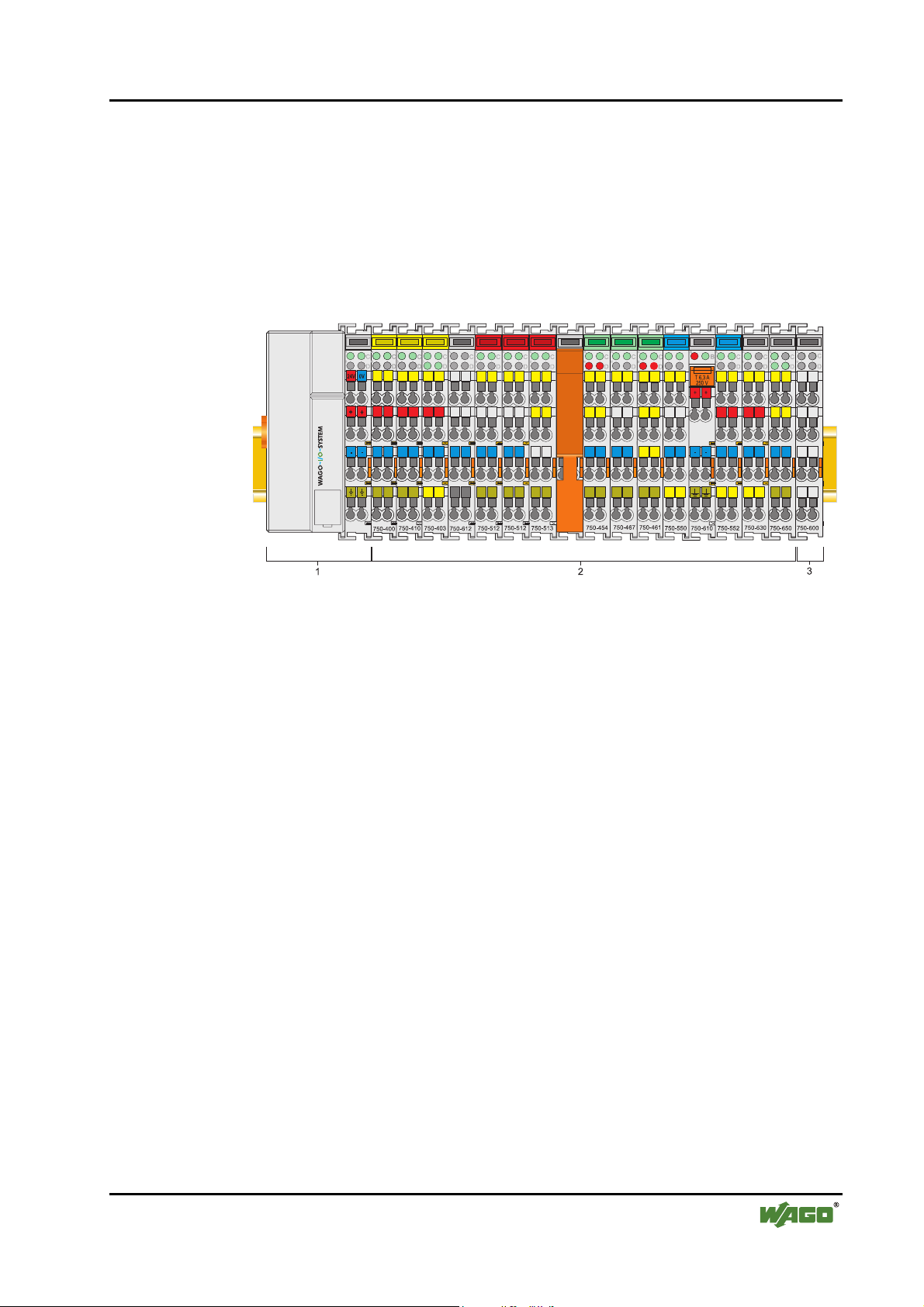
The WAGO-I/O-SYSTEM 750 is a modular, fieldbus independent I/O system.
It is comprised of a fieldbus coupler/controller (1) and up to 64 connected
fieldbus modules (2) for any kind of signal. Together, these make up the
fieldbus node. The end module (3) completes the node.
The WAGO-I/O-SYSTEM 750 • 9
System Description
Fig. 2-1: Fieldbus node g0xxx00x
Couplers / controllers for fieldbus systems such as PROFIBUS, INTERBUS,
ETHERNET TCP/IP, CAN (CANopen, DeviceNet, CAL), MODBUS, LON
and others are available.
The coupler / controller contains the fieldbus interface, electronics and a
power supply terminal. The fieldbus interface forms the physical interface to
the relevant fieldbus. The electronics process the data of the bus modules and
make it available for the fieldbus communication. The 24 V system supply and
the 24 V field supply are fed in via the integrated power supply terminal.
The fieldbus coupler communicates via the relevant fieldbus. The programmable fieldbus controller (PFC) enables the implementation of additional PLC
functions. Programming is done with the WAGO-I/O-PRO 32 in accordance
with IEC 61131-3.
Bus modules for diverse digital and analogue I/O functions as well as special
functions can be connected to the coupler / controller. The communication
between the coupler/controller and the bus modules is carried out via an internal bus.
The WAGO-I/O-SYSTEM 750 has a clear port level with LEDs for the status
indication, insertable mini WSB markers and pullout group marker carriers.
The 3-wire technology supplemented by a ground wire connection allows the
direct sensor/actuator wiring.
WAGO-I/O-SYSTEM 750
DeviceNet
Page 10
10 • The WAGO-I/O-SYSTEM 750
Technical Data
2.2 Technical Data
Mechanic
Material Polycarbonate, Polyamide 6.6
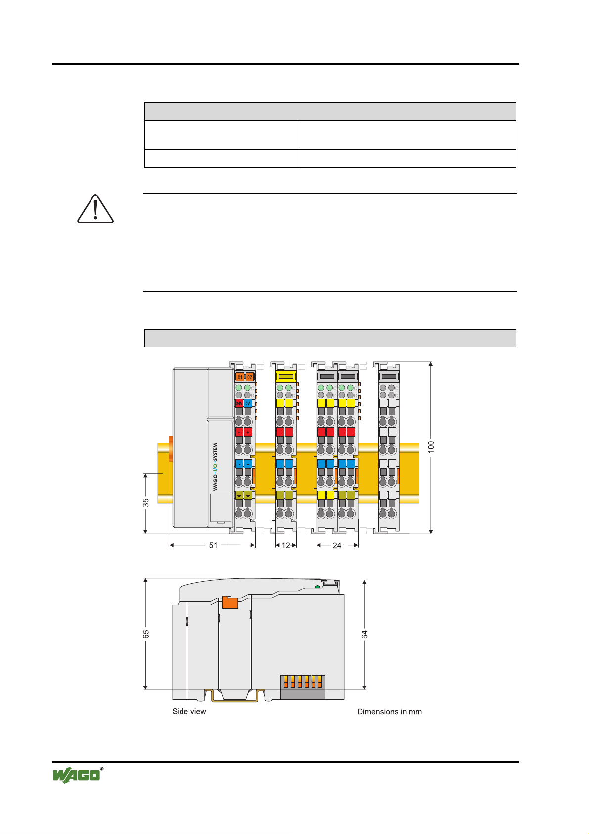
Dimensions Coupler / Controller 51 mm x 65* mm x 100 mm
Dimensions I/O module, single 12 mm x 64* mm x 100 mm
Dimensions I/O module, double 24 mm x 64* mm x 100 mm
Installation on DIN 35 with interlock
modular by double featherkey-dovetail
Mounting position any position
Length of entire node
≤ 831 mm
Marking marking label type 247 and 248
paper marking label 8 x 47 mm
Wire range
Wire range CAGE CLAMP® Connection
0,08 mm² ... 2.5 mm²
AWG 28-14
8 – 9 mm Stripped length
Contacts
Power jumpers contacts blade/spring contact
self-cleaning
Current via power contacts
Voltage drop at I
max
max
10 A
< 1 V/64 modules
Data contacts slide contact, hard gold plated
1,5µ, self-cleaning
Climatic environmental conditions
Operating temperature 0 °C ... 55 °C
Storage temperature -20 °C ... +85 °C
Relative humidity 95 % without condensation
Resistance to harmful substances acc. to IEC 60068-2-42 and IEC 60068-2-43
Special conditions Ensure that additional measures for components are
taken, which are used in an environment involving:
– dust, caustic vapors or gasses
– ionization radiation.
Mechanical strength
Vibration resistance acc. to IEC 60068-2-6
Shock resistance acc. to IEC 60068-2-27
Free fall acc. to IEC 60068-2-32
≤ 1m (module in original packing)
* from upper edge of DIN 35 rail
WAGO-I/O-SYSTEM 750
DeviceNet
Page 11
The WAGO-I/O-SYSTEM 750 • 11
Safe electrical isolation
Air and creepage distance acc. to IEC 60664-1
Degree of protection
Degree of protection IP 20
Electromagnetic compatibility*
Technical Data
Directive Test values Strength
class
Immunity to interference acc. to EN 50082-2 (96)
EN 61000-4-2 4kV/8kV (2/4) B
EN 61000-4-3 10V/m 80% AM (3) A
EN 61000-4-4 2kV (3/4) B
EN 61000-4-6 10V/m 80% AM (3) A
Emission of interference acc. to
EN 50081-2 (94)
EN 55011 30 dBµV/m (30m) A
37 dBµV/m
Emission of interference acc. to
EN 50081-1 (93)
EN 55022 30 dBµV/m (10m) B
37 dBµV/m
* Exception: 750-630, 750-631
Range of application
Required specification
emission of interference
Measuring
distance
Measuring
distance
Required specification
immunity to interference
Evaluation
criteria
Class
Class
Industrial areas EN 50081-2 : 1993 EN 50082-2 : 1996
Residential areas EN 50081-1 : 1993*) EN 50082-1 : 1992
*)
WAGO-I/O-SYSTEM 750
DeviceNet
The system meets the requirements on emission of interference in residential areas with
the fieldbus coupler/controller for:
ETHERNET
LonWorks
CANopen
DeviceNet
MODBUS
With a special permit, the system can also be implemented with other fieldbus couplers/controllers in residential areas (housing, commercial and business areas, small-scale
enterprises). The special permit can be obtained from an authority or inspection office. In
Germany, the Federal Office for Post and Telecommunications and its branch offices
issues the permit.
It is possible to use other field bus couplers / controllers under certain boundary conditions. Please contact WAGO Kontakttechnik GmbH.
750-342/-842
750-319/-819
750-337/-837
750-306/-806
750-312/-314/ -315/ -316
750-812/-814/ -815/ -816
Page 12
12 • The WAGO-I/O-SYSTEM 750
Technical Data
Maximum power dissipation of the components
Bus modules 0.8 W / bus terminal (total power dissipation, sys-
Fieldbus coupler / controller 2.0 W / coupler / controller
Warning
The power dissipation of all installed components must not exceed the maximal conductible power of the housing (cabinet).
When dimensioning the housing, care is to be taken that even under high external temperatures, the temperature inside the housing does not exceed the
permissible ambient temperature of 55 °C.
tem/field)
Dimensions
Fig. 2-2: Dimensions g01xx05e
WAGO-I/O-SYSTEM 750
DeviceNet
Page 13
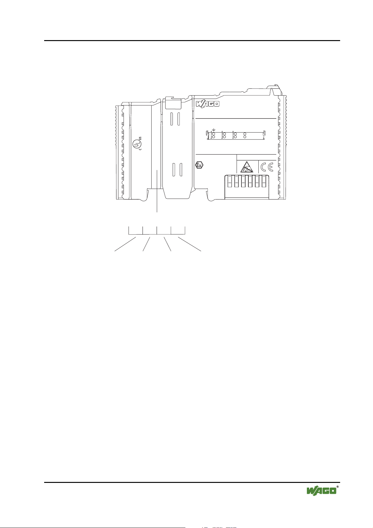
2.3 Manufacturing Number
The production number is part of the lateral marking on the component.
Hansastr. 27
D-32423 Minden
The WAGO-I/O-SYSTEM 750 • 13
Manufacturing Number
ITEM-NO.:750-400
2DI 24V DC 3.0ms
2
0.08-2.5mm
24V DC
CL I DIV 2
AWG 28-14
55°C max ambient
Grp. A B C D
op temp code T4A
24246
LISTED 22ZA AND 22XM
0901--02----03
0V 24V DI1
II3G
KEMA 01ATEX1024 X
EEx nA II T4
Di2
PATENTS PENDING
Manufacturing Number
0
9
Calendar
week
1
0
-
Year Software
version
2
0
0
-
Hardware
version
Fig. 2-3: Manufacturing Number g01xx09e
The manufacturing number consists of the production week and year, the
software version (if available), the hardware version of the component, the
firmware loader (if available) and further internal information for
WAGO Kontakttechnik GmbH.
As of calendar week 43/2000, the production number is also printed on the
cover of the configuration and programming interface of the fieldbus coupler
or controller.
WAGO-I/O-SYSTEM 750
DeviceNet
Page 14
14 • The WAGO-I/O-SYSTEM 750
Storage, Consignment and Transport
2.4 Storage, Consignment and Transport
Wherever possible, the components are to be stored in their original packaging. Likewise, the original packaging provides optimal protection during
transport.
When consigning or repacking the components, the contacts must not be
soiled or damaged. The components must be stored and transported in appropriate containers/packaging. Thereby, the ESD information is to be regarded.
Statically shielded transport bags with metal coatings are to be used for the
transport of open components for which soiling with amine, amide and silicone has been ruled out, e.g. 3M 1900E.
2.5 Mechanical Setup
2.5.1 Installation Position
Along with horizontal and vertical installation, all other installation positions
are allowed.
Attention
In the case of vertical assembly, an end stop has to be mounted as an additional safeguard against slipping.
WAGO item 249-117/002-000 End stop for DIN 35 rail, 10 mm wide
2.5.2 Total Expansion
The maximum total expansion of a node is calculated as follows:
Quantity Width Components
1 51 mm coupler / controller
64 12 mm bus modules
1 12 mm end stop
- inputs / outputs
- power supply modules
- etc.
sum 831 mm
Warning
The maximal total expansion of a node must not exceed 831 mm
WAGO-I/O-SYSTEM 750
DeviceNet
Page 15

The WAGO-I/O-SYSTEM 750 • 15
Mechanical Setup
2.5.3 Assembly onto Carrier Rail
2.5.3.1 Carrier rail properties
All system components can be snapped directly onto a carrier rail in accordance with the European standard EN 50022 (DIN 35).
Warning
WAGO supplies standardized carrier rails that are optimal for use with the
I/O system. If other carrier rails are used, then a technical inspection and approval of the rail by WAGO Kontakttechnik GmbH must take place.
Carrier rails have different mechanical and electrical properties. For the optimal system setup on a carrier rail, certain marginal terms must be observed:
• The material must be non-corrosive.
• Most components have a contact to the carrier rail to ground electro-magnetic disturbances.
In order to avoid corrosion, this tin-plated carrier rail contact must not form a galvanic cell
with the material of the carrier rail which generates a differential voltage above 0.5 V (saline
solution of 0.3% at 20°C) .
• The carrier rail must optimally support the EMC measures integrated into the system and the
shielding of the bus module connections.
• A sufficiently stable carrier rail should be selected and, if necessary, several assembly points
(every 20 cm) should be used in order to prevent bending and twisting (torsion).
• The geometry of the carrier rail must not be altered in order to secure the safe hold of the
components. In particular, when shortening or mounting the carrier rail, it must not be
crushed or bent.
• The base of the components extends into the profile of the carrier rail. For carrier rails with a
height of 7.5 mm, assembly points (screws) are to be riveted under the node in the carrier rail
(slotted head captive screws or blind rivets).
WAGO-I/O-SYSTEM 750
DeviceNet
Page 16
16 • The WAGO-I/O-SYSTEM 750
Mechanical Setup
2.5.3.2 WAGO DIN Rail
WAGO carrier rails meet the electrical and mechanical requirements.
Item Number Description
210-113 /-112 35 x 7.5; 1 mm; steel yellow chromated; slotted/unslotted
210-114 /-197 35 x 15; 1.5 mm; steel yellow chromated; slotted/unslotted
210-118 35 x 15; 2.3 mm; steel yellow chromated; unslotted
210-198 35 x 15; 2.3 mm; copper; unslotted
210-196 35 x 7.5; 1 mm; aluminum; unslotted
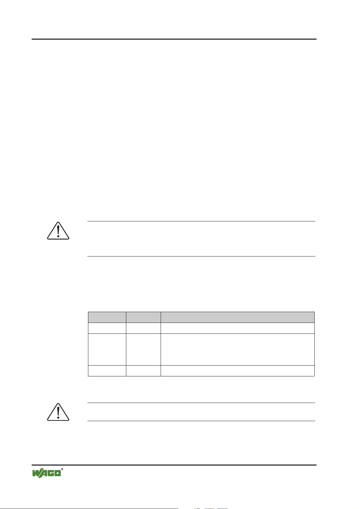
2.5.4 Spacing
The spacing between adjacent components, cable conduits, casing and frame
sides must be maintained for the complete field bus node.
Fig. 2-4: Spacing g01xx13 x
The spacing creates room for heat transfer, installation or wiring. The spacing
to cable conduits also prevents conducted electromagnetic interferences from
influencing the operation.
WAGO-I/O-SYSTEM 750
DeviceNet
Page 17
The WAGO-I/O-SYSTEM 750 • 17
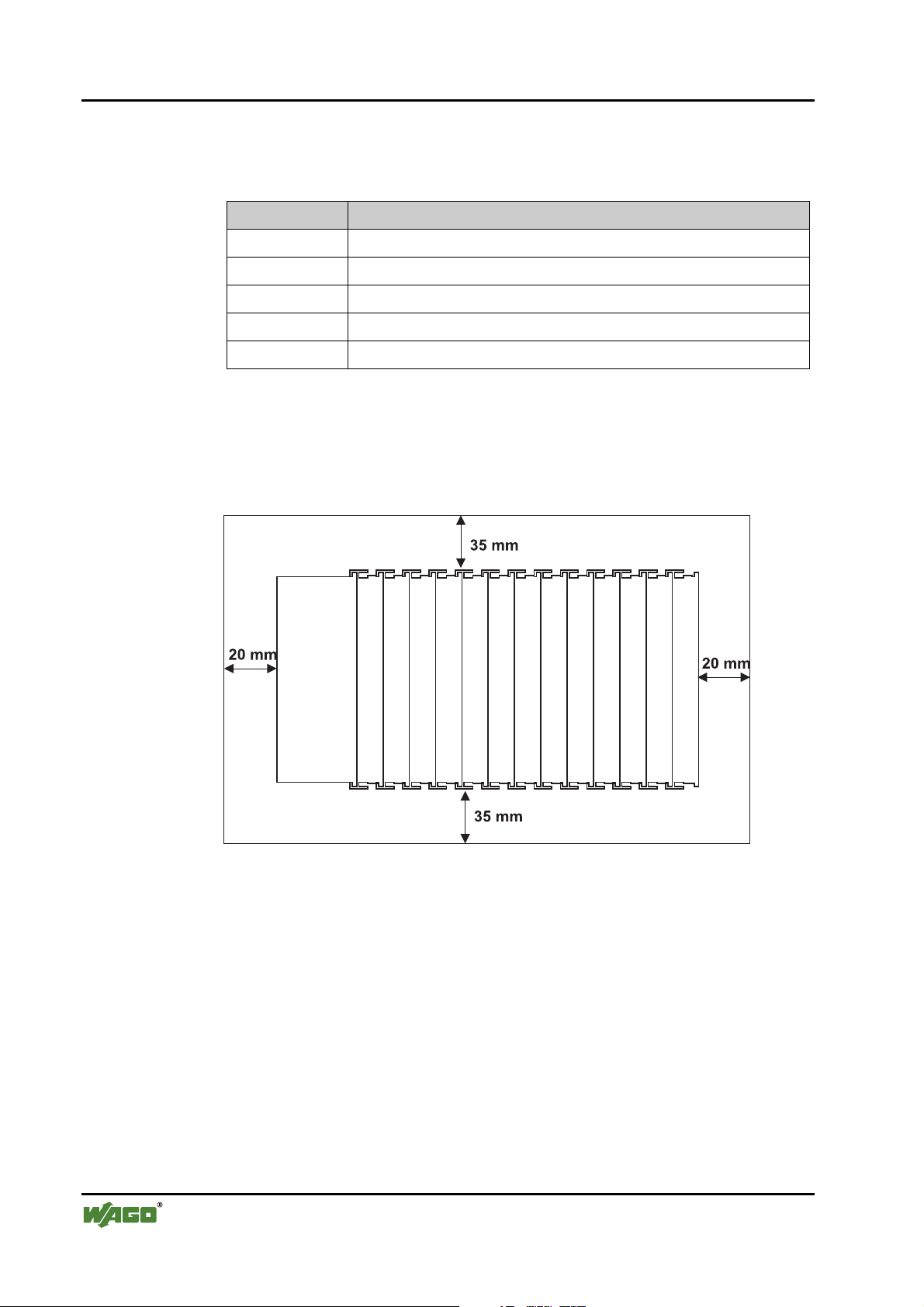
2.5.5 Plugging and Removal of the Components
Warning
Before work is done on the components, the voltage supply must be turned
off.
In order to safeguard the coupler/controller from jamming, it should be fixed
onto the carrier rail with the To do so, push on the upper groove of the locking disc using a screwdriver.
To pull out the fieldbus coupler/controller, release the locking disc by pressing
on the bottom groove with a screwdriver and then pulling the orange colored
unlocking lug.
Mechanical Setup
Fig. 2-5: Coupler/Controller and unlocking lug g01xx12e
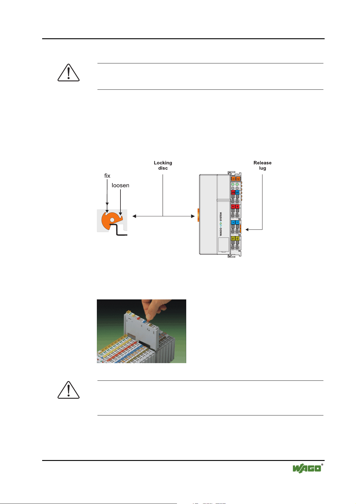
It is also possible to release an individual I/O module from the unit by pulling
an unlocking lug.
Fig. 2-6: removing bus terminal p0xxx01x
Danger
Ensure that an interruption of the PE will not result in a condition which
could endanger a person or equipment!
For planning the ring feeding of the ground wire, please see chapter 2.6.3.
WAGO-I/O-SYSTEM 750
DeviceNet
Page 18

18 • The WAGO-I/O-SYSTEM 750
Mechanical Setup
2.5.6 Assembly Sequence
All system components can be snapped directly on a carrier rail in accordance
with the European standard EN 50022 (DIN 35).
The reliable positioning and connection is made using a tongue and groove
system. Due to the automatic locking, the individual components are securely
seated on the rail after installing.
Starting with the coupler/controller, the bus modules are assembled adjacent to
each other according to the project planning. Errors in the planning of the node
in terms of the potential groups (connection via the power contacts) are recognized, as the bus modules with power contacts (male contacts) cannot be
linked to bus modules with fewer power contacts.
Attention
Always link the bus modules with the coupler / controller, always plug from
above.
Warning
Never plug bus modules from the direction of the end terminal. A ground
wire power contact, which is inserted into a terminal without contacts, e.g. a
4-channel digital input module, has a decreased air and creepage distance to
the neighboring contact in the example DI4.
Always terminate the fieldbus node with an end module (750-600).
WAGO-I/O-SYSTEM 750
DeviceNet
Page 19
2.5.7 Internal Bus / Data Contacts
Communication between the coupler/controller and the bus modules as well as
the system supply of the bus modules is carried out via the internal bus. It is
comprised of 6 data contacts, which are available as self-cleaning gold spring
contacts.
Fig. 2-7: Data contacts p0xxx07x
Warning
Do not connect the I/O module to gold spring contacts in order to avoid soiling or scratches!
The WAGO-I/O-SYSTEM 750 • 19
Mechanical Setup
ESD (Electrostatic Discharge)
The modules are equipped with electronic components that may be destroyed
by electrostatic discharge. When handling the modules, ensure that the environment (persons, workplace and packing) is well grounded. Avoid touching
conductive components, e.g. gold contacts.
WAGO-I/O-SYSTEM 750
DeviceNet
Page 20
20 • The WAGO-I/O-SYSTEM 750
Mechanical Setup
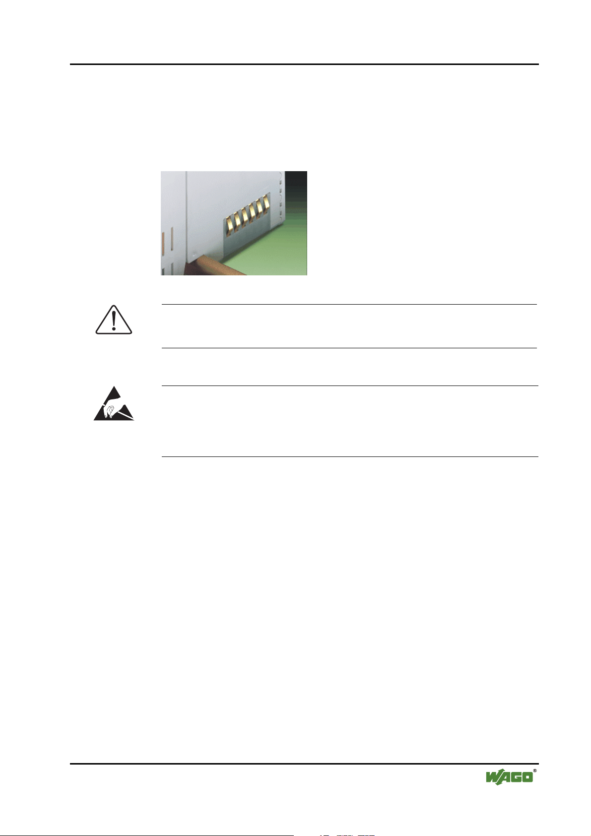
2.5.8 Power Contacts
Self-cleaning power contacts , are situated on the side of the components
which further conduct the supply voltage for the field side. These contacts
come as touchproof spring contacts on the right side of the coupler/controller
and the bus module. As fitting counterparts the module has male contacts on
the left side.
Danger
The power contacts are sharp-edged. Handle the module carefully to prevent
injury.
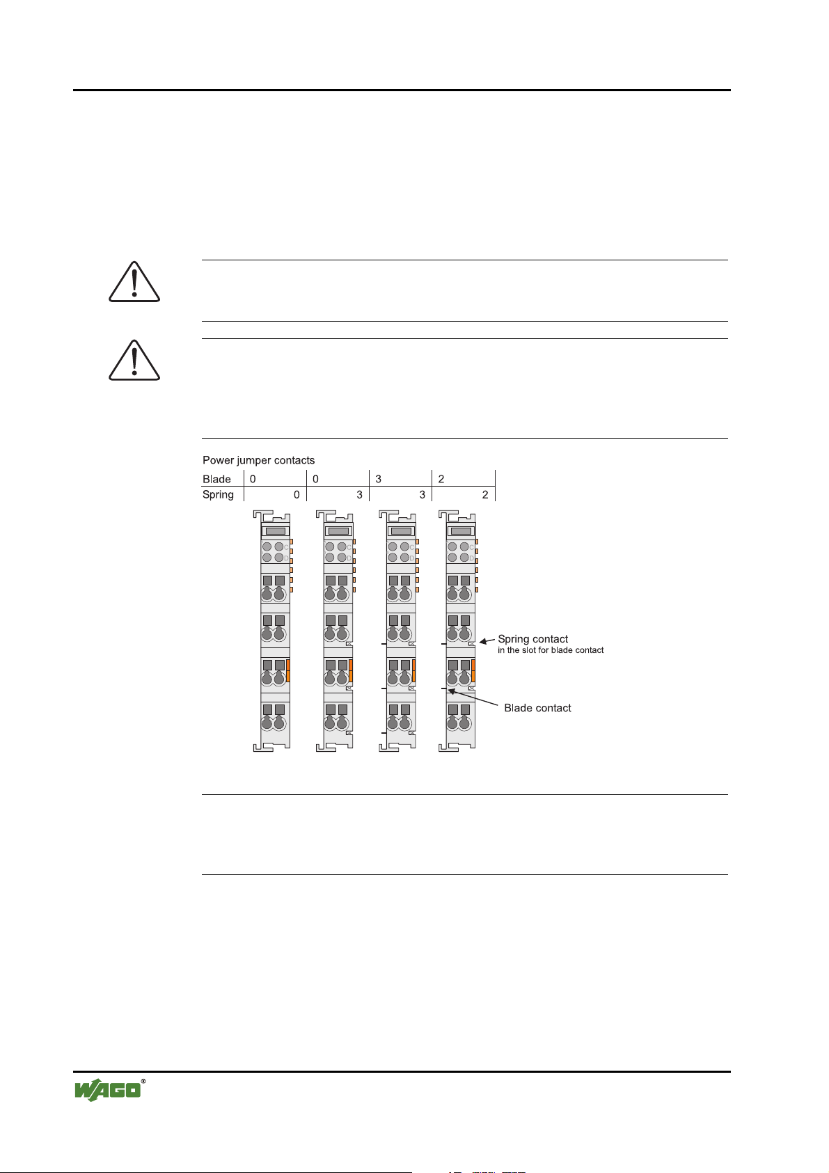
Attention
Please take into consideration that some bus modules have no or only a few
power jumper contacts. The design of some modules does not allow them to
be physically assembled in rows, as the grooves for the male contacts are
closed at the top.
Fig. 2-8: Example for the arrangement of power contacts g0xxx05e
Recommendation
With the WAGO ProServe® Software smartDESIGNER, the assembly of a
fieldbus node can be configured. The configuration can be tested via the integrated plausibility check.
WAGO-I/O-SYSTEM 750
DeviceNet
Page 21
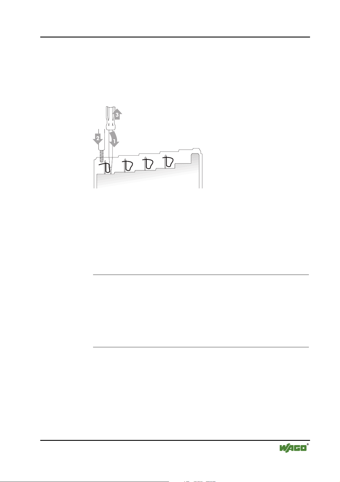
2.5.9 Wire connection
All components have CAGE CLAMP® connections.
The WAGO CAGE CLAMP® connection is appropriate for solid, stranded
and fine–stranded conductors. Each clamping unit accommodates one conductor.
The WAGO-I/O-SYSTEM 750 • 21
Mechanical Setup
Fig. 2-9: CAGE CLAMP® Connection g0xxx08x
The operating tool is inserted into the opening above the connection. This
opens the CAGE CLAMP®. Subsequently the conductor can be inserted into
the opening. After removing the operating tool, the conductor is safely
clamped.
More than one conductor per connection is not permissible. If several conductors have to be laid at a connection, then they should be laid in off-course
wiring; e.g. together with WAGO transfer terminals.
Attention
If it is unavoidable to jointly connect 2 conductors, then a ferrule must be
used.
Ferrule:
Length 8 mm
Nominal cross section
max.
1 mm2 for 2 conductors with 0.5 mm
2
each
WAGO Product 216-103
or products with comparable properties
WAGO-I/O-SYSTEM 750
DeviceNet
Page 22
22 • The WAGO-I/O-SYSTEM 750
Power Supply
2.6 Power Supply
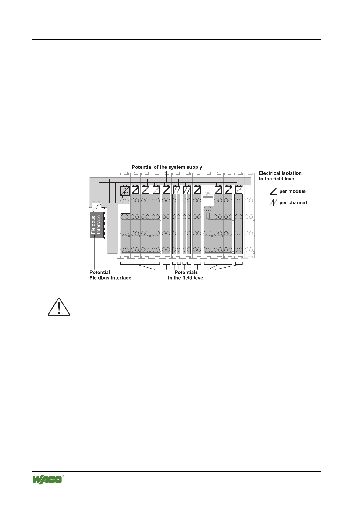
2.6.1 Isolation
Within the fieldbus node, there are three electrically isolated potentials.
• Operational voltage for the fieldbus interface.
• Electronics of the couplers / controllers and the bus modules (internal bus).
• All bus modules have an electrical isolation between the electronics (internal bus, logic) and
the field electronics. Some analogue input modules have each channel electrically isolated,
please see catalogue.
Fig. 2-10: Isolation g0xxx01e
Attention
The ground wire connection must be existent in each group. In order that all
protective conductor functions are maintained under all circumstances, it is
sensible to lay the connection at the beginning and end of a potential group.
(ring format, please see chapter "2.7.3"). Thus, if a bus module comes loose
from a composite during servicing, then the protective conductor connection
is still guaranteed for all connected field devices.
When using a joint power supply unit for the 24 V system supply and the
24 V field supply, the electrical isolation between the internal bus and the
field level is disregarded for the potential group.
WAGO-I/O-SYSTEM 750
DeviceNet
Page 23
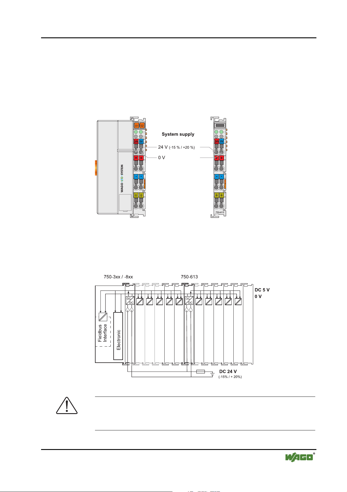
2.6.2 System Supply
2.6.2.1 Connection
The WAGO-I/O-SYSTEM 750 requires a 24 V direct current system supply
(-15% or +20 %). The power supply is provided via the coupler / controller
and, if necessary, in addition via the internal system supply modules
(750-613). The voltage supply is reverse voltage protected.
The WAGO-I/O-SYSTEM 750 • 23
Power Supply
Fig. 2-11: System Supply g0xxx02e
The direct current supplies all internal system components, e.g. coupler/controller electronics, fieldbus interface and bus modules via the internal
bus (5 V system voltage). The 5 V system voltage is electrically connected to
the 24 V system supply.
Fig. 2-12: System Voltage g0xxx06e
Attention
Resetting the system by switching on and off the system supply, must take
place simultaneously for all supply modules (coupler / controller and
750-613).
WAGO-I/O-SYSTEM 750
DeviceNet
Page 24
24 • The WAGO-I/O-SYSTEM 750
Power Supply
2.6.2.2 Alignment
Recommendation
A stable network supply cannot be taken for granted always and everywhere.
Therefore, regulated power supply units should be used in order to guarantee
the quality of the supply voltage.
The supply capacity of the coupler/controller or the internal system supply
module (750-613) can be taken from the technical data of the components.
Internal current consumption*)
Residual current for bus terminals*)
*) cf. catalogue W3 Volume 3, manuals or Internet
Example
Current consumption via system voltage:
5 V for electronics of the bus modules and coupler /
controller
Available current for the bus modules. Provided by
the bus power supply unit. See coupler / controller
and internal system supply module (750-613)
Coupler 750-301:
internal current consumption:350 mA at 5V
residual current for
bus modules: 1650 mA at 5V
sum I(5V) ges: 2000 mA at 5V
The internal current consumption is indicated in the technical data for each bus
terminal. In order to determine the overall requirement, add together the values of all bus modules in the node.
Attention
If the sum of the internal current consumption exceeds the residual current for
bus modules, then an internal system supply module (750-613) must be
placed before the module where the permissible residual current was exceeded.
Example:
A node with a PROFIBUS Coupler 750-333 consists of 20 relay modules (750-517) and 20 digital input modules (750-405).
Current consumption:
20*105 mA = 2100 mA
10* 2 mA = 20 mA
Sum 2120 mA
The coupler can provide 1800 mA for the bus modules. Consequently,
an internal system supply module (750-613), e.g. in the middle of the
node, should be planned.
Recommendation
With the WAGO ProServe® Software smartDESIGNER, the assembly of a
fieldbus node can be configured. The configuration can be tested via the integrated plausibility check.
WAGO-I/O-SYSTEM 750
DeviceNet
Page 25
The WAGO-I/O-SYSTEM 750 • 25
Power Supply
The maximum input current of the 24 V system supply amounts to 500 mA.
The exact electrical consumption (I
) can be determined with the following
(24 V)
formulas:
Coupler/Controller
I(5 V) ges. = Sum of all current consumptions of the connected bus modules
+ internal current consumption coupler / controller
750-613
I(5 V) ges. = Sum of all current consumptions of the connected bus modules
Input current I(24 V) =
5 V / 24 V * I(5 V) ges./ η
η = 0.87 (at nominal load)
Note
If the electrical consumption of the power supply point for the 24 V-system
supply exceeds 500 mA, then the cause may be an improperly aligned node
or a defect.
During the test, all outputs, in particular those of the relay modules, must be
active.
WAGO-I/O-SYSTEM 750
DeviceNet
Page 26
26 • The WAGO-I/O-SYSTEM 750
Power Supply
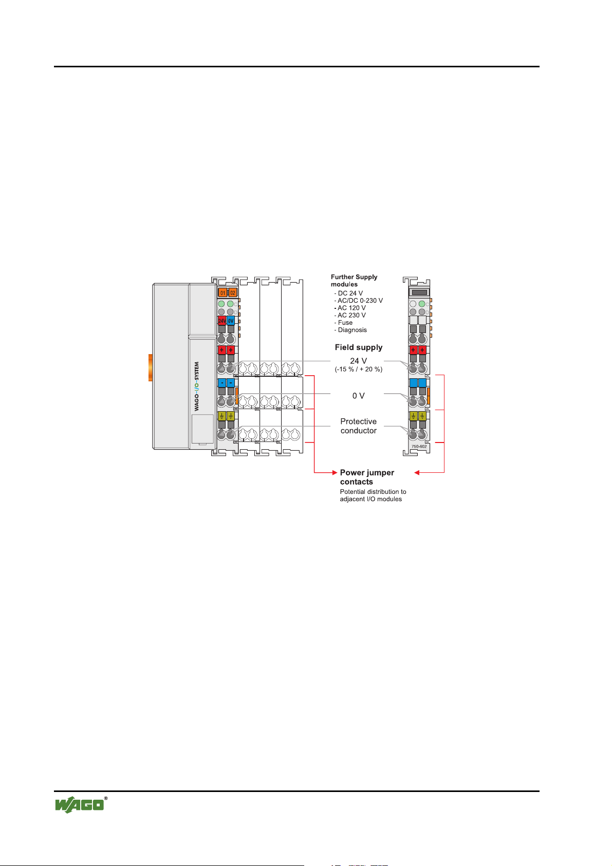
2.6.3 Field Supply
2.6.3.1 Connection
Sensors and actuators can be directly connected to the relevant channel of the
bus module in 1-/4 conductor connection technology. The bus module supplies
power to the sensors and actuators. The input and output drivers of some bus
modules require the field side supply voltage.
The coupler/controller provides field side power (DC 24V). Power supply
modules are available for other potentials, e.g. AC 230 V. Likewise, with the
aid of the power supply modules, various potentials can be set up. The connections are linked in pairs with a power contact.
Fig. 2-13: Field Supply (Sensor / Actuator) g0xxx03e
The supply voltage for the field side is automatically passed on via the power
jumper contacts when assembling the bus modules .
The current load of the power contacts must not exceed 10 A on a continual
basis. The current load capacity between two connection terminals is identical
to the load capacity of the connection wires.
By setting an additional power supply module, the field supply via the power
contacts is disrupted. From there a new power supply occurs which also contains a potential alternation.
WAGO-I/O-SYSTEM 750
DeviceNet
Page 27
2.6.3.2 Fusing
The WAGO-I/O-SYSTEM 750 • 27
Power Supply
Attention
Some bus modules have no or very few power contacts (depends on the I/O
function). Due to this, the passing on of the relevant potential is disrupted. If
a field supply is required for subsequent bus modules, then a power supply
module must be used.
Note the data sheets of the bus modules.
In the case of a node setup with different potentials, e.g. the alteration from
DC 24 V to AC 230V, a spacer module should be used. The optical separation of the potentials acts as a warning to heed caution in the case of wiring
and maintenance works. Thus, the results of wiring errors can be prevented.
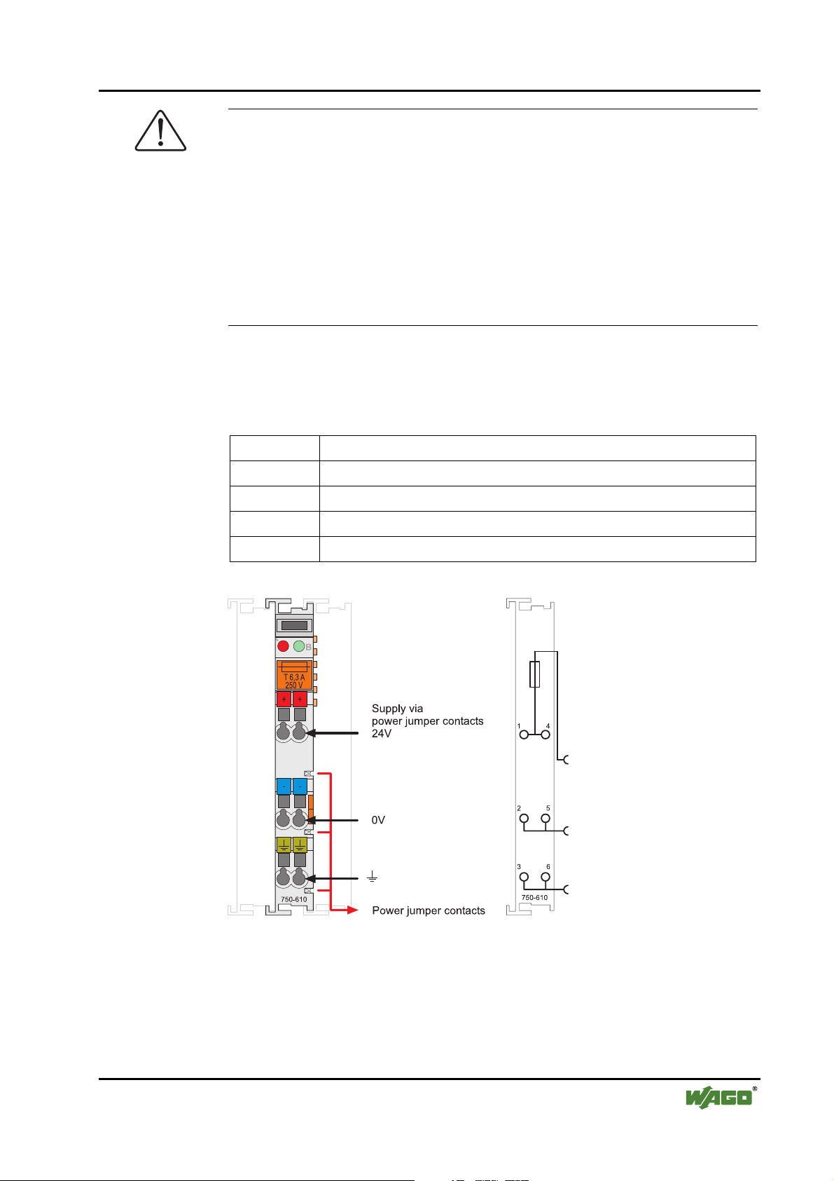
Internal fusing of the field supply is possible for various field voltages via an
appropriate power supply module.
750-601 24 V DC, Supply / Fuse
750-609 230 V AC, Supply / Fuse
750-615 120 V AC, Supply / Fuse
750-610 24 V DC, Supply / Fuse / Diagnosis
750-611 230 V AC, Supply / Fuse / Diagnosis
Fig. 2-14: Supply module with fuse carrier (Example 750-610) g0xxx09x
WAGO-I/O-SYSTEM 750
DeviceNet
Page 28
28 • The WAGO-I/O-SYSTEM 750
Power Supply
Warning
In the case of power supply modules with fuse holders, only fuses with a
maximal dissipation of 1.6 W (IEC 127) must be used.
For UL approved systems only use UL approved fuses.
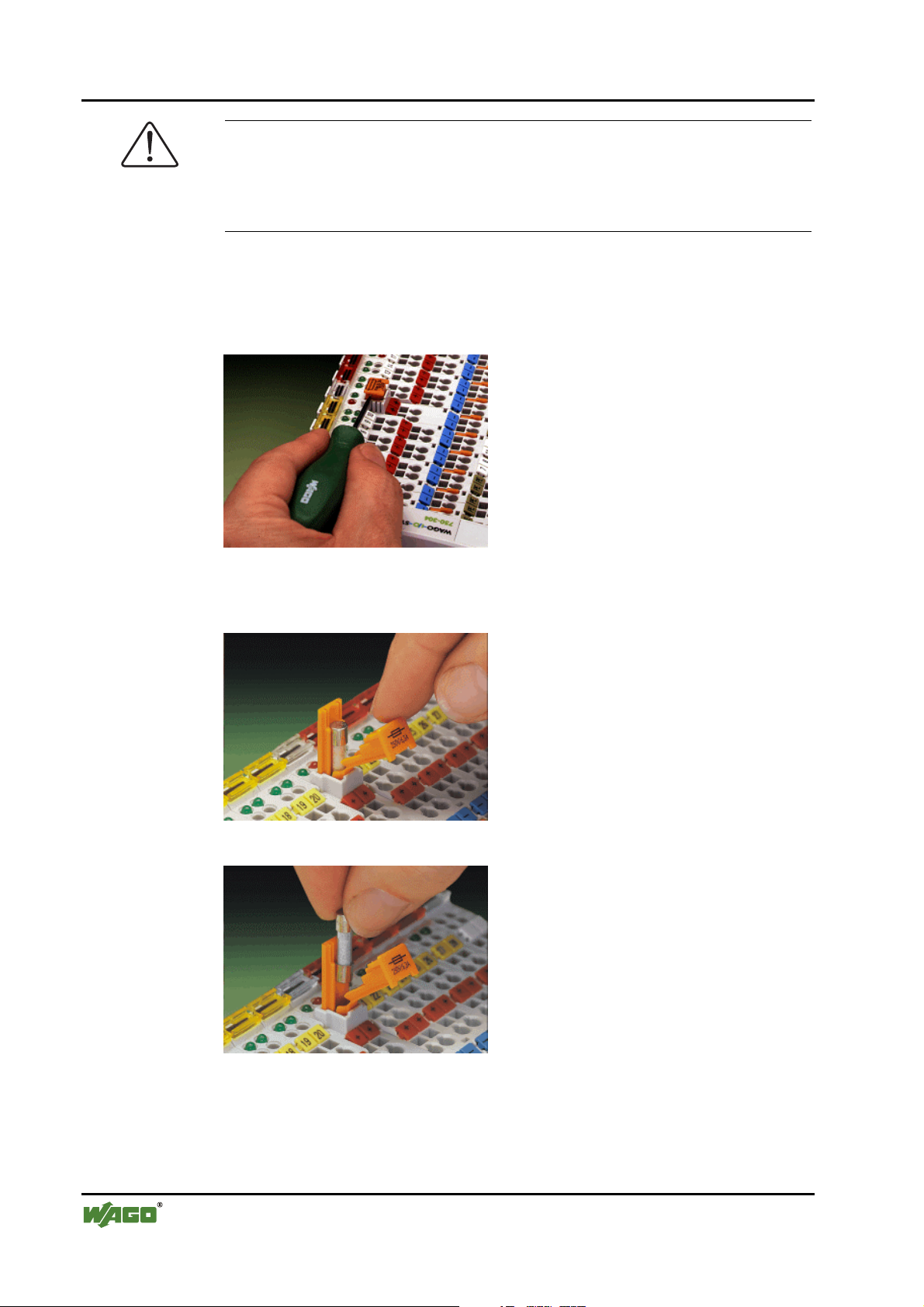
In order to insert or change a fuse, or to switch off the voltage in succeeding
bus modules, the fuse holder may be pulled out. In order to do this, use a
screwdriver for example, to reach into one of the slits (one on both sides) and
pull out the holder.
Fig. 2-15: Removing the fuse carrier p0xxx05x
Lifting the cover to the side opens the fuse carrier.
Fig. 2-16: Opening the fuse carrier p0xxx03x
Fig. 2-17: Change fuse p0xxx04x
After changing the fuse, the fuse carrier is pushed back into its original position.
WAGO-I/O-SYSTEM 750
DeviceNet
Page 29
The WAGO-I/O-SYSTEM 750 • 29
Power Supply
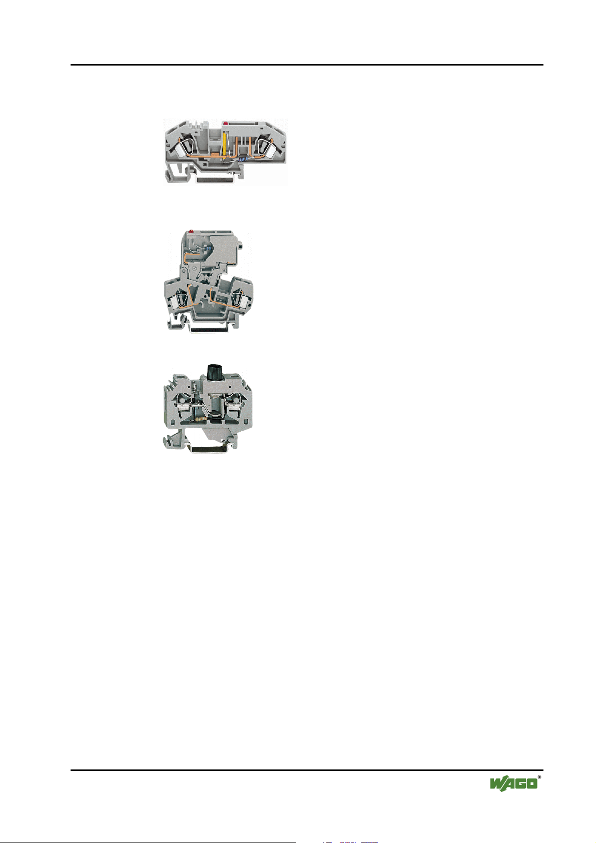
Alternatively, fusing can be done externally. The fuse modules of the WAGO
series 281 and 282 are suitable for this purpose.
Fig. 2-18: Fuse modules for automotive fuses, Series 282 pf66800x
Fig. 2-19: Fuse modules with pivotable fuse carrier, Series 281 pe61100x
Fig. 2-20: Fuse modules, Series 282 pf12400x
WAGO-I/O-SYSTEM 750
DeviceNet
Page 30
30 • The WAGO-I/O-SYSTEM 750
Power Supply
2.6.4 Supplementary power supply regulations
The WAGO-I/O-SYSTEM 750 can also be used in shipbuilding or offshore
and onshore areas of work (e.g. working platforms, loading plants). This is
demonstrated by complying with the standards of influential classification
companies such as Germanischer Lloyd and Lloyds Register.
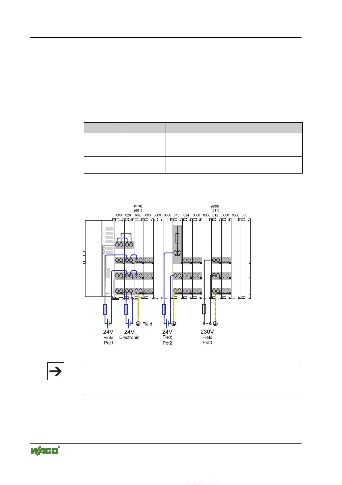
Filter modules for 24-volt supply are required for the certified operation of the
system.
Item No. Name Description
750-626 Supply filter Filter module for system supply and field supply (24 V,
0 V), i.e. for field bus coupler / controller and bus power
supply (750-613)
750-624 Supply filter Filter module for the 24 V- field supply
(750-602, 750-601, 750-610)
Therefore, the following power supply concept must be absolutely complied
with.
Fig. 2-21: Power supply concept g01xx11e
Note
Another potential power terminal 750-601/602/610 must only be used behind
the filter terminal 750-626 if the protective earth conductor is needed on the
lower power contact or if a fuse protection is required.
WAGO-I/O-SYSTEM 750
DeviceNet
Page 31

750-630750-400 750-410 750-401
750-613
750-512 750-512750-616 750-513 750-610 750-552 750-600750-612 750-616
1)
a)
b)
c)
d)
1)
2) 2)
24V
24V
10 A
10 A
L1
L2
L3
N
PE
230V
230V
Main ground bus
Shield (screen) bus
System
Supply
Field
Supply
Field
Supply
1) Separation module
recommended
2) Ring-feeding
recommended
a) Power Supply
on coupler / controller
b) Internal System
Supply Module
c) Supply Module
passive
d)
iagnostics
Supply Module
with fuse carrier/
d
2.6.5 Supply example
Note
The system supply and the field supply should be separated in order to ensure
bus operation in the event of a short-circuit on the actuator side.
The WAGO-I/O-SYSTEM 750 • 31
Power Supply
Fig. 2-22: Supply example g0xxx04e
WAGO-I/O-SYSTEM 750
DeviceNet
Page 32

32 • The WAGO-I/O-SYSTEM 750
Power Supply
2.6.6 Power Supply Unit
The WAGO-I/O-SYSTEM 750 requires a 24 V direct current system supply
with a maximum deviation of -15% or +20 %.
Recommendation
A stable network supply cannot be taken for granted always and everywhere.
Therefore, regulated power supply units should be used in order to guarantee
the quality of the supply voltage.
A buffer (200 µF per 1 A current load) should be provided for brief voltage
dips. The I/O system buffers for ca. 1 ms.
The electrical requirement for the field supply is to be determined individually
for each power supply point. Thereby all loads through the field devices and
bus modules should be considered. The field supply as well influences the bus
modules, as the inputs and outputs of some bus modules require the voltage of
the field supply.
Note
The system supply and the field supply should be isolated from the power
supplies in order to ensure bus operation in the event of short circuits on the
actuator side.
WAGO products
Article No.
787-903 Primary switched - mode, DC 24 V, 5 A
787-904 Primary switched - mode, DC 24 V, 10 A
787-912 Primary switched - mode, DC 24 V, 2 A
288-809
288-810
288-812
288-813
Description
wide input voltage range AC 85-264 V
PFC (Power Factor Correction)
wide input voltage range AC 85-264 V
PFC (Power Factor Correction)
wide input voltage range AC 85-264 V
PFC (Power Factor Correction)
Rail-mounted modules with universal mounting carrier
AC 115 V / DC 24 V; 0,5 A
AC 230 V / DC 24 V; 0,5 A
AC 230 V / DC 24 V; 2 A
AC 115 V / DC 24 V; 2 A
WAGO-I/O-SYSTEM 750
DeviceNet
Page 33

2.7 Grounding
2.7.1 Grounding the DIN Rail
2.7.1.1 Framework Assembly
When setting up the framework, the carrier rail must be screwed together with
the electrically conducting cabinet or housing frame. The framework or the
housing must be grounded. The electronic connection is established via the
screw. Thus, the carrier rail is grounded.
Attention
Care must be taken to ensure the flawless electrical connection between the
carrier rail and the frame or housing in order to guarantee sufficient grounding.
2.7.1.2 Insulated Assembly
The WAGO-I/O-SYSTEM 750 • 33
Grounding
Insulated assembly has been achieved when there is constructively no direct
conduction connection between the cabinet frame or machine parts and the
carrier rail. Here the earth must be set up via an electrical conductor.
The connected grounding conductor should have a cross section of at least
4 mm2.
Recommendation
The optimal insulated setup is a metallic assembly plate with grounding connection with an electrical conductive link with the carrier rail.
The separate grounding of the carrier rail can be easily set up with the aid of
the WAGO ground wire terminals.
Article No. Description
283-609 Single-conductor ground (earth) terminal block make an automatic
contact to the carrier rail; conductor cross section: 0.2 -16 mm2
Note: Also order the end and intermediate plate (283-320)
WAGO-I/O-SYSTEM 750
DeviceNet
Page 34

34 • The WAGO-I/O-SYSTEM 750
Grounding
2.7.2 Function Earth
The function earth increases the resistance capacity against disturbances from
electro-mechanical influences. Some components in the I/O system have a carrier rail contact that dissipates electro-magnetic disturbances to the carrier rail.
Fig. 2-23: Carrier rail contact g0xxx10e
Attention
Care must be taken to ensure the flawless electrical connection between the
carrier rail contact and the carrier rail.
The carrier rail must be grounded.
For information on carrier rail properties, please see chapter 2.5.3.2.
WAGO-I/O-SYSTEM 750
DeviceNet
Page 35

2.7.3 Protective Earth
For the field level, the ground wire is placed onto the lower connection terminals of the power supply terminals and further reached through the lower
power contacts to the neighboring bus terminals. If the bus terminal has the
lower power contact, then the ground wire connection of the field devices can
be directly connected to the lower connection terminals of the bus terminals.
Attention
If the connection of the power contacts for the ground wire within the node is
disrupted, e.g. due to a 4-channel bus terminal, then the potential has to be resupplied.
The ring feeding of the earth potential can increase the system security. In the
event that a bus terminal is ripped out of the potential group, the earth potential is still maintained.
During the ring feeding, the ground wire is connected at the beginning and end
of the potential group.
The WAGO-I/O-SYSTEM 750 • 35
Grounding
Fig. 2-24: Ring-feeding g0xxx07e
WAGO-I/O-SYSTEM 750
DeviceNet
Page 36

36 • The WAGO-I/O-SYSTEM 750
Shielding (screening)
2.8 Shielding (screening)
2.8.1 General
The shielding of the data and signal conductors reduces the electromagnetic
influences thereby increasing the signal quality. Measurement errors, data
transmission errors and even disturbances caused by overvoltage can thus be
avoided.
Attention
Constant shielding is absolutely required in order to ensure the technical
specifications in terms of the measurement accuracy.
The data and signal conductors should be laid separately from all highvoltage cables.
The cable shield is to be laid over a large-scale surface onto the earth potential. With this, incoming disturbances can be easily diverted.
The shielding should be placed over the entrance of the cabinet or housing in
order to already repel disturbances at the entrance.
2.8.2 Bus Conductors
The shielding of the bus conductor is described in the relevant assembly
guideline of the bus system.
2.8.3 Signal Conductors
The bus terminals for analogue signals as well as some interface bus terminals
possess connection terminals for the shield.
Note
Improved shielding can be achieved if the shield is previously placed over a
large-scale surface. For this, we recommend the use of the WAGO shield
connecting system for example.
This is particularly recommendable for systems with large-scale expansions
where it cannot be ruled out that differential currents are flowing or high
pulse currents, i. e. activated by atmospheric discharge, may appear.
WAGO-I/O-SYSTEM 750
DeviceNet
Page 37

The WAGO-I/O-SYSTEM 750 • 37
Assembly Guidelines / Norms
2.8.4 WAGO Shield (Screen) Connecting System
The WAGO shield connecting system is comprised of shield terminal frames,
busbars and diverse assembly feet in order to realize a multitude of constructions. Please see catalogue W3 volume 3 chapter 7.
Fig. 2-25: WAGO Shield (Screen) Connecting System p0xxx08x, p0xxx09x, and p0xxx10x
Fig. 2-26: Application of the WAGO Shield (Screen) Connecting System p0xxx11x
2.9 Assembly Guidelines / Norms
DIN 60204, Electrical equipping of machines
DIN EN 50178 Equipping of high-voltage systems with electronic
components (replacement for VDE 0160)
EN 60439 Low voltage – switch box combinations
WAGO-I/O-SYSTEM 750
DeviceNet
Page 38

38 • Fieldbus Coupler/Controller
Fieldbus Coupler 750-306
3 Fieldbus Coupler/Controller
3.1 Fieldbus Coupler 750-306
This chapter includes:
3.1.1 Description......................................................................................39
3.1.2 Hardware.........................................................................................40
3.1.2.1 View .........................................................................................40
3.1.2.2 Device Supply ..........................................................................41
3.1.2.3 Fieldbus Connection.................................................................42
3.1.2.4 Display Elements......................................................................43
3.1.2.5 Configuration Interface ............................................................44
3.1.2.6 Hardware Address (MAC ID) ..................................................44
3.1.2.7 Setting the Baud Rate...............................................................45
3.1.3 Operating System............................................................................45
3.1.4 Process Image .................................................................................46
3.1.5 Data Exchange ................................................................................47
3.1.5.1 Communication Interfaces .......................................................48
3.1.5.2 Memory Areas..........................................................................48
3.1.5.3 Addressing................................................................................49
3.1.6 Configuration Software...................................................................51
3.1.7 Starting up DeviceNet Fieldbus Nodes...........................................51
3.1.7.1 Connecting the PC and Fieldbus Node ....................................51
3.1.7.2 Setting the MAC ID and Baud Rate.........................................51
3.1.7.3 Configuration with Static Assembly ........................................52
3.1.8 LED Display ...................................................................................56
3.1.8.1 Node Status ..............................................................................57
3.1.8.2 Blink Code................................................................................58
3.1.8.3 Fault Message via the Blink Code of the I/O LED ..................58
3.1.8.4 Supply Voltage Status..............................................................59
3.1.9 Technical Data ................................................................................60
WAGO-I/O-SYSTEM 750
DeviceNet
Page 39

3.1.1 Description
The fieldbus Coupler 750-306 displays the peripheral data of all I/O modules
in the WAGO-I/O-SYSTEM 750 on DeviceNet Feldbus. The data is transmitted with objects.
The bus Coupler determines the physical structure of the node and creates a
process image from this with all inputs and outputs. This could involve a
mixed arrangement of analog (word by word data exchange) and digital (byte
by byte data exchange) modules.
The local process image is subdivided into an input and output data area. The
process data can be read in via the DeviceNet bus and further processed in a
control system. The process output data is sent via the DeviceNet bus.
The data of the analog modules are mapped into the automatical created process image according to the order of their position downstream of the bus Coupler. The bits of the digital modules are compiled to form bytes and also
mapped into the process image attached to the data of the analog modules.
Should the number of digital I/Os exceed 8 bits, the Coupler automatically
starts another byte.
Fieldbus Coupler/Controller • 39
Fieldbus Coupler 750-306
The fieldbus Coupler supports the DeviceNet function Bit-Strobe, whereby the
function is insofar restricted, that only the status byte will be delivered.
WAGO-I/O-SYSTEM 750
DeviceNet
Page 40

40 • Fieldbus Coupler/Controller
Fieldbus Coupler 750-306
3.1.2 Hardware
3.1.2.1 View
Fieldbus
connection
Series 231
(MCS)
DIP switch
for MAC ID
and baud rate
DeviceNet
OVERFL
MS
RUN
BUS OFF
NS
CONNECT
I/O
12345678
ON
750-306
01 02
A
B
24V
+
Ñ
PE PE
0V
Ñ
Status
voltage supply
-Power jumper
C
D
contacts
-System
Data contacts
Supply
24V
0V
+
Supply via
power jumper
contacts
24V
0V
Power jumper
Configuration
contacts
interface
flap
opened
Fig. 3-1: Fieldbus Coupler 750-306 DeviceNet g030600e
The fieldbus Coupler comprises of:
• Supply module with Internal system supply module for the system supply
as well as power jumper contacts for the field supply via I/O module assemblies.
• Fieldbus interface with the bus connection
• DIP switch for baud rate and MAC ID
• Display elements (LED's) for status display of the operation, the bus com-
munication, the operating voltages as well as for fault messages and diagnosis
• Configuration interface
• Electronics for communication with the I/O modules (internal bus) and the
fieldbus interface
WAGO-I/O-SYSTEM 750
DeviceNet
Page 41

3.1.2.2 Device Supply
The supply is made via terminal blocks with CAGE CLAMP® connection.
The device supply is intended both for the system and the field units.
Fieldbus Coupler/Controller • 41
Fieldbus Coupler 750-306
1
5
24V/0V
10nF
DC
DC
Bus
modules
0V
24V
2
6
FIELDBUS INTERFACE
3
7
4
ELECTRONICS
8
750-306
24V
0V
24V
0V
10nF
ELECTRONICS
FIELDBUS
INTERFACE
1) 2)
1) 1M
2) 10nF/500V
Fig. 3-2: Device supply g030601e
The integrated internal system supply module generates the necessary voltage
to supply the electronics and the connected I/O modules.
The fieldbus interface is supplied with electrically isolated voltage from the
internal system supply module.
WAGO-I/O-SYSTEM 750
DeviceNet
Page 42

42 • Fieldbus Coupler/Controller
Fieldbus Coupler 750-306
3.1.2.3 Fieldbus Connection
For the field bus connection, the DeviceNet interface is equipped with a 5 pole
header, its counter-piece being a plug connector (Open Style Connector).
The scope of delivery includes the plug connector 231-305/010-000/050-000
from the WAGO MULTI CONNECTION SYSTEM. The connector has gold
plated contacts and has the signal designations printed at its clamping units.
The table shows the connection diagram, the colours resulting in accordance
with the DeviceNet specification and are identical to the conductor colours of
the DeviceNet cables.
Fieldbus connection
Series 231
(MCS)
V+
CAN_High
drain
CAN_Low
V-
Pin Signal Code Description
5 V+ red 11 ... 25 V
4 CAN_H white CAN Signal
3 Shield Shield connection
2 CAN_L blue CAN Signal
1 V- black 0 V
High
Low
Fig. 3-3: Fieldbus connection, MCS g012500e
For the connection of small conductor cross sections, we recommend to insert
an insulation stop from series 231-670 (white), 231-671 (light grey) or 231672 (dark grey) due to the low kink resistance. This insulation stop prevents a
conductor from kinking when it hits the conductor contact point, and as such
the conductor insulation from being also entered into and clamped in the connection point. Connector marking, housing components, test connectors including cables and header connectors for cable extensions are available.
The connection point is lowered in such a way that after a connector is inserted, installation in an 80 mm high switchbox is possible.
The electrical isolation between the fieldbus system and the electronics is
made via the DC/DC converter and the optoCoupler in the fieldbus.
WAGO-I/O-SYSTEM 750
DeviceNet
Page 43

3.1.2.4 Display Elements
The operating condition of the fieldbus Coupler or node is signalled via light
diodes (LED).
Four LEDs, specific for DeviceNet (OVERFL, RUN, BUSOFF, CONNECT),
indicate the module status (MS) and the network status (NS).
Fieldbus Coupler/Controller • 43
Fieldbus Coupler 750-306
DeviceNet
OVERFL
MS
RUN
BUS OFF
NS
CONNECT
I/O
01
A
B
24V
02
0V
C
D
C
A
Fig. 3-4: Display elements 750-306 g030602x
LED Color Meaning
OVERFL red Errors or faults at the fieldbus Coupler.
RUN green Fieldbus Coupler is ready for operation.
BUS OFF red Error or malfunction at network
CONNECT green Fieldbus Coupler is ready for network communication.
I/O red/
green/
The ‚I/O‘-LED indicates the operation of the node and signals faults
encountered.
orange
A green Status of the operating voltage system
C green Status of the operating voltage – power jumper contacts
WAGO-I/O-SYSTEM 750
DeviceNet
Page 44

44 • Fieldbus Coupler/Controller
Fieldbus Coupler 750-306
3.1.2.5 Configuration Interface
The configuration interface used for the communication with
WAGO-I/O-CHECK or for firmware transfer is located behind the cover flap.
open
flap
Configuration interface
Fig. 3-5: Configuration interface g01xx06e
The communication cable (750-920) is connected to the 4-pole header.
3.1.2.6 Hardware Address (MAC ID)
The DIP switch is used both for parametrizing (setting the baud rate) of the
fieldbus Coupler and for setting the MAC ID.
The MAC-ID (node address) is set with the DIP switches 1 to 6 by 'sliding' the
desired DIP switch to 'ON'.
The binary significance of the individual DIP switches increases according to
the switch number. DIP switch 1 being the lowest bit with the value 20 and
switch 6 the highest bit with the value 25. Therefore the MAC ID 1 is set with
DIP1 = ON, the MAC ID 8 with DIP4 = ON, etc.
For the DeviceNet fieldbus nodes, the node address can be set within the range
from 0 to 63.
ON
12
1
2
345
3
4
5
67
6
7
8
8
Fig. 3-6: Example: Setting of station (node) address MAC ID 1 (DIP 1 = ON) g012540x
ON
The configuration is only read during the power up sequence. Changing the
switch position during operation does not change the configuration of the
buscoupler. Turn off and on the power supply for the fieldbus coupler to accept the DIP switch change.
The default setting is MAC ID 1.
WAGO-I/O-SYSTEM 750
DeviceNet
Page 45

3.1.2.7 Setting the Baud Rate
The fieldbus coupler supports 3 different Baud rates, 125 kBaud, 250 kBaud
and 500 kBaud. DIP switches 7 and 8 are used to set the baud rate.
ON
12
1
2
345
3
4
5
67
6
7
8
8
Fig. 3-7: Example: Setting the baud
rate 250 kBaud (DIP 7 = ON) on a
station (node) with the address MAC
ID 1.
ON
The configuration is only read during the power up sequence. Changing the
switch position during operation does not change the configuration of the
buscoupler. Turn off and on the power supply for the fieldbus Coupler to accept the DIP switch change.
g012541x
Fieldbus Coupler/Controller • 45
Fieldbus Coupler 750-306
Baud rate DIP7 DIP8
125 kBaud
250 kBaud ON OFF
500 kBaud OFF ON
not allowed ON ON
*)
Presetting
*)
OFF OFF
The default setting is Baud rate 125 kB.
3.1.3 Operating System
Following is the configuration of the master activation and the electrical installation of the fieldbus station.
After switching on the supply voltage, the Coupler performs a self-test of all
functions of its devices, the I/O module and the fieldbus interface. Following
this, the I/O modules and the present configuration is determined, whereby an
external, not visible list is generated.
In the event of a fault, the Coupler changes to the "Stop" condition. The "I/O"
LED flashes red. After clearing the fault and cycling power, the Coupler
changes to the "Fieldbus start" status and the "I/O" LED lights up green.
Fig. 3-8: Operating system 750-306 g012113d
WAGO-I/O-SYSTEM 750
DeviceNet
Page 46

46 • Fieldbus Coupler/Controller
Fieldbus Coupler 750-306
3.1.4 Process Image
After powering up, the Coupler recognizes all I/O modules plugged into the
node which supply or wait for data (data width/bit width > 0). In the nodes,
analog and digital I/O modules can be mixed.
The Coupler produces an internal process image from the data width and the
type of I/O module as well as the position of the I/O modules in the node. It is
divided into an input and an output data area.
The data of the digital I/O modules is bit orientated, i.e. the data exchange is
made bit for bit. The analog I/O modules are all byte orientated I/O modules,
i.e. modules where the data exchange is made byte for byte. These I/O modules include, for example, the counter modules, I/O modules for angle and
path measurement as well as the communication modules.
Note
For the number of input and output bits or bytes of the individual I/O modules, please refer to the corresponding I/O module description.
The data of the I/O modules is separated for the local input and output process
image in the sequence of their position after the Coupler in the individual process image.
In the respective I/O area, analog modules are mapped first, then all digital
modules, even if the order of the connected analog and digital modules does
not comply with this order. The digital channels are grouped, each of these
groups having a data width of 1 byte. Should the number of digital I/Os exceed 8 bits, the Coupler automatically starts another byte.
Note
A process image restructuring may result if a node is changed or extended. In
this case, the process data addresses also change in comparison with earlier
ones. In the event of adding a module, take the process data of all previous
modules into account.
WAGO-I/O-SYSTEM 750
DeviceNet
Page 47

3.1.5 Data Exchange
With DeviceNet, the transmission and exchange of data is made using objects.
For a network access on the single objects of the Coupler, it is necessary to
create a connection between the desired participants and to allocate connection
objects.
For an easy and quick set-up of a connection, the DeviceNet fieldbus Coupler
750-306 uses the "Predefined Master/Slave Connection Set", which contains 4
pre-defined connections. For the access on the Coupler the connections only
need to be allocated. The "Predefined Master/Slave Connection Set" confines
itself to pure Master/Slave relationships.
The DeviceNet fieldbus Coupler 750-306 can only communicate via its assigned client and it is a so-called "Group 2 Only Server". The Group 2 Only
Server communicating is only possible via the Group 2 Only Unconnected
Explicit Message Port. These slaves exclusively receive messages defined in
message group 2.
Fieldbus Coupler/Controller • 47
Fieldbus Coupler 750-306
The object configuration for the data transmission is defined by an Assembly
Object. The Assembly Object can be used to group data (e.g. I/O data) into
blocks (mapping) and send this data via one single communication connection.
This mapping results in a reduced number of accesses to the network.
A differentiation is made between "Input-Assemblies" and "OutputAssemblies".
An Input-Assembly reads in data from the application via the network or produces data on the network respectively.
An Output-Assembly writes data to the application or consumes data from the
network respectively.
Various Assembly instances are permanently programmed (static assembly) in
the fieldbus Coupler.
Further information
The Assembly instances for the static assembly are described in chapter
5.5.1.1 "Assembly Instance".
WAGO-I/O-SYSTEM 750
DeviceNet
Page 48

48 • Fieldbus Coupler/Controller
Fieldbus Coupler 750-306
3.1.5.1 Communication Interfaces
For a data exchange, the DeviceNet fieldbus Coupler is equipped with two interfaces:
• the interface to fieldbus (-master) and
• the interface to the bus modules.
Data exchange takes place between the fieldbus master and the bus modules.
Access from the fieldbus side is fieldbus specific.
3.1.5.2 Memory Areas
The Coupler uses a memory space of 256 words (word 0 ... 255) for the physical input and output data.
The division of the memory spaces is identical with all WAGO fieldbus Couplers.
fieldbus coupler
fieldbus
memory area
for input data
word 0
input
modules
word 255
memory area
for output data
word 0
output
modules
word 255
1
2
I/O modules
I
O
Fig. 3-9: Memory areas and data exchange for a fieldbus Coupler g012433e
The Coupler process image contains the physical data of the bus modules in a
storage area for input data and in a storage area for output data (word 0 ... 255
each).
1 The input module data can be read from the fieldbus side.
2 In the same manner, writing to the output modules is possible from the
fieldbus side.
WAGO-I/O-SYSTEM 750
DeviceNet
Page 49

3.1.5.3 Addressing
3.1.5.3.1 Fieldbus Specific
Once the supply voltage is applied, the Assembly Object maps data from the
process image. As soon as a connection is established, a DeviceNet-Master
(Scanner) can address and access the data by "Class", "Instance" and "Attribute".
Data mapping depends on the selected Assembly Instance of the static Assembly.
Further information
The Assembly Instances of the static Assembly are described in chapter
5.5.1.1 "Assembly Instance".
Fieldbus Coupler/Controller • 49
Fieldbus Coupler 750-306
Fieldbus coupler
memory area
for input data
word 0
1
I/O modules
input
modules
word 255
memory area
for output data
word 0
output
modules
word 255
2
I
O
fieldbus
master
Connection
Object
Producer
Consumer
Assembly
Object
Input-
Assemly
Output-
Assemly
Application
Object
Fig. 3-1: Fieldbus specific data exchange for a DeviceNet fieldbus Coupler g012531e
Note
For the number of input and output bits or bytes of the individual I/O modules,
please refer to the corresponding I/O module description.
Note
A process image restructuring may result if a node is changed or extended. In
this case the process data addresses also change in comparison with earlier
ones. In the event of adding a module, take the process data of all previous
modules into account.
WAGO-I/O-SYSTEM 750
DeviceNet
Page 50

50 • Fieldbus Coupler/Controller
Fieldbus Coupler 750-306
Example for static assembly (default assembly):
The default assembly is:
Output1 (I/O Assembly Instance 1)
Input1 (I/O Assembly Instance 4)
In this example, the fieldbus node arrangement looks like this:
1) 1 fieldbus coupler DeviceNet (750-306),
2) 1 digital 4-channel input module (i. e. 750-402),
3) 1 digital 4- channel output module (i. e. 750-504),
4) 1 analog 2- channel output module with 2 bytes per channel (i. e. 750-552),
5) 1 analog 2- channel input module with 2 bytes per channel (i. e. 750-456),
6) 1 End module (750-600).
Input process image:
Default process data, input image (Assembly Class, Instance 4)
Byte .7 .6 .5 .4 .3 .2 .1 .0
0
1
2
3
4
5
1)
DI = Digital Input
2)
DS = Diagnostic Status
DS08 2)DS07 2)DS06 2)DS05 2)DS04 2)DS03 2)DS02 2)DS01
not used DI041)DI031)DI021)DI01
low byte channel 1
high byte channel 1
low byte channel 2
high byte channel 2
Output process image:
Default process data, output image (Assembly Class, Instance 1)
Byte .7 .6 .5 .4 .3 .2 .1 .0
0
1
2
low byte channel 1
high byte channel 1
low byte channel 2
1)
2)
3
4
1)
DO = Digital Output
high byte channel 2
not used DO04
1)
DO031)DO021)DO01
WAGO-I/O-SYSTEM 750
1)
DeviceNet
Page 51

3.1.6 Configuration Software
To enable a connection between the PLC and the fieldbus devices, the interface modules have to be configured with the individual station data.
To this effect, the scope of delivery of WAGO-I/O-SYSTEM 758 includes the
WAGO NETCON software intended for design and configuration, start-up and
diagnosis.
Further configuration software of different manufacturers include, for instance, RSNetWorx.
3.1.7 Starting up DeviceNet Fieldbus Nodes
This chapter shows the step-by-step procedure for starting up a
WAGO DeviceNet fieldbus node.
Attention
This description is given as an example and is limited to the execution of a
local start-up of an individual DeviceNet fieldbus node.
Fieldbus Coupler/Controller • 51
Fieldbus Coupler 750-306
The procedure contains the following steps:
1. Connecting the PC and fieldbus node
2. Setting the MAC ID and baud rate
3. Configuration with static Assembly
3.1.7.1 Connecting the PC and Fieldbus Node
1. Connect the fitted DeviceNet fieldbus node to the DeviceNet fieldbus
PCB in your PC via a fieldbus cable.
The 24 V field bus supply is fed by an external fieldbus network power
supply over the connections V+, V- of the 5-pin fieldbus connector (MCS
Series 231).
2. Start your PC.
3.1.7.2 Setting the MAC ID and Baud Rate
1. Use the DIP switches 1...6 to set the desired node address (MAC ID). The
binary significance of the individual DIP switches increases according to
the switch number.
ON
12
345
67
8
g012443x
Fig. 3-10: Example: Setting the
MAC ID 4 (DIP 3 = ON).
DIP switch Value
0
1
2
3
4
5
6
2
1
2
2
2
3
2
4
2
5
2
WAGO-I/O-SYSTEM 750
DeviceNet
Page 52

52 • Fieldbus Coupler/Controller
Fieldbus Coupler 750-306
2. DIP switches 7 and 8 are used to set the desired baud rate.
ON
12
1
2
345
3
4
5
6
7
8
67
8
ON
g012541x
Fig. 3-11: Example: Setting the baud
rate 250 kBaud (DIP 7 = ON) of the
station with MAC ID 1.
3. Then switch on the Coupler supply voltage.
3.1.7.3 Configuration with Static Assembly
In this example, the software WAGO NETCON is used for the configuration.
Baud rate DIP7 DIP8
125 kBaud
*)
OFF OFF
250 kBaud ON OFF
500 kBaud OFF ON
not allowed ON ON
*)
Presetting
The node in the example consists of the following I/O modules:
1234 5 678
AI AI
516 467
AO AO
550 600
750-306
DI DI DI DI
402
402 516
DODO
DODO DODO
516
Fig. 3-12: Example for a fieldbus node g012552x
1. Starting Software and EDS file load
1. Start the configuration software WAGO NETCON.
2. Load an EDS file for the fieldbus Coupler in WAGO NETCON, i. e.
"4.EDS".
For this click on "File/ Copy EDS" and choose the EDS-file to load.
Note
You can download the EDS files for the fieldbus Coupler from the Internet under: www.wago.com.
Upon downloading the EDS file into WAGO NETCON, you can create a
new project and start configuring your network.
WAGO-I/O-SYSTEM 750
DeviceNet
Page 53

Fieldbus Coupler/Controller • 53
Fieldbus Coupler 750-306
2. Create a new project
1. Enter the "File" menu and click on menu point "New".
2. Select "DeviceNet" as the fieldbus system and confirm your selection by
clicking on the "OK" button.
Fig. 3-13: Select fieldbus p112501d
3. Enter Master
1. Enter a fieldbus master on the surface by clicking on the „Master“ menu
point in the "Insert" menu.
A dialog window opens in which you can select the DeviceNet fieldbus card
in your PC.
Fig. 3-14: Select the DeviceNet fieldbus PCB / Insert Master p1x2602d
2. For the DeviceNet Master interface card, click in the left-hand selection
window on the corresponding entry to mark it.
3. Take the Master into the right-hand window by clicking on the "Add" but-
WAGO-I/O-SYSTEM 750
DeviceNet
ton and confirm by clicking on the "OK" button.
Now the fieldbus master is shown on the surface as a graphic.
Page 54

54 • Fieldbus Coupler/Controller
Fieldbus Coupler 750-306
4. Add a slave
1. Enter a fieldbus slave on the surface by clicking on the “Device” menu
point in the "Insert" menu.
The mouse pointer changes to the letter D with an arrow.
2. Move this mouse pointer to the graphic display of the fieldbus, then click
on the left-hand mouse key.
A dialog window opens permitting you to select a DeviceNet device.
Fig. 3-15: Insert slave p012501d
3. For the fieldbus Coupler 750-306 click in the left-hand selection window
on the corresponding entry to mark it.
4. Take this into the right-hand window by clicking on the "Add" button and
confirm by clicking on the "OK" button.
The configuration is displayed on the surface as a graphic.
Fig. 3-16: Configuration p012502d
WAGO-I/O-SYSTEM 750
DeviceNet
Page 55

Fieldbus Coupler/Controller • 55
Fieldbus Coupler 750-306
5. Device configuration
1. To configure the device, click on its graphic to mark it, then click on the
menu point “Device configuration” in the "Settings" menu.
A dialog window opens permitting you to proceed with the desired settings.
Fig. 3-17: Device Configuration p112505d
6. Load configuration
1. To load the set configuration in the interface card, click on the master’s
graphic to mark it, then click on the “Download” menu point in the "Online" menu.
WAGO-I/O-SYSTEM 750
DeviceNet
Page 56

56 • Fieldbus Coupler/Controller
Fieldbus Coupler 750-306
3.1.8 LED Display
The Coupler possesses several LEDs for on site display of the Coupler operating status or the complete node.
DeviceNet
OVERFL
MS
RUN
BUS OFF
NS
CONNECT
I/O
01
A
B
24V
02
0V
C
D
C
A
Fig. 3-18: Display elements 750-306 g030602x
The module status (MS) and the network status (NS) can be displayed by the
top 4 LED’s. They react as described in the table.
Module status (MS)
OVERFL
(red)
off off no power No power supply to the device.
off on device operational The device operates correctly.
off blinking device in standby The device needs to be configured or has been partly
blinking off minor fault A minor fault has occurred. It exists a diagnostics.
on off unrecoverable fault The device is defective, needs to be serviced or
blinking blinking device self testing The device performs a built-in check.
RUN
(green)
State of device Meaning
configured.
replaced.
Table 3-1: Fault and status displays: MS
Network status (NS)
BUSOFF
(red)
off off not powered, not online No power supply to the device / fieldbus supply /
off blinking online, not connected The device operates correctly at the fieldbus. How-
off on link ok online, connec-
blinking off connection time out A minor fault has occurred (e.g. EPR is unequal 0
on off critical link failure The device has detected a fault (duplicated MAC ID
CONNECT
(green)
State of device Meaning
DeviceNet cable not connected and „Duplicate MAC
ID detection“ is not yet completed.
ever, it has not yet been integrated by a scanner.
ted
The device operates correctly at the fieldbus. At
least one connection to another device has been
established.
during a polling connection, slave is not polled any
longer).
check error). It is unable to perform any more functions in the network.
Table 3-2: Fault and status displays: NS
WAGO-I/O-SYSTEM 750
DeviceNet
Page 57

3.1.8.1 Node Status
LED Color Meaning
Fieldbus Coupler/Controller • 57
Fieldbus Coupler 750-306
IO red /green
/ orange
The 'I/O' LED indicates the node operation and signals faults occurring.
The Coupler starts after switching on the supply voltage. The "I/O" LED
flashes red. Following an error free start up, the "I/O" LED changes to a green,
steady light.
In the case of a fault the "I/O" LED continues blinking red. The fault is cyclically displayed with the blink code.
Switching on
the power supply
Coupler/Controller starts up
“I/O”-LED is blinking
Test o.k.?
Yes
No
“I/O” LED
1st flash sequence
(Introduction of the
error indication)
1st break
“I/O” LED
2nd flash sequence
Error code
(Number of flash cycles)
2nd break
“I/O” LED
“I/O”-LED is shining
ready for operation
3rd flash sequence
Error argument
(Number of flash cycles)
Fig. 3-19: Signalling the LED's node status g012111e
After overcoming a fault, restart the Coupler by cycling the power.
I/O Meaning
green Data cycle on the internal bus
off No data cycle on the internal bus
red Coupler hardware defective
red
blinks
red
blinks cyclically
When starting: internal bus is initialized
During operation: general internal bus fault
Fault message during internal bus reset and internal fault:
WAGO-I/O-SYSTEM 750
DeviceNet
Page 58

58 • Fieldbus Coupler/Controller
Fieldbus Coupler 750-306
3.1.8.2 Blink Code
Detailed fault messages are displayed with the aid of a blink code. A fault is
cyclically displayed with up to 3 blink sequences.
• The first blink sequence (approx. 10 Hz) starts the fault display.
• The second blink sequence (approx. 1 Hz) following a pause. The number
of blink pulses indicates the fault code.
• The third blink sequence (approx. 1 Hz) follows after a further pause. The
number of blink pulses indicates the fault argument.
3.1.8.3 Fault Message via the Blink Code of the I/O LED
Fault argument Fault description
Fault code 1: Hardware and configuration fault
0 EEPROM check sum fault / check sum fault in parameter area of the
flash memory
1 Overflow of the internal buffer memory for the inline code
2 Unknown data type
3 Module type of the flash program memory could not be determined /
is incorrect
4 Fault during writing in the flash memory
5 Fault when deleting the FLASH memory
6 Changed I/O module configuration found after AUTORESET
7 Fault when writing in the serial EEPROM
8 Invalid firmware
9 Checksum error serial EPROM
10 Initial error serial EPROM
11 Read error serial EPROM
12 Timeout error serial EPROM
Fault code 2: Fault in programmed configuration
0 Incorrect table entry
Fault code 3: Internal bus command fault
0 I/O module(s) has (have) identified internal bus command as incor-
rect
Fault code 4: Internal bus data fault
0 Data fault on internal bus or
Internal bus interruption on Coupler
n* (n>0) Internal bus interrupted after I/O module n
WAGO-I/O-SYSTEM 750
DeviceNet
Page 59

Fieldbus Coupler/Controller • 59
Fieldbus Coupler 750-306
Fault code 5: Register communication fault
n* Internal bus fault during register communication with the I/O mod-
ule n
Fault code 6: Fieldbus specific faults
0not used
Fault code 7: I/O module not supported
n* I/O module not supported at position n
* The number of blink pulses (n) indicates the position of the I/O module. I/O modules
without data are not counted (i.e. supply module without diagnosis)
Example: the 13th I/O module is removed.
1. The "I/O" LED generates a fault display with the first blink sequence (approx. 10 Hz).
2. The first pause is followed by the second blink sequence (approx. 1 Hz). The "I/O"
LED blinks four times and thus signals the fault code 4 (internal bus data fault).
3. The third blink sequence follows the second pause. The "I/O" LED blinks twelve
times. The fault argument 12 means that the internal bus is interrupted after the 12
I/O module.
3.1.8.4 Supply Voltage Status
LED Color Meaning
A green Status of the operating voltage – system
C green Status of the operating voltage – power jumper contacts
There are two green LED’s in the Coupler supply section to display the supply
voltage. The left LED (A) indicates the 24 V supply for the Coupler. The right
hand LED (C) signals the supply to the field side, i.e. the power jumper contacts.
th
WAGO-I/O-SYSTEM 750
DeviceNet
Page 60

60 • Fieldbus Coupler/Controller
Fieldbus Coupler 750-306
3.1.9 Technical Data
System data
Max. no. of nodes 64 with scanner
Max. no. of I/O points ca. 6000 (depends on master)
Transmission medium shielded Cu cable,
Max. length of bus line 100 m ... 500 m
Baud rate 125 kBaud, 250 kBaud, 500 kBaud
BusCoupler connection
Standards and approvals
UL E175199, UL508
KEMA
Certification ODVA
Conformity marking CE
Accessories
EDS files 750-912
Miniature WSB quick marking system
Technical data
Max. number of I/O modules 64
Input process image max. 512 bytes
Output process image max. 512 bytes
Configuration via PC or PLC
Voltage supply DC 24 V (-15 % / + 20 %)
Current consumption
- via power supply terminal
- via CAN interface
Efficiency of the power supply 87 %
Internal power consumption 350 mA at 5 V
Total current for I/O modules 1650 mA at 5 V
Isolation 500 V system/supply
Voltage via power jumper contacts DC 24 V (-15 % / + 20 %)
Current via power jumper contact
Dimensions (mm) W x H x L 51 x 65* x 100 (*from top edge of mounting rail)
Weight ca. 195 g
EMC interference resistance acc. EN 50082-2 (95)
EMC interference transmission acc. EN 50081-2 (94)
trunk line: AWG 15, 18 (2x 0.82mm
drop line: AWG 22, 24 (2x0.2mm
(depends on baud rate / on the cable)
5-pole male connector, series 231 (MCS)
female connector 231-305/010-000/050-000
is included
E198726, UL1604
Clas I Div2 ABCD T4A
01ATEX1024 X
Eex nA II T4
< 500 mA at 24 V
< 120 mA at 11 V
DC 10 A
max
2
+2x1.7mm2)
2
+2x0.32mm2)
WAGO-I/O-SYSTEM 750
DeviceNet
Page 61

3.2 Fieldbus Controller 750-806
This chapter includes:
3.2.1 Description......................................................................................62
3.2.2 Hardware.........................................................................................63
3.2.2.1 View .........................................................................................63
3.2.2.2 Device Supply ..........................................................................64
3.2.2.3 Fieldbus Connection.................................................................65
3.2.2.4 Display Elements .....................................................................66
3.2.2.5 Configuration and Programming Interface ..............................67
3.2.2.6 Operating Mode Switch ...........................................................67
3.2.2.7 Hardware Address (MAC ID) ..................................................68
3.2.2.8 Setting the Baud Rate...............................................................69
3.2.3 Operating System............................................................................70
3.2.3.1 Start-up.....................................................................................70
3.2.3.2 PLC Cycle ................................................................................70
3.2.4 Process Image .................................................................................72
3.2.5 Data Exchange ................................................................................73
3.2.5.1 Communication Interfaces .......................................................74
3.2.5.2 Memory Areas..........................................................................74
3.2.5.3 Addressing................................................................................77
3.2.6 Programming the PFC with WAGO-I/O-PRO 32 ..........................81
3.2.6.1 WAGO-I/O-PRO 32 Library Elements....................................81
3.2.6.2 IEC 61131-3 Program Transfer................................................82
3.2.7 Special DeviceNet Features of the Controller.................................85
3.2.7.1 Connection via the UCMM port ..............................................85
3.2.7.2 Offline Connection Set.............................................................85
3.2.7.3 DeviceNet Shutdown ...............................................................85
3.2.7.4 Dynamic Assembly ..................................................................85
3.2.7.5 Change MAC ID by SW ..........................................................86
3.2.7.6 Heartbeat ..................................................................................86
3.2.7.7 Bit-Strobe .................................................................................86
3.2.8 Configuration Software...................................................................87
3.2.9 Starting-up DeviceNet Fieldbus Nodes...........................................87
3.2.9.1 Connecting the PC and Fieldbus Node ....................................87
3.2.9.2 Setting the MAC ID and Baud Rate.........................................87
3.2.9.3 Configuration with Static and Dynamic Assembly..................88
3.2.10 LED Display ...................................................................................99
3.2.10.2 Blink Code .............................................................................101
3.2.11 Technical Data ..............................................................................103
Feldbus-Koppler/-Controller • 61
Fieldbus Controller 750-806
WAGO-I/O-SYSTEM 750
DeviceNet
Page 62

62 • Feldbus Coupler/Controller
Fieldbus Controller 750-806
3.2.1 Description
The programmable fieldbus Controller 750-806 (short: PFC) combines the
DeviceNet functions of the fieldbus Coupler 750-306 with that of a programmable logic control (PLC).
The application program is created with WAGO-I/O-PRO 32 in accordance
with IEC 61131-3.
All input signals of the sensors are grouped in the Controller.
According to the IEC 61131-3 programming, data processing occurs locally in
the PFC. The link results created in this manner can be put out directly to the
actuators or transmitted to the higher ranking control system via the bus.
The programmer has access to all fieldbus and I/O data.
In the initialization phase, the fieldbus Controller determines the physical
structure of the node and creates a process image from this with all inputs and
outputs. This could involve a mixed arrangement of analog (word by word
data exchange) and digital (byte by byte data exchange) modules.
The local process image is subdivided into an input and output data area.
The data of the analog modules are mapped into the PDOs according to the
order of their position downstream of the bus Coupler. The bits of the digital
modules are compiled to form bytes and also mapped into PDOs. Should the
number of digital I/Os exceed 8 bits, the Coupler automatically starts another
byte.
In addition to the functions of the fieldbus Coupler, the fieldbus Controller
supports the following DeviceNet functions:
• Create Connection via UCMM-Port
• Offline Connection Set
• DeviceNet Shutdown
• Dynamic assembly
• Change MAC ID by SW
• Heartbeat
• Bit-Strobe
WAGO-I/O-SYSTEM 750
DeviceNet
Page 63

3.2.2 Hardware
3.2.2.1 View
Fieldbus
connection
Series 231
(MCS)
DIP switch
for MAC ID
and baud rate
DeviceNet
OVERFL
MS
RUN
BUS OFF
NS
CONNECT
I/O
USR
12345678
ON
750-806
01
A
B
24V
+
Ñ Ñ
Feldbus-Koppler/-Controller • 63
Fieldbus Controller 750-806
Status
voltage supply
02
C
D
0V
-Power jumper
contacts
-System
Data contacts
Supply
24V
0V
+
Supply via
power jumper
contacts
24V
0V
Power jumper
Configuration
and programming
interface
operating
mode switch
flap
contacts
opened
Fig. 3-20: Fieldbus Controller 750-806 DeviceNet g080600e
The fieldbus Controller is comprised of:
• Device supply with an internal system supply module as well as power
jumper contacts for the field supply via assembled I/O modules
• Fieldbus interface with the bus connection
• DIP switch for baud rate and node ID
• Display elements (LEDs) for status display of the operation, the bus com-
munication, the operating voltages as well as for fault messages and diagnosis
• Configuration and programming interface and operating mode switch
• Electronics for communication with the I/O modules (internal bus) and the
WAGO-I/O-SYSTEM 750
DeviceNet
fieldbus interface
Page 64

64 • Feldbus Coupler/Controller
Fieldbus Controller 750-806
3.2.2.2 Device Supply
The voltage supply is fed in via the terminals with the CAGE CLAMP® connection. Device supply is intended for system supply and field side supply.
5
1
24V/0V
10nF
DC
DC
Bus
modules
0V
24V
6
FIELDBUS INTERFACE
2
7
3
8
4
ELECTRONICS
750-806
24V
0V
24V
0V
10nF
ELECTRONICS
FIELDBUS
INTERFACE
1) 1M
2) 10nF/500V
Fig. 3-21: Device supply g080601e
The integrated internal system supply module generates the necessary voltage
to supply the electronics and the connected I/O modules.
The fieldbus interface is supplied with electrically isolated voltage from the
internal system supply module.
1) 2)
WAGO-I/O-SYSTEM 750
DeviceNet
Page 65

3.2.2.3 Fieldbus Connection
The scope of delivery includes the plug connector 231-305/010-000/050-000
from the WAGO MULTI CONNECTION SYSTEM. The connector has gold
plated contacts and has the signal designations printed at it clamping units.
The connection diagram shows the table, the colours resulting in accordance
with the DeviceNet specification and are identical to the conductor colours of
the DeviceNet cables.
Fieldbus connection
Series 231
(MCS)
V+
CAN_High
drain
CAN_Low
V-
Feldbus-Koppler/-Controller • 65
Fieldbus Controller 750-806
Pin Signal Code Description
5 V+ red 11 ... 25 V
4 CAN_H white CAN Signal
3 Shield Shield connection
2 CAN_L blue CAN Signal
1 V- black 0 V
High
Low
Fig. 3-22: Fieldbus connection, MCS g012500e
For the connection of small conductor cross sections, we recommend to insert
an insulation stop from series 231-670 (white), 231-671 (light grey) or 231672 (dark grey) due to the low kink resistance. This insulation stop prevents a
conductor from kinking when it hits the conductor contact point, and as such,
the conductor insulation from being also entered into and clamped in the connection point. Connector marking, housing components, test connectors including cables and heater connectors for cable extensions, are available.
The connection point is lowered in such a way that after a connector is inserted, installation in an 80 mm high switchbox is possible.
The electrical isolation between the fieldbus system and the electronics is
made via the DC/DC converter and the optocoupler in the fieldbus.
WAGO-I/O-SYSTEM 750
DeviceNet
Page 66

66 • Feldbus Coupler/Controller
Fieldbus Controller 750-806
3.2.2.4 Display Elements
The operating condition of the fieldbus Coupler or node is signalled via light
diodes (LED).
Four LED’s, specific for DeviceNet (OVERFL, RUN, BUSOFF, CONNECT),
indicate the module status (MS) or the network status (NS).
DeviceNet
OVERFL
MS
RUN
BUS OFF
NS
CONNECT
I/O
USR
01
A
B
24V
02
0V
C
D
C
A
Fig. 3-23: Display elements 750-806 g080602x
LED Color Meaning
OVERFL red Errors or faults at the fieldbus Coupler.
RUN green Fieldbus Coupler is ready for operation.
BUS OFF red Error or malfunction at network
CONNECT green Fieldbus Coupler is ready for network communication.
IO red
/green /
The 'I/O'-LED indicates the operation of the node and signals faults
encountered.
orange
USR red
/green /
The 'USR' LED can be selected by a user program in a programmable fieldbus Controller
orange
A green Status of the operating voltage system
C green Status of the operating voltage – power jumper contacts
WAGO-I/O-SYSTEM 750
DeviceNet
Page 67

3.2.2.5 Configuration and Programming Interface
The configuration and programming interface is located behind the cover flap.
This is used to communicate with WAGO-I/O-CHECK and
WAGO-I/O-PRO 32 as well as for firmware transfer.
open
flap
Configuration and programming interface
Fig. 3-24: Configuration and programming interface g01xx07e
The communication cable (750-920) is connected to the 4-pole header.
Feldbus-Koppler/-Controller • 67
Fieldbus Controller 750-806
3.2.2.6 Operating Mode Switch
The operating mode switch is located behind the cover flap beside the configuration and programming interface.
open
flap
Fig. 3-25: Operating mode switch g01xx10e
The switch is a push/slide switch with 3 settings and a hold-to-run function.
Operating mode switch Function
From middle to top position Activate program processing (RUN)
From top to middle position Stop program processing (STOP)
Lower position, bootstrap For original loading of firmware,
Run
Update firmware
not necessary for user
Stop
mode switch
Reset
(pushing down)
Push down
(i.e.with a screwdriver)
An operating mode is internally changed at the end of a PLC cycle.
WAGO-I/O-SYSTEM 750
DeviceNet
Hardware reset
All outputs are reset; variables are set to 0 or to FALSE
or to an initial value.
The hardware reset can be performed with STOP as well
as RUN in any position of the operating mode switch!
Page 68

68 • Feldbus Coupler/Controller
Fieldbus Controller 750-806
Attention
If outputs are set when switching over the operating mode switch from RUN
to STOP, they remain set! Switching off the software side i.e. by initiators,
are ineffective, because the program is no longer processed.
Note
With "GET_STOP_VALUE" (library "System.lib") WAGO-I/O-PRO 32
provides a function which serves to recognize the last cycle prior to a program stop giving the user the possibility to program the behavior of the Controller in case of a STOP. With the aid of this function the Controller outputs
can be switched to a safe condition.
3.2.2.7 Hardware Address (MAC ID)
The DIP switch is used both for parametrizing (setting the baud rate) of the
fieldbus controller and for setting the MAC ID.
The MAC-ID (node address) is set with the DIP switches 1 to 6 by 'sliding' the
desired DIP switch to 'ON'.
The binary significance of the individual DIP switches increases according to
the switch number. DIP switch 1 being the lowest bit with the value 20 and
switch 6 the highest bit with the value 25. Therefore the MAC ID 1 is set with
DIP1 = ON, the MAC ID 8 with DIP4 = ON, etc.
For the DeviceNet fieldbus nodes the node address can be set within the range
from 0 to 63.
ON
12
1
2
345
3
4
5
67
6
7
8
8
Fig. 3-26: Example: Setting of station (node) address MAC ID 1 (DIP 1 = ON) g012540x
ON
The configuration is only read during the power up sequence. Changing the
switch position during operation does not change the configuration of the
buscoupler. Turn off and on the power supply for the fieldbus controller to accept the DIP switch change.
The default setting is MAC ID 1.
WAGO-I/O-SYSTEM 750
DeviceNet
Page 69

3.2.2.8 Setting the Baud Rate
The fieldbus controller supports 3 different Baud rates, 125 kBaud, 250 kBaud
and 500 kBaud. DIP switches 7 and 8 are used to set the baud rate.
ON
12
1
2
345
3
4
5
67
6
7
8
8
ON
g012541x
Fig. 3-27: Example: Setting the baud
rate 250 kBaud (DIP 7 = ON) on a
station (node) with the address MAC
ID 1.
The configuration is only read during the power up sequence. Changing the
switch position during operation does not change the configuration of the
buscoupler. Turn off and on the power supply for the fieldbus controller to accept the changing.
Feldbus-Koppler/-Controller • 69
Fieldbus Controller 750-806
Baudrate DIP7 DIP8
125 kBaud
*)
OFF OFF
250 kBaud ON OFF
500 kBaud OFF ON
not allowed ON ON
*)
Presetting
The default setting is Baud rate 125 kB.
WAGO-I/O-SYSTEM 750
DeviceNet
Page 70

70 • Feldbus Coupler/Controller
Fieldbus Controller 750-806
3.2.3 Operating System
3.2.3.1 Start-up
The Controller starts-up after switching on the supply voltage or after a hardware reset. The PLC program in the flash memory is transferred to the RAM.
This is followed by the initialization of the system. The Controller determines
the I/O modules and the present configuration. The variables are set to 0 or to
FALSE or to an initialization value given by the PLC program. The flags retain their status. The "I/O" LED blinks red during this phase.
Following an error free start-up, the Controller changes over to the "RUN"
mode. The "I/O" LED lights up green.
A PLC program does not yet exist in the flash memory when delivered. The
Controller start-up is described without initializing the system. It then behaves
as a Coupler.
3.2.3.2 PLC Cycle
The PLC cycle starts following an error free start-up when the operating mode
switch is in the top position or by a start command from the
WAGO-I/O-PRO 32. The input and output data of the fieldbus and the I/O
modules as well as the times are read. Subsequently, the PLC program in the
RAM is processed followed by the output data of the fieldbus and the I/O
modules in the process image. Operating system functions, amongst others, for
diagnosis and communication are performed and the times are updated at the
end of the PLC cycle. The cycle starts again with the reading in of the input
and output data and the times.
The change of the operating mode (STOP/RUN) is made at the end of a PLC
cycle.
The cycle time is the time from the start of the PLC program to the next start.
If a loop is programmed within a PLC program, the PLC running time and
thus the PLC cycle are extended correspondingly.
The inputs, outputs and times are not updated during the processing of the
PLC program. This update occurs in a defined manner only at the end of the
PLC program. For this reason it is not possible to wait for an event from the
process or the elapse of a time within a loop.
WAGO-I/O-SYSTEM 750
DeviceNet
Page 71

Switching on the
supply voltage
Feldbus-Koppler/-Controller • 71
Fieldbus Controller 750-806
“I/O” LED
is blinking
orange
“I/O” LED
is blinking
red
PLC cycle
Is a PLC
program in the Flash
memory ?
Yes
PLC program transfer
from the flash memory to RAM
Determination of the I/O modules
and the configuration
Initialization
of the system
Test o.k.?
No
Yes
Operating mode
RUN
Reading inputs, outputs and times
No
Variables are set to 0 or FALSE
or to their initial value,
flags remain in the same status.
Stop
operating mode switch
is in the top position or
STOP
start command in
WAGO-IO- 32:
Online/Start Online/Stop
Fieldbus data,
data of I/O modules
Determination of the I/O modules
and the configuration
No
Test o.k.?
Yes
PRO
or
“I/O” LED
is shining
green
PLC program in the RAM
is processed
Writing outputs
Operating system functions,
updating times
Operating mode
RUN
Fieldbus data,
data of I/O modules
operating mode switch
is in the top position or
STOP
start command in
WAGO-IO- 32:
Online/Start Online/Stop
PRO
or
Fieldbus start
behaviour as a coupler
Fig. 3-28: Controller operating system g012941d
WAGO-I/O-SYSTEM 750
DeviceNet
Page 72

72 • Feldbus Coupler/Controller
Fieldbus Controller 750-806
3.2.4 Process Image
After switching on, the Controller recognizes all I/O modules plugged into the
node which supply or wait for data (data width/bit width > 0). In nodes, analog
and digital I/O modules can be mixed.
The Controller produces an internal process image from the data width and the
type of I/O module as well as the position of the I/O modules in the node. It is
divided into an input and an output data area.
The data of the digital I/O modules is bit orientated, i.e. the data exchange is
made bit for bit. The analog I/O modules are all byte orientated I/O modules,
i.e. those where the data exchange is made byte for byte. These I/O modules
include, for example, the counter modules, I/O modules for angle and path
measurement as well as the communication modules.
Note
For the number of input and output bits or bytes of the individually activated
on I/O modules please refer to the corresponding I/O module description.
The data of the I/O modules is separated from the local input and output process image in the sequence of their position after the controller in the individual
process image.
In the respective I/O area, first of all analog modules are mapped, then all
digital modules, even if the order of the connected analog and digital modules
does not comply with this order. The digital channels are grouped, each of
these groups having a data width of 1 byte. Should the number of digital I/Os
exceed 8 bits, the Controller automatically starts another byte.
Note
A process image restructuring may result if a node is changed or extended. In
this case, the process data addresses also change in comparison with earlier
ones. In the event of adding modules, take the process data of all previous
modules into account.
The process image for the physical bus module data is identical with that of
the WAGO DeviceNet fieldbus Coupler.
With the Controller, the data of the PFC variables are filled into the process
image, separated according to input and output data.
WAGO-I/O-SYSTEM 750
DeviceNet
Page 73

3.2.5 Data Exchange
With DeviceNet, the transmission and exchange of data is made using objects.
For a network access on the single objects, it is necessary to create a connection between the desired participants and to allocate connection objects.
The DeviceNet fieldbus Controller 750-806 can communicate via the UCMMPort (Unconnected Message Manager Port).
The UCMM-Port permits a dynamic connection via one or several connections
from one or more clients.
The object configuration for the data transmission is defined by the Assembly
Object. The Assembly Object can be used to group data (e.g.: I/O data) to
form blocks (mapping) and send this data via one single communication connection. This mapping results in a reduced number of accesses to the network.
A differentiation is made between input and output assemblies.
An Input Assembly reads data from the application via the network or produces data on the network respectively.
An Output Assembly writes data to the application or consumes data from the
network respectively.
Feldbus-Koppler/-Controller • 73
Fieldbus Controller 750-806
Various Assembly instances are permanently programmed (static assembly) in
the fieldbus Controller.
Further information
The Assembly instances for the static Assembly are described in chapter
5.5.1.1 "Assembly Instance".
In addition to the static assembly, dynamic assembly can also be used with the
fieldbus Controller. The dynamic assembly can be used to set up Assembly Instances in which process data from various application objects can be configured as required.
Further information
For information regarding the dynamic Assembly, please refer to chapter
3.2.7.4 "Dynamic Assembly".
WAGO-I/O-SYSTEM 750
DeviceNet
Page 74

74 • Feldbus Coupler/Controller
Fieldbus Controller 750-806
3.2.5.1 Communication Interfaces
For a data exchange, the DeviceNet fieldbus Controller is equipped with three
interfaces:
• the interface to fieldbus (-master),
• the PLC functionality of the PFC (CPU) and
• the interface to the bus modules
Data exchange takes place between the fieldbus master and the bus modules,
between the PLC functionality of the PFC (CPU) and the bus modules as well
as between the fieldbus master and the PLC functionality of the PFC (CPU).
Data access of the PLC functionality of the PFC (CPU) is via an application
related IEC 61131-3 program and independent on the fieldbus system.
Access from the fieldbus side is fieldbus specific.
3.2.5.2 Memory Areas
The Controller uses a memory space of 256 words (word 0 ... 255) for the
physical input and output data.
The Controller is assigned an additional memory space for mapping the PFC
variables defined according to IEC 61131-3. This extended memory space
(word 256 ... 511 each) is used to map the PFC variables behind the physical
process image.
The division of the memory spaces and the access of the PLC functionality
(CPU) to the process data is identical with all WAGO fieldbus Controllers.
Access is via an application related IEC 61131-3 program and independent on
the fieldbus system.
Access from the fieldbus side is fieldbus specific.
WAGO-I/O-SYSTEM 750
DeviceNet
Page 75

Feldbus-Koppler/-Controller • 75
Fieldbus Controller 750-806
Fig. 3-29: Memory areas and data exchange for a fieldbus Controller g012434d
In its memory space word 0 ... 255, the Controller process image contains the
physical data of the bus modules.
1 The data of the input modules can be read by the CPU and from the field-
bus side.
2 In the same manner, writing to the output modules is possible from the
CPU and from the fieldbus side. The value of the last is written to the output while concurrent writing on an output.
Note
A concurrent writing on an output must be avoided.
Either by using instance 11 of the static assembly (see chapter 0 "
Additional Assembly Instances 10 and 11") or by using the dynamic assembly
(see chapter 3.2.7.4 "Dynamic Assembly").
The PFC variables are filled in the memory space word 256 ... 511 of the process image.
3 The PFC input variables are written in the input memory space from the
4 The variables processed by the CPU via the IEC 61131-3 program are filled
WAGO-I/O-SYSTEM 750
DeviceNet
fieldbus side and read by the CPU for further processing.
in the output memory space and can be read out by the master.
Page 76

76 • Feldbus Coupler/Controller
Fieldbus Controller 750-806
In addition, the Controller offers further memory spaces which, however, cannot be accessed from the fieldbus side:
RAM
Retain
Code
memory
The RAM memory is used to create variables not required for communication with the interfaces but for internal processing, such as
computation of results.
The retain memory is a non-volatile memory, i.e. all values are retained following a voltage failure. The memory management is
automatic. In this memory area, flags for the IEC 61131-3 program
are filed together with variables without memory space addressing or
variables which are explicitly defined with "var retain".
Note
The automatic memory management can cause a data overlap. For
this reason, we recommend not to use a mix of flags and retain variables.
The IEC 61131-3 program is filed in the code memory. The code
memory is a flash ROM. Once the supply voltage is applied, the
program is transmitted from the flash to the RAM memory. After an
error-free start-up, the PFC cycle starts when the operating mode
switch is turned to its upper position or by a start command from
WAGO-I/O-PRO 32.
WAGO-I/O-SYSTEM 750
DeviceNet
Page 77

3.2.5.3 Addressing
3.2.5.3.1 Fieldbus Specific
Once the supply voltage is applied, the Assembly Object maps data from the
process image. As soon as a connection is established, a DeviceNet Master
(scanner) can address and access the data by "Class", "Instance" and "Attribute" or read and/or write the data using I/O connections.
Data mapping depends on the selected Assembly instance of the static assembly or on the application specific determination with the dynamic Assembly.
Further information
The Assembly Instances of the static Assembly are described in chapter
5.5.1.1 "Assembly Instance".
Further information
For information regarding the dynamic Assembly, please refer to chapter
3.2.7.4 "Dynamic Assembly".
Feldbus-Koppler/-Controller • 77
Fieldbus Controller 750-806
Programmable fieldbus controller
memory area
for input data
word 0
input
modules
word 255
word 256
PFC
input
variables
word 511
memory area
word 0
output
modules
word 255
word 256
PFC
output
variables
word 511
131
I/O modules
3
IEC 61131
program
CPU
2
I
4
O
fieldbus
master
Connection
Object
Producer
Consumer
Object directory()
Assembly
Object
Assemly
Assemly
Application
Input-
Output-
Object
Digital I/O,
Analog I/O
for output data
Fig. 3-2: Fieldbus specific data exchange for a DeviceNet fieldbus Controller g012532d
Note
For the number of input and output bits or bytes of the individual I/O modules,
please refer to the corresponding I/O module description.
Note
A process image restructuring may result if a node is changed or extended. In
this case, the process data addresses also change in comparison with earlier
ones. In the event of adding a module, take the process data of all previous
modules into account.
WAGO-I/O-SYSTEM 750
DeviceNet
Page 78

78 • Feldbus Coupler/Controller
Fieldbus Controller 750-806
Example for static assembly (default assembly):
The default assembly is:
Output1 (I/O Assembly Instance 1)
Input1 (I/O Assembly Instance 4)
In this example, the fieldbus node arrangement looks like this:
1) 1 fieldbus Controller DeviceNet (750-806)
2) 1 digital 4-channel input module (i. e. 750-402),
3) 1 digital 4- channel output module (z. B. 750-504),
4) 1 analog 2- channel output module with 2 bytes per channel (i. e. 750-552),
5) 1 analog 2- channel input module with 2 bytes per channel (i. e. 750-456),
6) 1 End module (750-600).
Input process image:
Default process data, input image (Assembly Class, Instance 4)
Byte .7 .6 .5 .4 .3 .2 .1 .0
0
1
2
3
4
5
1)
DI = Digital Input
2)
DS = Diagnostic Status
DS08 2)DS07 2)DS06 2)DS05 2)DS04 2)DS03 2)DS02 2)DS01
not used DI04
low byte channel 1
high byte channel 1
low byte channel 2
high byte channel 2
1)
DI031)DI021)DI01
Output process image:
Default process data, output image (Assembly Class, Instance 1)
Byte .7 .6 .5 .4 .3 .2 .1 .0
0
low byte channel 1
1)
2)
1
2
3
4
1)
DO = Digital Output
high byte channel 1
low byte channel 2
high byte channel 2
not used DO04
1)
DO031)DO021)DO01
WAGO-I/O-SYSTEM 750
1)
DeviceNet
Page 79

3.2.5.3.2 Absolute Addressing
The CPU has direct access to the bus terminal data through absolute addresses.
Addressing begins with the address 0 both with inputs and outputs. The corresponding addresses for bits, bytes and double words (DWord) are derived
from the word addresses.
The structure of the process image is described in chapter 3.2.4 Process Image.
Addressing is done in this structure.
Feldbus-Koppler/-Controller • 79
Fieldbus Controller 750-806
Input data
Output data
3.2.5.3.3 Calculate Addresses
The word address is the basis for calculation (word).
Bit Address
Byte Address
DWord Address
%IW0
word-orientated data
|
%IW
n
%I
n+1
bit-orientated data
|
%I
n+m
%QW0
word-orientated data
|
%QW
n
%Q
n+1
bit-orientated data
|
%Q
n+m
Word address .0 to .15
1st byte: 2 x Word address
2nd byte: 2 x Word address + 1
lower section: Word address (even numbers) / 2
upper section: Word address (odd numbers) / 2, rounded off
3.2.5.3.4 Address Range for I/O Module Data
Data size Address range I/O module data
Bit 0.0
...
0.7
Byte 0 1 2 3 ... 508 509 510 511
Word 0 1 ... 254 255
DWord 0 ... 127
WAGO-I/O-SYSTEM 750
DeviceNet
0.8
...
0.15
1.0
1.7
1.8
...
...
1.15
... 254.0
...
254.7
254.8
...
254.15
255.0
...
255.7
255.8
...
255.15
Page 80

80 • Feldbus Coupler/Controller
Fieldbus Controller 750-806
3.2.5.3.5 Address Range for Fieldbus Variables
Data size Address range fieldbus variables
Bit 256.0
256.7
Byte 512 513 514 515 ... 1020 1021 1022 1023
Word 256 257 ... 510 511
DWord 128 ... 255
256.8
...
256.15
257.0
...
...
257.7
3.2.5.3.6 Address Range for Flags
Data size Address range flags
Bit 0.0
...
0.7
Byte 0 1 2 3 ... 8188 8189 8190 8191
Word 0 1 ... 4094 4095
DWord 0 ... 2047
0.8
...
0.15
1.0
...
1.7
257.8
...
257.15
1.8
...
1.15
... 510.0
...
510.7
... 4094.0
...
4094.7
510.8
...
510.15
4094.8
...
4094.15
511.0
...
511.7
4095.0
...
4095.7
511.8
...
511.15
4095.8
...
4095.15
All flags are non volatile (retain).
3.2.5.3.7 Example for Absolute Addresses
Data size Inputs:
Bit %IX14.0 ... 15 %IX15.0 ... 15
Byte %IB28 %IB29 %IB30 %IB31
Word %IW14 %IW15
DWord %ID7
Data size Outputs:
Bit %QX5.0 ... 15 %QX6.0 ... 15
Byte %QB10 %QB11 %QB12 %QB13
Word %QW5 %QW6
DWord %QD2 (oberer Teil) %QD3 (unterer Teil)
Data size Flags:
Bit %MX11.0 ... 15 %MX12.0 ... 15
Byte %MB22 %MB23 %MB24 %MB25
Word %MW11 %MW12
DWord %MD5 (upper part) %MD6 (lower part)
The character 'X' for single bits can be deleted, e.g.%I14.0, %Q6.10, %M11.7
WAGO-I/O-SYSTEM 750
DeviceNet
Page 81

Feldbus-Koppler/-Controller • 81
3.2.6 Programming the PFC with WAGO-I/O-PRO 32
Due to the IEC 61131 programming of the DeviceNet fieldbus Controller
750-806 you have the option to use the functionality of a PLC beyond the
functions of fieldbus Coupler 750-306.
An application program according to IEC 61131-3 is created using the programming tool WAGO-I/O-PRO 32 (order No.: 759-332/000-002).
This manual, however, does not include a description of how to program with
WAGO-I/O-PRO 32. In contrast, the following chapters are to describe the
special modules for WAGO-I/O-PRO 32 for you to utilize explicitly for programming the DeviceNet fieldbus Controller.
The description also explains transmitting the IEC 61131-3 program into the
Controller and loading a suitable communication driver.
More information
For a detailed description of how to use the software, please refer to the
WAGO-I/O-PRO 32 manual (order No.: 759-122 / 000-002).
Fieldbus Controller 750-806
3.2.6.1 WAGO-I/O-PRO 32 Library Elements
You are offered various libraries for different IEC 61131-3 programming applications in WAGO-I/O-PRO 32. They contain modules for universal use
and can, thereby, facilitate and speed up the creation of your program. As
standard, the library 'standard.lib' is available to you.
The library described in the following is specifically intended for DeviceNet
projects with WAGO-I/O-PRO 32:
• "DevNet. lib"
This library extends the fieldbus Controller 750-806 by the master function.
As a result, it can be programmed in the network as a DeviceNet Master.
Several libraries are loaded on the WAGO-I/O-PRO CD.
Having integrated this library, you have access to its POUs, data types and
global variables which can be used in the same manner as those defined by
yourself.
More information
For a detailed description of the POUs and the software operation, please
refer to the WAGO-I/O-PRO 32 manual (order No.: 759-122 / 000-002).
WAGO-I/O-SYSTEM 750
DeviceNet
Page 82

82 • Feldbus Coupler/Controller
Fieldbus Controller 750-806
3.2.6.2 IEC 61131-3 Program Transfer
Program transfer from the PC to the Controller following programming of the
desired IEC 61131 application can be made in two different ways:
• via the serial interface or
• via the fieldbus.
One suitable communication driver each is required for both types.
More information
For information on the installation of the communication drivers as well as
details regarding the use of the software, please refer to the
WAGO-I/O-PRO 32 manual (order No.: 759-122 / 000-002).
3.2.6.2.1 Transmission via the Serial Interface
Use the WAGO communication cable to produce a physical connection via the
serial interface. This is contained in the scope of delivery of the programming
tool IEC 61131-3, order No.: 759-332/000-002, or can be purchased as an accessory under order No.: 750-920.
Connect the COMX port of your PC with the communication interface of your
Controller via the WAGO communication cable.
A communication driver is required for serial data transmission. In WAGO-
I/O-PRO 32, this driver and its parameters are entered in the "Communica-
tion parameters" dialog.
1. Start the WAGO-I/O-PRO 32 software via ’Start/Programs’ or by double
clicking on the WAGO-I/O-PRO-32 symbol on your desk top.
2. In the "Online" menu click on the "Communication parameters" menu
point.
The dialog "Communication parameters" opens. The basic setting of this
dialog has not yet any entries.
3. In the selection window mark the desired driver on the right-hand dialog
side (i.e. "Serial RS232"), to configure the serial connection between PC
and the Controller).
4. In the center window of the dialog, the following entries have to appear:
- Parity: Even
- Stop bits: 1
If necessary, change the entries accordingly.
You can now commence testing the Controller.
WAGO-I/O-SYSTEM 750
DeviceNet
Page 83

Feldbus-Koppler/-Controller • 83
Fieldbus Controller 750-806
Note
To be able to access the Controller, ensure that the operating mode switch of
the Controller is set to the center or the top position.
5. Under "Online" click on the "Log-on" menu point to log into the Control-
ler.
(The WAGO-I/O-PRO 32 server is active during online operation. The
communication parameters cannot be polled.)
6. If there is not a program in the Controller, a window appears asking
whether or not the program is to be loaded.
Confirm with "Yes".
Subsequently the current program will be loaded.
7. As soon as the program is loaded, you can start program via the "Online"
menu, menu point "Start".
At the right-hand end of the status bar, the system signals "ONLINE
RUNNING"."
8. To terminate the online operation, return via the "Online" menu and click
on the "Log-off" menu point.
3.2.6.2.2 Transmission via the Fieldbus
The field bus cable is the physical connection between the PC and the Controller. It is necessary to have a suitable communication driver for data transmission. This driver and how it is parametered is entered in
WAGO-I/O-PRO 32 in the "communication parameter" dialog.
Note
Transmission via the fieldbus is supported by UCMM. Here, for the download of the PFC program, WAGO-I/O-PRO 32 counts as a subscriber.
1. Start the WAGO-I/O-PRO 32 software via ’Start/Programs’ or by double
clicking on the WAGO-I/O-PRO-32 symbol on your desk top.
2. In the "Online" menu click on the "Communication parameters" menu
point.
The "Communication parameters" dialog opens.
3. Click on the “New” button to define a driver in the "Communication pa-
rameter" dialog
4. Enter any name and mark the driver "Hilscher PA Interface standard" in
5. If necessary, change the entry accordingly in the center window of the dia-
WAGO-I/O-SYSTEM 750
DeviceNet
the selection window of the dialog.
Subsequently confirm with "OK".
log.
Page 84

84 • Feldbus Coupler/Controller
Fieldbus Controller 750-806
Note
Prerequisite for the access to the Controller is that the operating mode switch
of the Controller is in the center or top position.
6. Under "Online" click on the "Log-on" menu point to log into the Con-
troller.
(During online operation, the WAGO-I/O-PRO 32 server is active. The
communication parameters cannot be polled.)
7. If there is not a program contained in the Controller, a window appears
asking whether or not the program is to be loaded.
Confirm with "Yes".
Subsequently the current program is loaded.
8. As soon as the program is loaded, you can start the program via the "On-
line" menu, menu point "Start".
At the right-hand end of the status bar, the system signals "ONLINE
RUNNING".
9. To terminate the online operation, return via the "Online" menu and click
on the "Log-off" menu point.
WAGO-I/O-SYSTEM 750
DeviceNet
Page 85

Feldbus-Koppler/-Controller • 85
3.2.7 Special DeviceNet Features of the Controller
3.2.7.1 Connection via the UCMM port
In contrast to the fieldbus Coupler 750-306 as a Group 2 Only Server, the DeviceNet Controller supports the dynamic connection via the UCMM port (Unconnected Message Manager Port).
For the Controller, the simultaneous set-up of 5 explicit and 5 dynamic I/O
connections, i.e. the connection with 5 subscribers, is possible.
3.2.7.2 Offline Connection Set
Due to the Offline Connection Set, the fieldbus node can be addressed via the
network when this node has been switched off because of a double MAC ID
and is in a Communication Fault status. After being addressed, the MAC ID of
the fieldbus Controller can be changed using the software.
3.2.7.3 DeviceNet Shutdown
Fieldbus Controller 750-806
The Device Shutdown allows the fieldbus node to log out from a control in a
defined manner if the node is switched off due to internal faults. This function
can be used in a targeted way in DeviceNet networks subject to very high
safety requirements, such as e.g. in the chemical industry or in semi-conductor
production.
3.2.7.4 Dynamic Assembly
An Assembly Object is used to group data (e.g. I/O data) to form blocks to be
sent as a single message. The static Assembly allows the user to access permanently pre-programmed Assembly Instances in the fieldbus Controller. The
dynamic Assembly, on the other hand, offers the possibility to set up Assembly Instances in which process data from various application objects can be
configured as required.
In addition to the I/O data transmission, the dynamic assembly can also be
used for a targeted selection of data which are to be transmitted explicitly via
the fieldbus, or those which are explicitly not to be transmitted via the fieldbus.
Attention
To set the pysical outputs with the PFC either use the dynamic assembly or
the instance 11 of the static assemblies. With this, you do not enter the physical outputs into the mapping in order to prevent the output data from being
transmitted and temporary overwritten by the fieldbus.
Further information
You can find more details in chapter 5.6.2.2.2 "Dynamic Assembly".
WAGO-I/O-SYSTEM 750
DeviceNet
Page 86

86 • Feldbus Coupler/Controller
Fieldbus Controller 750-806
3.2.7.5 Change MAC ID by SW
The MAC ID of the Controller can be changed via the network using the software (e.g. WAGO NETCON, RS NetWorx). For this purpose, the node address is stored in non-volatile memory. Should the address set at the DIP
switch differ from the one set via the network using the software, the I/O LED
changes its colour to orange.
To reset the software default address, the invalid address 64 is entered in class
3, instance 1, attribute 1.
Subsequently, the Controller has its MAC ID that is set at the DIP switch.
3.2.7.6 Heartbeat
The heartbeat function permits a node to cyclically transmit a so-called heartbeat message and, in this manner, to signal its communication ability to all
members in the network.
If a responsible heartbeat consumer does not receive a message within a predefined time (Heartbeat Consuming Time), this is registered as a heartbeat
fault. The relationship between producer and consumer of a Heartbeatmessage can be configured by entries in the object directory, so the time between two Heartbeat messages can be entered in Class 0x01, Instance 1, Attribut ID 10 (0x0A).
3.2.7.7 Bit-Strobe
The bit strobe I/O connection is always a 1 to n multicast connection.
In other words, a master can reach with its message all slaves supporting the
bit strobe command. The transfer takes place at the same time. In this manner
it is possible to synchronize the slaves.
The length of this master message is limited to 8 bytes. Each node address in
the net is assigned a bit within the 8 data bytes. The reaction of the slave
which bit is set is specific to the application. The reaction has to be defined
and it has to be known by the PLC. With its answer, each slave can return 8
bytes of data. The order of the answers depends on the reaction time of the
single slave and, in addition, it depends on the particular node address. If all
slaves would reply to the Bit-Strobe command at the same time, the order of
sending on the CAN bus would be determined by the node address (bit arbitration).
Further information
You can find more details in chapter 5.6.2.2.1 "Bit-Strobe".
WAGO-I/O-SYSTEM 750
DeviceNet
Page 87

3.2.8 Configuration Software
To allow a connection between the PLC and the fieldbus devices, the interface
modules have to be configured with the individual station file.
To this effect, the scope of the WAGO-I/O-SYSTEM 758 includes the
WAGO NETCON software intended for design and configuration, start-up and
diagnosis.
Further configuration software of different manufacturers include, for instance, RSNetWorx.
3.2.9 Starting-up DeviceNet Fieldbus Nodes
This chapter shows the step-by-step procedure for starting up a
WAGO DeviceNet fieldbus node.
Following this will be information for programming the PFC with WAGO-
I/O-PRO 32.
Attention
This description is given as an example and is limited to the execution of a
local start-up of an individual DeviceNet fieldbus node.
Feldbus-Koppler/-Controller • 87
Fieldbus Controller 750-806
The procedure contains the following steps:
1. Connecting the PC and fieldbus node
2. Setting the MAC ID and baud rate
3. Configuration with static and dynamic Assembly
3.2.9.1 Connecting the PC and Fieldbus Node
1. Connect the assembled DeviceNet fieldbus node to the DeviceNet field-
bus PCB in your PC via a fieldbus cable and start your PC.
The 24 V field bus supply is fed by an external fieldbus network power
supply over the connections V+, V- of the 5-pin fieldbus connector (MCS
Series 231).
2. Start your PC.
3.2.9.2 Setting the MAC ID and Baud Rate
1. Use the DIP switches 1...6 to set the desired node address (MAC ID). The
binary significance of the individual DIP switches increases according to
the switch number.
ON
12
345
67
8
g012443x
Fig. 3-30 Example: Setting the MAC
ID 4 (DIP 3 = ON).
DIP switch Value
0
1
2
3
4
5
6
2
1
2
2
2
3
2
4
2
5
2
WAGO-I/O-SYSTEM 750
DeviceNet
Page 88

88 • Feldbus Coupler/Controller
Fieldbus Controller 750-806
DIP switches 7 and 8 are used to set the desired baud rate.
ON
12
1
2
345
3
4
5
6
7
8
67
8
ON
g012541x
Fig. 3-31: Example: Setting the baud
rate 250 kBaud (DIP 7 = ON) of the
Baud rate DIP7 DIP8
125 kBaud
*)
250 kBaud ON OFF
500 kBaud OFF ON
not allowed ON ON
*)
Presetting
station with MAC ID 1.
2. Then switch on the Controller supply voltage.
3.2.9.3 Configuration with Static and Dynamic Assembly
In this example, the software RSNetWorx Rev:3.00.00 of Allan-Bradley and
SLC500 with a 1747-SDN Scanner Module is used.
The inputs are mapped using the static Assembly and the outputs are mapped
with the dynamic Assembly.
OFF OFF
The node in the example consists of the following I/O modules:
1234 5 678
AI AI
516 467
AO AO
550 600
750-806
DI DI DI DI
402
402 516
DODO
DODO DODO
516
Fig. 3-32: Example for a fieldbus node g012553x
1. Starting Software and EDS file load
1. Start the configuration software RSNetWorx.
2. Load the EDS file "750-806_1.EDS" for the fieldbus Controller in
RSNetWorx.
For this click on "Tools/ EDS Wizard" and choose the EDS-file to load.
Note
You can download the EDS file 750-806_1.EDS from the Internet under:
www.wago.com
3. Now follow the Wizard instructions.
WAGO-I/O-SYSTEM 750
DeviceNet
Page 89

Feldbus-Koppler/-Controller • 89
Fieldbus Controller 750-806
2. Create a New Network
1. After the EDS file has been loaded in RSNetWorx, you can start estab-
lishing your network.
For this purpose, click in the tree structure located in the left-hand screen
window on the "Communication Adapter" folder.
A list of various sub-folders appears.
2. From the list of sub-folders, select the corresponding scanner available in
your network (for the present example, select "1747 SDN Scanner Module").
3. Take over the selected scanner into the right-hand graphics window with a
double-click or drag&drop.
The selected scanner is displayed in the right-hand screen window as a
symbol.
4. Now select the DeviceNet Controller 806 in the tree structure in the
"Communication Adapter" folder.
5. Also take this over into the right-hand graphic window with a double-click
or drag&drop.
The Controller is added to the right-hand screen window as a second symbol.
3. RX/TX Calculation for the Mapping
The correct setting of the TX/RX configuration is a prerequisite for the perfect
running of the DeviceNet network. For this purpose, the TX/RX configuration
must coincide with the node configuration.
For the entry into the RX and TX fields in RSNetworx, all input bit/bytes
count as a whole, as well as all output bits/bytes.
Here, individual bits are always grouped to form full bytes.
From the fieldbus master standpoint, the example node has the following data
configuration:
I/O module RX TX
750-806 DeviceNet PFC 1 byte input status
750-402 4-channel input 4 bits input
750-402 4- channel input 4 bits input
750-516 4- channel output 4 bits output
750-516 4- channel output 4 bits output
750-516 4- channel output 4 bits output
750-467 2 channel analog input 4 bytes input
WAGO-I/O-SYSTEM 750
DeviceNet
Page 90

90 • Feldbus Coupler/Controller
Fieldbus Controller 750-806
750-550 2 channel analog output 4 bytes output
750-600 end module - -
PFC fieldbus input variables 0 bytes input
PFC fieldbus output variables 4 bytes output
Sum
10 bytes 6 bytes
Note
PFC output variables are defined from the point of view of the programmable
fieldbus Controller. These are input variables from the point of view of the
fieldbus DeviceNet, which are added to the RX Settings. Accordingly, PFC
input variables are output variables for IEC 61131-3 access of the field bus.
For that reason they will be added to the TX Settings:
IEC 61131-3 input variable = PFC output variable
PFC input variable = IEC 61131-3 output variable
Feldbus
SPSEingangsvariablen
Programmierbarer
Feldbus Controller
PFCEingangsvariablen
SPSAusgangsvariablen
PFCAusgangsvariablen
Fig. 3-33: Zusammenhang SPS-Variablen and PFC-Variablen g012444d
4. Static assembly for inputs
In the present example, the master/scanner is to have access to the physical inputs and to the 4 bytes PFC output variables.
The number of input data is complemented by 4 bytes of the PFC output variables during the static assembly for the TX configuration of the scanner.
1. To be able to parameterize the Controller, double-click on the graphic
symbol of the fieldbus node 750-806.
2. In the "General" register, you can assign the Controller any desired ad-
dress.
To this effect, click in the input window for the address and enter the address in accordance with the address set at the Controller DIP switch.
3. The RX/TX configuration can be entered in the "Parameters" register. For
this purpose, move to the "Groups" dialog box, down along the scroll bar,
and select "PLC fieldbus variables".
WAGO-I/O-SYSTEM 750
DeviceNet
Page 91

Feldbus-Koppler/-Controller • 91
Fieldbus Controller 750-806
4. Do not change the value for the ID#37 "PLC fieldbus Input variables"
which is 0. Enter 4 for the ID#38 "PLC fieldbus Output variables".
5. Confirm the setting by clicking on the "OK" button.
6. Double-click on the scanner icon to start the configuration.
The dialog window "1797-SDN Scanner Module" opens.
7. Select the "Scanlist" register card.
8. Click on the button with the arrow to the right in order to take over the
DeviceNet Controller 750-806 in the left-hand window "Available Devices" into the "Scanlist" window.
9. Click on the "Edit I/O Parameters..." button.
10. Activate the poll function by clicking on the field located in front of
"Polled".
The field is now ticked which permits the entry for TX and RX.
11. Enter 6 bytes in the "TX-Size" dialog box. They are receipt bytes for the
inputs.
Enter 4 bytes for the PFC input variables in the "RX-Size" dialog box. The
number of these bytes results from the following determinations in the dynamic assembly for the outputs. This simultaneously defines that only the
PFC input variables and no physical outputs are to be written by the master.
12. Then click on the "OK" button to take over the parameters.
A window appears indicating that several I/O data will not be mapped.
Confirm the question of whether or not you wish to continue by clicking
on the "Yes" button.
WAGO-I/O-SYSTEM 750
DeviceNet
Page 92

92 • Feldbus Coupler/Controller
Fieldbus Controller 750-806
13. In the "1797-SDN Scanner Module" dialog window, select the "Input"
register card. All inputs are mapped as digital inputs.
Mapped Inputs
I:1.0 1 Word Reserved for Scanner Module
I:1.1 1 Word Analog Input Channel 1
I:1.2 1 Word Analog Input Channel 2
I:1.3 1 Byte Status | 1 Byte Digital Inputs
I:1.4 1 Word IEC 61131-3 input variable 1
(or PFC output variable 1)
I:1.5 1 Word IEC 61131-3 input variable 2
(or PFC output variable 2)
WAGO-I/O-SYSTEM 750
DeviceNet
Page 93

Feldbus-Koppler/-Controller • 93
Fieldbus Controller 750-806
14. In the "1797-SDN Scaner Module" dialog window, select the "Output"
register card. All outputs are mapped as digital outputs.
Mapped Outputs
O:1.0 1 Word Reserved for Scanner Module
O:1.1 1 Word IEC 61131-3 output variable 1
(or PFC input variable 1)
O:1.2 1 Word IEC 61131-3 output variable 2
(or PFC input variable 2)
WAGO-I/O-SYSTEM 750
DeviceNet
Page 94

94 • Feldbus Coupler/Controller
Fieldbus Controller 750-806
5. Dynamic assembly for the outputs
The dynamic assembly is used to map those data which are to be transmitted
via the fieldbus. They are stored as classes, instances and attributes.
1. In the graphical display, click on the symbol of the fieldbus Controller 750-
806 so that the symbol is marked.
2. Then click on the “Class Instance Editor...” menu point in the "Device"
menu.
A window displaying a warning appears:
WAGO-I/O-SYSTEM 750
DeviceNet
Page 95

Feldbus-Koppler/-Controller • 95
Fieldbus Controller 750-806
Note
This editor changes parameters in the Controller.
For this reason, ensure that all data is entered consistently either as hexadecimal or decimal. If the data number format is not consistent, data loss can result
up to a total functional failure of the Controller.
3. Confirm the warning information by clicking on the "Yes" button.
The dialog window "Service Class Instance Attribute Editor" appears.
4. In the "Description" dialog box select the "Create" utility and enter the
Note
Do not click on the "ENTER" key, because this will close the dialog window
so that it has to be reopened.
5. Click on the "Execute" button to create the instance for the dynamic as-
WAGO-I/O-SYSTEM 750
DeviceNet
following values in the dialog boxes for the "Object Address":
- "Class": 4
– "Instance": 0
– "Attribute": 1.
sembly.
If the setting was successful, the fieldbus node will send the instance number = 100 0.
If a fault has occurred, you will receive a fault message.
Page 96

96 • Feldbus Coupler/Controller
Fieldbus Controller 750-806
In this case, check the entries for class, instance and attribute, the DeviceNet connection and the configuration.
6. In the "Description" dialog box, select the "Set Single Attribute" utility and
enter the following values in the "Object Address" dialog boxes:
- "Class": 4
– "Instance": 64 (64 hexadecimal = 100 decimal)
– "Attribute": 2.
7. Click in the " Data Sent to the device" dialog box and enter the following
values in hexadecimal:
10 00 06 00 20 A6 24 01 30 01 10 00 06 00 20 A6 24 02 30 01
The path is described by:
0x20 CC (Class) 0x24 II (Instance) 0x30 AA (Attribute)
8. Click on the "Execute" button to define the mapping.
If the mapping was successful, the fieldbus node sends a “performance”
confirmation.
If a fault has occurred, you will receive a fault message.
In the event of a communication or reply fault, check the DeviceNet connection and whether or not the instance was correctly set.
WAGO-I/O-SYSTEM 750
DeviceNet
Page 97

Feldbus-Koppler/-Controller • 97
Fieldbus Controller 750-806
9. Click on the "Close" button.
The dialog window is closed.
10. To parameterize the Controllers, double-click on the graphic symbol of the
fieldbus node 750-806.
11. Select the "Parameters" register and “All parameters” in the "Groups" dia-
log box.
12. Use the scroll bar to move down to the ID#13 and #ID14 addresses.
WAGO-I/O-SYSTEM 750
DeviceNet
ID#13 is a pointer for the inputs (Default = 4).
This parameter is changed when the inputs are mapped for the master. This
is not required due to the fact that the inputs are only read and not written.
Page 98

98 • Feldbus Coupler/Controller
Fieldbus Controller 750-806
ID#14 is a pointer for the outputs (Default = 1).
This parameter is changed in order to point on the dynamic mapping of the
outputs that are mapped in the dynamic assembly instance 100dec.
(0x64hex).
13. Do not change the pre-set standard value 4 of the ID#13.
Enter 25604 decimal for the ID#14 to direct the pointer on the dynamic assembly output mapping.
The value 25604 corresponds to the hexadecimal writing 0x6404.
04 (Low Byte) = Class type
64 (High Byte) = 100 decimal instance number
14. Change the value for the ID#39. Select "Dynamic created instances are
stored in non volatile memory", to retain the storage of the configuration
for the Dynamic Assembly even following a voltage failure of the Controller.
15. To take over the pre-set parameters into the Controller, select the following
parameter in the right-hand control box in the "Parameters" register:
"All Values", then click on the "Download parameters to the device" symbol which is located on the far right next to the dialog box.
16. Confirm the setting by clicking on the "OK" button.
The dialog window is closed.
17. Then switch the supply voltage of the Controller off and on again.
Now the fieldbus node is ready for networked communication.
WAGO-I/O-SYSTEM 750
DeviceNet
Page 99

3.2.10 LED Display
The Controller possesses several LEDs for on site display of the Controller
operating status or the complete node.
Feldbus-Koppler/-Controller • 99
Fieldbus Controller 750-806
DeviceNet
OVERFL
MS
RUN
BUS OFF
NS
CONNECT
I/O
USR
01
A
B
24V
02
0V
C
D
C
A
Fig. 3-34: Display elements 750-806 g080602x
The module status (MS) and the network status (NS) can be displayed by the
top 4 LED’s. They react as described in the following tables.
Module status (MS)
OVERFL
(red)
off off no power No power supply to the device.
off on device operational The device operates correctly.
off blinking device in standby The device needs to be configured or has been partly
blinking off minor fault A minor fault has occurred. It exists a diagnostics.
on off unrecoverable fault The device is defective, needs to be serviced or
blinking blinking device self testing The device performs a built-in check.
RUN
(green)
State of device Meaning
configured.
replaced.
Table 3-3: Fault and status displays: MS
Network status (NS)
BUSOFF
(red)
off off not powered, not online No power supply to the device / fieldbus supply /
off blinking online, not connected The device operates correctly at the fieldbus. How-
off on link ok online, connec-
blinking off connection time out A minor fault has occurred (e.g. EPR is unequal 0
on off critical link failure The device has detected a fault (duplicated MAC ID
CONNECT
(green)
State of device Meaning
DeviceNet cable not connected and „Duplicate MAC
ID detection“ is not yet completed.
ever, it has not yet been integrated by the scanner.
ted
The device operates correctly at the fieldbus. At
least one connection to another device has been
established.
during a polling connection, slave is not polled any
longer).
check error). It is unable to perform any more functions in the network.
Table 3-4: Fault and status displays: NS
WAGO-I/O-SYSTEM 750
DeviceNet
Page 100

100 • Feldbus Coupler/Controller
Fieldbus Controller 750-806
3.2.10.1.1 Node Status
LED Color Meaning
IO red /green
/ orange
The 'I/O' LED indicates the node operation and signals faults occurring.
The Controller starts after switching on the supply voltage. The "I/O" LED
flashes red. Following an error free start up the "I/O" LED changes to green
steady light.
In the case of a fault the "I/O" LED continues blinking red. The fault is cyclically displayed with the blink code.
Versorgungsspannung
einschalten
Koppler-Hochlauf
“I/O”-LED blinkt
Fehler
Nein
Ja
“I/O”-LED
1. Blinksequenz
(leitet opt. Anzeige eines Fehlers ein)
“I/O”-LED
2. Blinksequenz
Fehlercode
1. Pause
(Anzahl Blinkimpulse)
2. Pause
“I/O”-LED
“I/O”-LED an
Feldbusstart
3. Blinksequenz
Fehlerargument
(Anz. Blinkimp.)
Fig. 3-35: Signalling the LED's node status g012111d
After overcoming a fault, restart the Controller by cycling the power.
I/O Meaning
green Data cycle on the internal bus
off No data cycle on the internal bus
red Coupler hardware defective
red
blinks
red
blinks cyclically
orange MAC-ID is changed via SW and is different to the DIP switch setting
When starting: internal bus is initialized
During operation: general internal bus fault
Fault message during internal bus reset and internal fault:
WAGO-I/O-SYSTEM 750
DeviceNet
 Loading...