

WAGO 750, 750-841 Series Manual
Modular I/O-System
ETHERNET TCP/IP
750-841
Manual
Technical description,
installation and
configuration
Version 1.1.0

ii • General
WAGO-I/O-SYSTEM 750
ETHERNET TCP/IP
Copyright © 2005 by WAGO Kontakttechnik GmbH
All rights reserved.
WAGO Kontakttechnik GmbH
Hansastraße 27
D-32423 Minden
Phone: +49 (0) 571/8 87 – 0
Fax: +49 (0) 571/8 87 – 1 69
E-Mail: info@wago.com
Web: http://www.wago.com
Technical Support
Phone: +49 (0) 571/8 87 – 5 55
Fax: +49 (0) 571/8 87 – 85 55
E-Mail: support@wago.com
Every conceivable measure has been taken to ensure the correctness and
completeness of this documentation. However, as errors can never be fully
excluded we would appreciate any information or ideas at any time.
E-Mail: documentation@wago.com
We wish to point out that the software and hardware terms as well as the
trademarks of companies used and/or mentioned in the present manual are
generally trademark or patent protected.
This product includes software developed by the University of California,
Berkley and ist contributors.

Table of Contents • iii
WAGO-I/O-SYSTEM 750
ETHERNET TCP/IP
TABLE OF CONTENTS
1 Important Comments .................................................................................1
1.1 Legal Principles........................................................................................1
1.2 Symbols....................................................................................................2
1.3 Font Conventions .....................................................................................2
1.4 Number Notation......................................................................................2
1.5 Safety Notes .............................................................................................3
1.6 Scope........................................................................................................4
1.7 Important Comments for Starting up........................................................4
1.8 Abbreviation.............................................................................................4
2 The WAGO-I/O-SYSTEM 750..................................................................5
2.1 System Description...................................................................................5
2.2 Technical Data..........................................................................................6
2.3 Manufacturing Number............................................................................9
2.4 Component Update.................................................................................10
2.5 Storage, Assembly and Transport ..........................................................11
2.6 Mechanical Setup...................................................................................11
2.7 Power Supply .........................................................................................19
2.8 Grounding...............................................................................................30
2.9 Shielding (Screening).............................................................................33
2.10 Assembly Guidelines / Standards...........................................................34
3 Fieldbus Controller...................................................................................35
3.1 Fieldbus Controller 750-841 ..................................................................35
4 I/O Modules.............................................................................................119
4.1 General .................................................................................................119
4.2 Digital Input Modules ..........................................................................119
4.3 Digital Output Modules........................................................................121
4.4 Analog Intput Modules.........................................................................122
4.5 Analog Output Modules.......................................................................123
4.6 Special Modules...................................................................................123
4.7 System Modules...................................................................................124
5 ETHERNET.............................................................................................125
5.1 General .................................................................................................125
5.2 Network Architecture – Principles and Regulations............................126
5.3 Network Communication.....................................................................134
6 MODBUS Functions ...............................................................................160
6.1 General .................................................................................................160
6.2 Use of the MODBUS Functions...........................................................161
6.3 Description of the MODBUS Functions..............................................162
6.4 MODBUS Register Mapping...............................................................174
6.5 Internal Variables.................................................................................175

iv • Table of Contents
WAGO-I/O-SYSTEM 750
ETHERNET TCP/IP
7 Ethernet/IP (Ethernet/Industrial Protocol)..........................................187
7.1 General .................................................................................................187
7.2 Characteristics of the Ethernet/IP Protocol Software...........................188
7.3 Object model ........................................................................................189
8 Application examples..............................................................................210
8.1 Test of MODBUS protocol and fieldbus nodes ...................................210
8.2 Visualization and control using SCADA software...............................210
9 Use in Hazardous Environments ...........................................................213
9.1 Foreword ..............................................................................................213
9.2 Protective measures..............................................................................213
9.3 Classification meeting CENELEC and IEC.........................................213
9.4 Classifications meeting the NEC 500...................................................217
9.5 Identification ........................................................................................219
9.6 Installation regulations.........................................................................221
10 Glossary....................................................................................................223
11 Literature List .........................................................................................235
12 Index.........................................................................................................236

Important Comments • 1
Legal Principles
WAGO-I/O-SYSTEM 750
ETHERNET TCP/IP
1 Important Comments
To ensure fast installation and start-up of the units described in this manual,
we strongly recommend that the following information and explanations are
carefully read and abided by.
1.1 Legal Principles
1.1.1 Copyright
This manual is copyrighted, together with all figures and illustrations
contained therein. Any use of this manual which infringes the copyright
provisions stipulated herein, is not permitted. Reproduction, translation and
electronic and photo-technical archiving and amendments require the written
consent of WAGO Kontakttechnik GmbH. Non-observance will entail the
right of claims for damages.
WAGO Kontakttechnik GmbH reserves the right to perform modifications
allowed by technical progress. In case of grant of a patent or legal protection
of utility patents all rights are reserved by WAGO Kontakttechnik GmbH.
Products of other manufacturers are always named without referring to patent
rights. The existence of such rights can therefore not be ruled out.
1.1.2 Personnel Qualification
The use of the product detailed in this manual is exclusively geared to
specialists having qualifications in PLC programming, electrical specialists or
persons instructed by electrical specialists who are also familiar with the valid
standards. WAGO Kontakttechnik GmbH declines all liability resulting from
improper action and damage to WAGO products and third party products due
to non-observance of the information contained in this manual.
1.1.3 Intended Use
For each individual application, the components supplied are to work with a
dedicated hardware and software configuration. Modifications are only
permitted within the framework of the possibilities documented in the
manuals. All other changes to the hardware and/or software and the nonconforming use of the components entail the exclusion of liability on part of
WAGO Kontakttechnik GmbH.
Please direct any requirements pertaining to a modified and/or new hardware
or software configuration directly to WAGO Kontakttechnik GmbH.
2 • Important Comments
Symbols
WAGO-I/O-SYSTEM 750
ETHERNET TCP/IP
1.2 Symbols
Danger
Always abide by this information to protect persons from injury.
Warning
Always abide by this information to prevent damage to the device.
Attention
Marginal conditions must always be observed to ensure smooth operation.
ESD (Electrostatic Discharge)
Warning of damage to the components by electrostatic discharge. Observe
the precautionary measure for handling components at risk.
Note
Routines or advice for efficient use of the device and software optimization.
More information
References on additional literature, manuals, data sheets and INTERNET
pages
1.3 Font Conventions
Italic
Names of path and files are marked italic
i.e.: C:\programs\WAGO-IO-CHECK
Italic
Menu items are marked as bold italic
i.e.: Save
\
A backslash between two names marks a sequence of
menu items
i.e.: File\New
END
Press buttons are marked as bold with small capitals
i.e.: E
NTER
< >
Keys are marked bold within angle brackets
i.e.: <F5>
Courier
Program code is printed with the font Courier.
i.e.: END_VAR
1.4 Number Notation
Number Code Example Note
Decimal 100 normal notation
Hexadecimal 0x64 C notation
Binary '100'
'0110.0100'
Within ',
Nibble separated with dots
Important Comments • 3
Safety Notes
WAGO-I/O-SYSTEM 750
ETHERNET TCP/IP
1.5 Safety Notes
Attention
Switch off the system prior to working on bus modules!
In the event of deformed contacts, the module in question is to be replaced, as
its functionality can no longer be ensured on a long-term basis.
The components are not resistant against materials having seeping and
insulating properties. Belonging to this group of materials is: e.g. aerosols,
silicones, triglycerides (found in some hand creams).
If it cannot be ruled out that these materials appear in the component
environment, then additional measures are to be taken:
- installation of the components into an appropriate enclosure
- handling of the components only with clean tools and materials.
Attention
Cleaning of soiled contacts may only be done with ethyl alcohol and leather
cloths. Thereby, the ESD information is to be regarded.
Do not use any contact spray. The spray may impair the functioning of the
contact area.
The WAGO-I/O-SYSTEM 750 and its components are an open system. It
must only be assembled in housings, cabinets or in electrical operation
rooms. Access must only be given via a key or tool to authorized qualified
personnel.
The relevant valid and applicable standards and guidelines concerning the
installation of switch boxes are to be observed.
ESD (Electrostatic Discharge)
The modules are equipped with electronic components that may be destroyed
by electrostatic discharge. When handling the modules, ensure that the
environment (persons, workplace and packing) is well grounded. Avoid
touching conductive components, e.g. gold contacts.
4 • Important Comments
Scope
WAGO-I/O-SYSTEM 750
ETHERNET TCP/IP
1.6 Scope
This manual describes the field bus independent WAGO-I/O-SYSTEM 750
with the programmable fieldbus controller for ETHERNET 10/100 MBit/s.
Item.-No. Description
750-841 Prog. Fieldbus Controller EtherNet 10/100 MBit/s
1.7 Important Comments for Starting up
Attention
For the start-up of the controller 750-841 important notes are to be
considered, because it strongly differentiates in some points of starting up the
controller 750-842.
Read for this the chapter: 3.1.7 „Starting up an ETHERNET TCP/IP fieldbus
node“.
1.8 Abbreviation
AI
Analog Input
AO
Analog Output
DI
Digital Input
DO
Digital Output
I/O
Input/Output
ID
Identifier
PFC
Programmable Fieldbus Controller
The WAGO-I/O-SYSTEM 750 • 5
System Description
WAGO-I/O-SYSTEM 750
ETHERNET TCP/IP
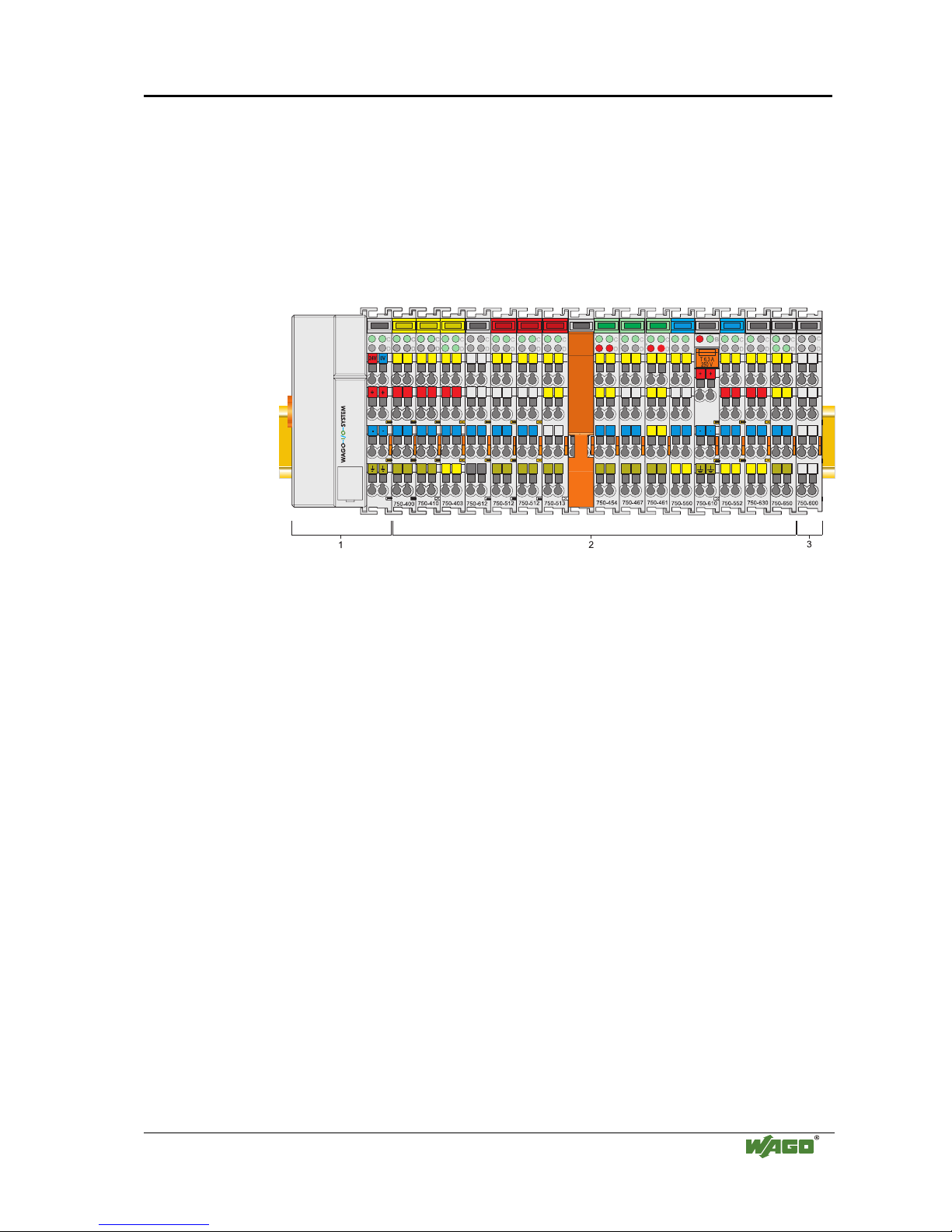
2 The WAGO-I/O-SYSTEM 750
2.1 System Description
The WAGO-I/O-SYSTEM 750 is a modular, fieldbus independent I/O system.
It is comprised of a fieldbus coupler/controller (1) and up to 64 connected
fieldbus modules (2) for any type of signal. Together, these make up the
fieldbus node. The end module (3) completes the node.
Fig. 2-1: Fieldbus node
g0xxx00x
Couplers / controllers for fieldbus systems such as PROFIBUS, INTERBUS,
ETHERNET TCP/IP, CAN (CANopen, DeviceNet, CAL), MODBUS, LON
and others are available.
The coupler / controller contains the fieldbus interface, electronics and a
power supply terminal. The fieldbus interface forms the physical interface to
the relevant fieldbus. The electronics process the data of the bus modules and
make it available for the fieldbus communication. The 24 V system supply and
the 24 V field supply are fed in via the integrated power supply terminal.
The fieldbus coupler communicates via the relevant fieldbus. The
programmable fieldbus controller (PFC) enables the implementation of
additional PLC functions. Programming is done with the WAGO-I/O-PRO 32
in accordance with IEC 61131-3.
Bus modules for diverse digital and analog I/O functions as well as special
functions can be connected to the coupler / controller. The communication
between the coupler/controller and the bus modules is carried out via an
internal bus.
The WAGO-I/O-SYSTEM 750 has a clear port level with LEDs for status
indication, insertable mini WSB markers and pullout group marker carriers.
The 3-wire technology supplemented by a ground wire connection allows for
direct sensor/actuator wiring.
6 • The WAGO-I/O-SYSTEM 750
Technical Data
WAGO-I/O-SYSTEM 750
ETHERNET TCP/IP
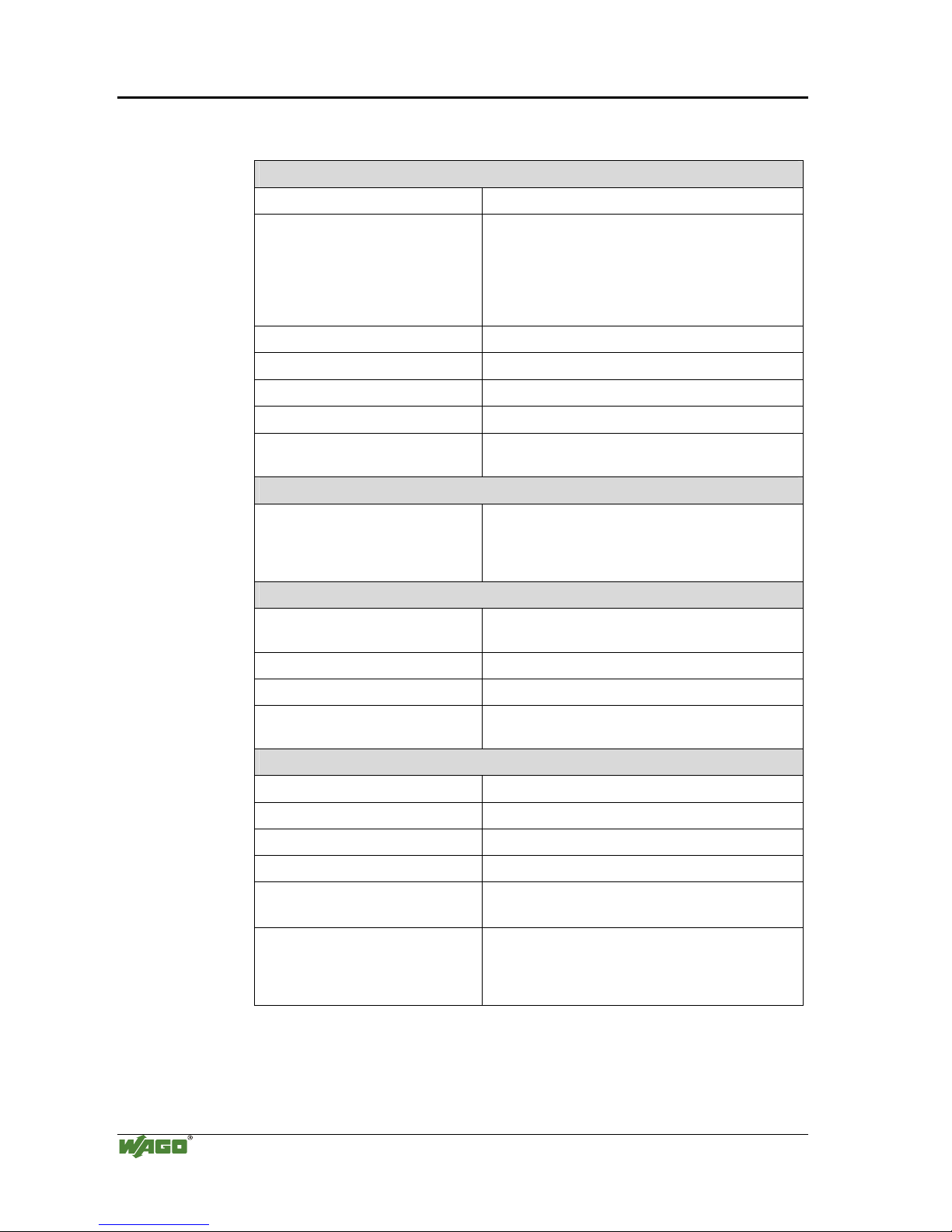
2.2 Technical Data
Mechanic
Material Polycarbonate, Polyamide 6.6
Dimensions
- Coupler / Controller
- I/O module, single
- I/O module, double
- 51 mm x 65* mm x 100 mm
- 12 mm x 64* mm x 100 mm
- 24 mm x 64* mm x 100 mm
* from upper edge of DIN 35 rail
Installation on DIN 35 with interlock
modular by double featherkey-dovetail
Mounting position any position
Length of entire node
≤ 831 mm
Marking marking label type 247 and 248
paper marking label 8 x 47 mm
Wire range
Wire range CAGE CLAMP® Connection
0,08 mm² ... 2.5 mm²
AWG 28-14
8 – 9 mm Stripped length
Contacts
Power jumpers contacts blade/spring contact
self-cleaning
Current via power contacts
max
10 A
Voltage drop at I
max
< 1 V/64 modules
Data contacts slide contact, hard gold plated
1,5µm, self-cleaning
Climatic environmental conditions
Operating temperature 0 °C ... 55 °C
Storage temperature -20 °C ... +85 °C
Relative humidity 5% to 95 % without condensation
Resistance to harmful substances acc. To IEC 60068-2-42 and IEC 60068-2-43
Maximum pollutant concentration at
relative humidity < 75%
SO
2
≤ 25 ppm
H
2
S ≤ 10 ppm
Special conditions Ensure that additional measures for components are
taken, which are used in an environment involving:
– dust, caustic vapors or gasses
– ionization radiation.
The WAGO-I/O-SYSTEM 750 • 7
Technical Data
WAGO-I/O-SYSTEM 750
ETHERNET TCP/IP
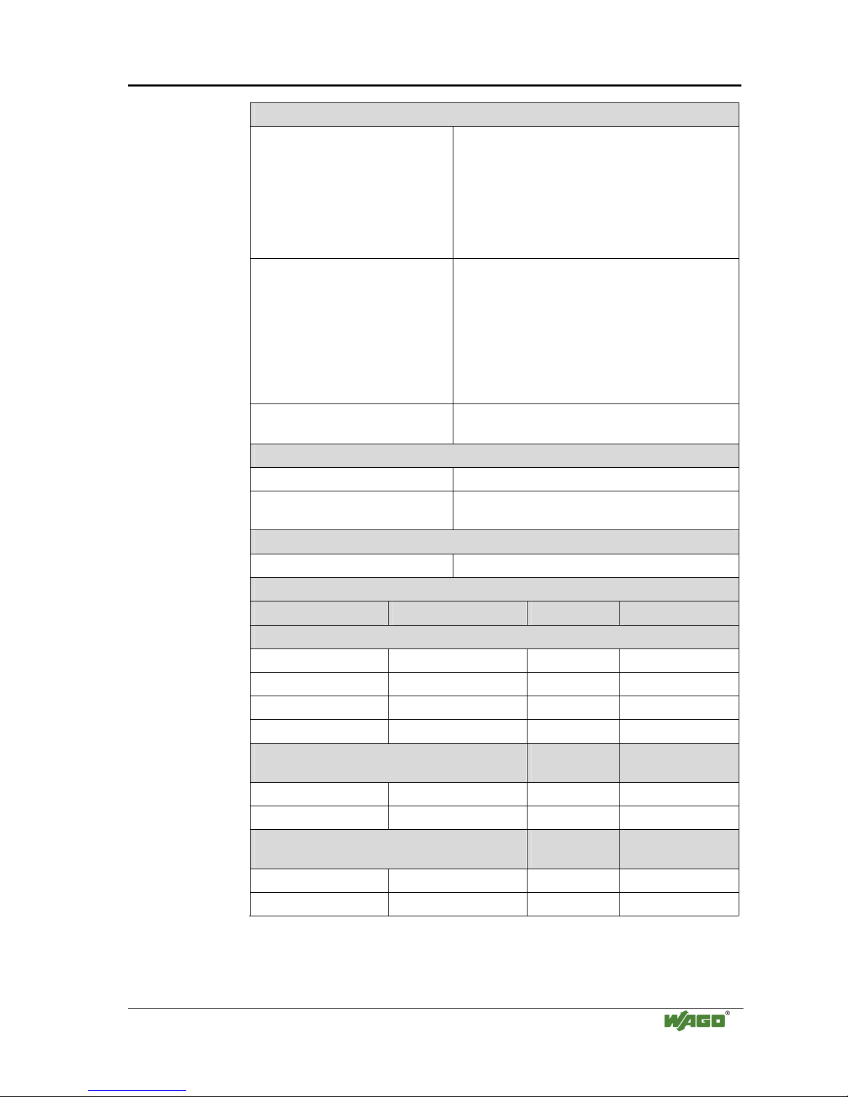
Mechanical strength
Vibration resistance acc. to IEC 60068-2-6
Comment to the vibration restistance:
a) Type of oscillation:
sweep with a rate of change of 1 octave per minute
10 Hz ≤ f < 57 Hz, const. Amplitude 0,075 mm
57 Hz ≤ f < 150 Hz, const. Acceleration 1 g
b) Period of oscillation:
10 sweep per axis in each of the 3 vertical axes
Shock resistance acc. to IEC 60068-2-27
Comment to the shock restistance:
a) Type of impulse: half sinusoidal
b) Intensity of impulse:
15 g peak value, 11 ms maintenance time
c) Route of impulse:
3 impulses in each pos. And neg. direction of the
3 vertical axes of the test object, this means
18 impulses in all
Free fall acc. to IEC 60068-2-32
≤ 1m (module in original packing)
Safe electrical isolation
Air and creepage distance acc. to IEC 60664-1
Degree of pollution
acc. To IEC 61131-2
2
Degree of protection
Degree of protection IP 20
Electromagnetic compatibility*
Directive Test values Strength class Evaluation criteria
Immunity to interference acc. to EN 50082-2 (96)
EN 61000-4-2 4kV/8kV (2/4) B
EN 61000-4-3 10V/m 80% AM (3) A
EN 61000-4-4 2kV (3/4) B
EN 61000-4-6 10V/m 80% AM (3) A
Emission of interference acc. to
EN 50081-2 (94)
Measuring
distance
Class
EN 55011 30 dBµV/m (30m) A
37 dBµV/m
Emission of interference acc. to
EN 50081-1 (93)
Measuring
distance
Class
EN 55022 30 dBµV/m (10m) B
37 dBµV/m
* Exception: 750-630, 750-631
8 • The WAGO-I/O-SYSTEM 750
Technical Data
WAGO-I/O-SYSTEM 750
ETHERNET TCP/IP
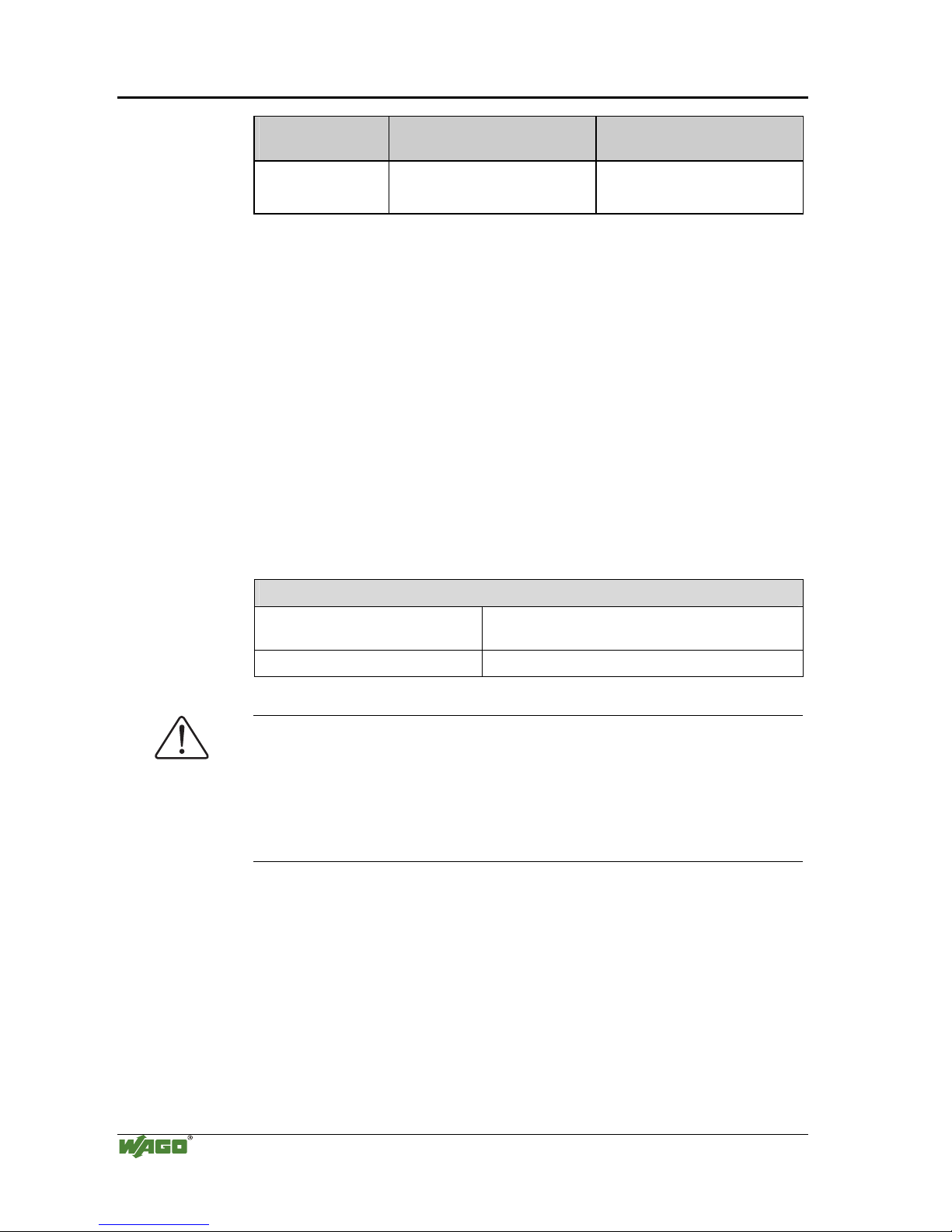
Range of
application
Required specification
emission of interference
Required specification
immunity to interference
Industrial areas EN 50081-2 : 1993 EN 50082-2 : 1996
Residential areas EN 50081-1 : 1993*) EN 50082-1 : 1992
*)
The system meets the requirements on emission of interference in residential areas with
the fieldbus coupler/controller for:
ETHERNET
LonWorks
CANopen
DeviceNet
MODBUS
750-342/-841/-842
750-319/-819
750-337/-837
750-306/-806
750-312/-314/ -315/ -316
750-812/-814/ -815/ -816
With a special permit, the system can also be implemented with other fieldbus
couplers/controllers in residential areas (housing, commercial and business areas, smallscale enterprises). The special permit can be obtained from an authority or inspection
office. In Germany, the Federal Office for Post and Telecommunications and its branch
offices issues the permit.
It is possible to use other field bus couplers / controllers under certain boundary
conditions. Please contact WAGO Kontakttechnik GmbH.
Maximum power dissipation of the components
Bus modules 0.8 W / bus terminal (total power dissipation,
system/field)
Fieldbus coupler / controller 2.0 W / coupler / controller
Warning
The power dissipation of all installed components must not exceed the
maximum conductible power of the housing (cabinet).
When dimensioning the housing, care is to be taken that even under high
external temperatures, the temperature inside the housing does not exceed the
permissible ambient temperature of 55 °C.
The WAGO-I/O-SYSTEM 750 • 9
Manufacturing Number
WAGO-I/O-SYSTEM 750
ETHERNET TCP/IP
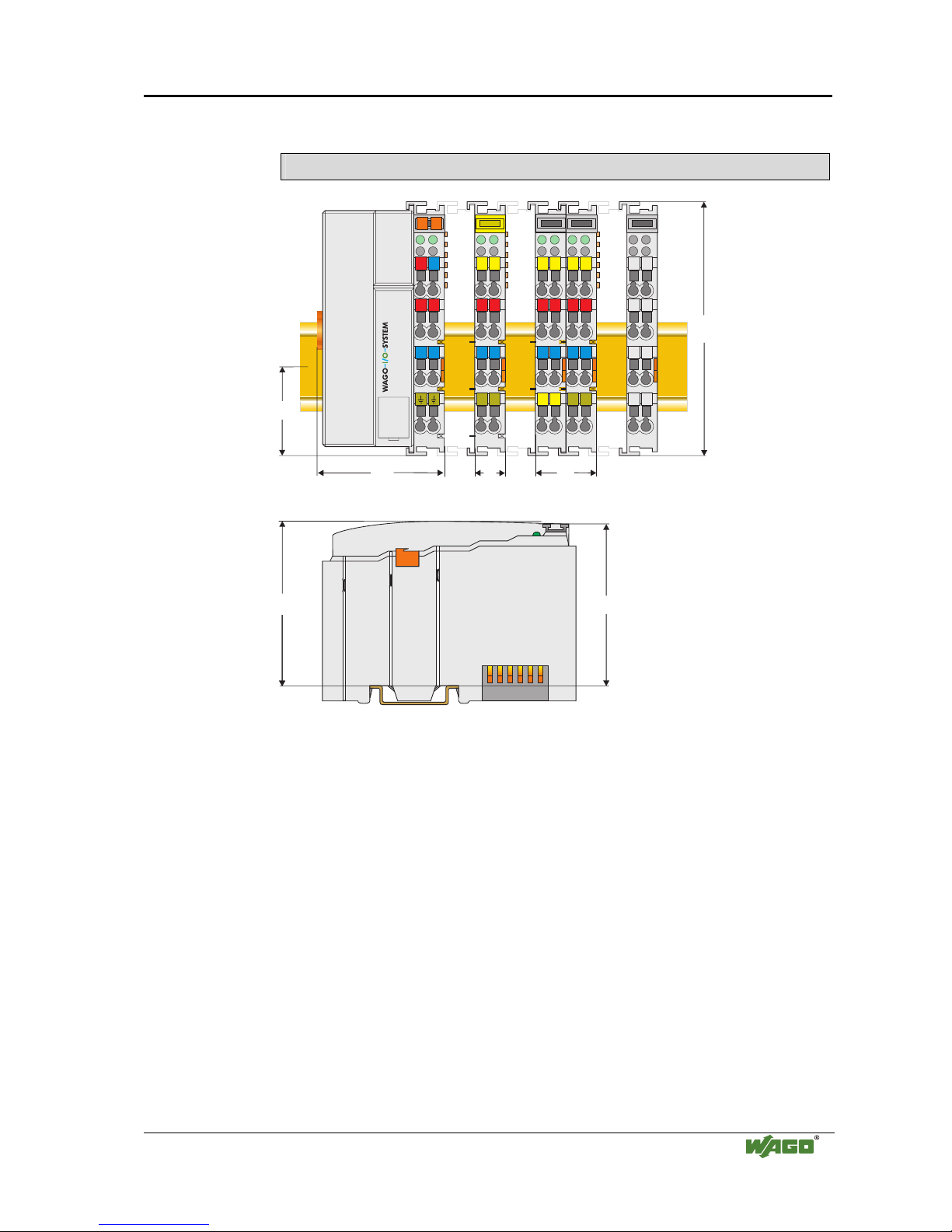
Dimensions
51
24V 0V
+
+
-
-
01
02
C
D
B
A
C
D
B
A
C
D
B
A
C
D
B
A
C
D
B
A
100
12
24
64
35
65
Side view
Dimensions in mm
Fig. 2-2: Dimensions
g01xx05e
2.3 Manufacturing Number
The manufacturing number indicates the delivery status directly after
production.
This number is part of the lateral marking on the component.
In addition, starting from calender week 43/2000 the manufacturing number is
also printed on the cover of the configuration and programming interface of
the fieldbus coupler or controller.
10 • The WAGO-I/O-SYSTEM 750
Component Update
WAGO-I/O-SYSTEM 750
ETHERNET TCP/IP
Hansastr. 27
D-32423 Minden
ITEM-NO.:750-333
PROFIBUS DP 12 MBd /DPV1
0V
Power Supply
Electronic
PATENTS PENDING
II 3 GD
DEMKO 02 ATEX132273 X
EEx nA II T4
24V DC
AWG 28-14
55°C max ambient
LISTED 22ZAAND 22XM
72072
0103000203-B000000
Hansastr. 27
D-32423 Minden
ITEM-NO.:750-333
PROFIBUS DP 12 MBd /DPV1
0V
Power Supply
Electronic
PATENTS PENDING
II 3 GD
DEMKO 02 ATEX132273 X
EEx nA II T4
24V DC
AWG 28-14
55°C max ambient
LISTED 22ZAAND 22XM
72072
0103000203-B000000
1
0
3
0
0
0
2
0
0
3
DS
NO
SW
HW
GL
FWL
Power Supply
Field
24 V
+
-
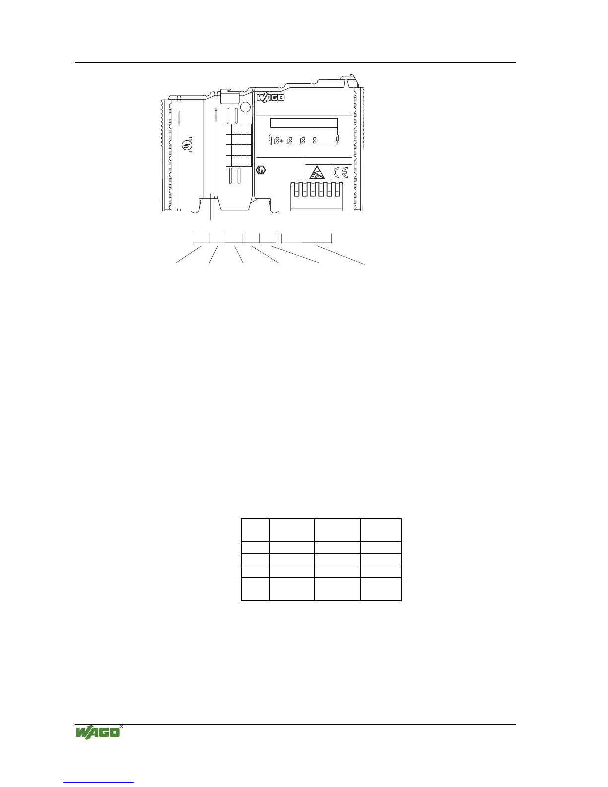
-B000000
Manufacturing Number
Calendar
week
Year Software
version
Hardware
version
Firmware-loader
version
Internal
Number
Fig. 2-3: Example: Manufacturing Number of a PROFIBUS fieldbus coupler 750-333
g01xx15e
The manufacturing number consists of the production week and year, the
software version (if available), the hardware version of the component, the
firmware loader (if available) and further internal information for
WAGO Kontakttechnik GmbH.
2.4 Component Update
For the case of an Update of one component, the lateral marking on each
component contains a prepared matrix.
This matrix makes columns available for altogether three updates to the entry
of the current update data, like production order number (NO; starting from
calendar week 13/2004), update date (DS), software version (SW), hardware
version (HW) and the firmware loader version (FWL, if available).
Update Matrix
Current Version data for: 1. Update 2. Update 3. Update
Production Order
Number
NO
<- Only starting from
Calendar week 13/2004
Datestamp
DS
Software index
SW
Hardware index
HW
Firmware loader
index
FWL
<- Only for coupler/controller
If the update of a component took place, the current version data are registered
into the columns of the matrix.
Additionally with the update of a fieldbus coupler or controller also the cover
of the configuration and programming interface of the coupler or controller is
printed on with the current manufacturing and production order number.
The original manufacturing data on the housing of the component remain
thereby.
The WAGO-I/O-SYSTEM 750 • 11
Storage, Assembly and Transport
WAGO-I/O-SYSTEM 750
ETHERNET TCP/IP
2.5 Storage, Assembly and Transport
Wherever possible, the components are to be stored in their original
packaging. Likewise, the original packaging provides optimal protection
during transport.
When assembling or repacking the components, the contacts must not be
soiled or damaged. The components must be stored and transported in
appropriate containers/packaging. Thereby, the ESD information is to be
regarded.
Statically shielded transport bags with metal coatings are to be used for the
transport of open components for which soiling with amine, amide and
silicone has been ruled out, e.g. 3M 1900E.
2.6 Mechanical Setup
2.6.1 Installation Position
Along with horizontal and vertical installation, all other installation positions
are allowed.
Attention
In the case of vertical assembly, an end stop has to be mounted as an
additional safeguard against slipping.
WAGO item 249-116 End stop for DIN 35 rail, 6 mm wide
WAGO item 249-117 End stop for DIN 35 rail, 10 mm wide
2.6.2 Total Expansion
The maximum total expansion of a node is calculated as follows:
Quantity Width Components
1 51 mm coupler / controller
64 12 mm bus modules
- inputs / outputs
- power supply modules
- etc.
1 12 mm end module
sum 831 mm
Warning
The maximal total expansion of a node must not exceed 831 mm
12 • The WAGO-I/O-SYSTEM 750
Mechanical Setup
WAGO-I/O-SYSTEM 750
ETHERNET TCP/IP
2.6.3 Assembly onto Carrier Rail
2.6.3.1 Carrier rail properties
All system components can be snapped directly onto a carrier rail in
accordance with the European standard EN 50022 (DIN 35).
Warning
WAGO supplies standardized carrier rails that are optimal for use with the
I/O system. If other carrier rails are used, then a technical inspection and
approval of the rail by WAGO Kontakttechnik GmbH should take place.
Carrier rails have different mechanical and electrical properties. For the
optimal system setup on a carrier rail, certain guidelines must be observed:
• The material must be non-corrosive.
• Most components have a contact to the carrier rail to ground electro-
magnetic disturbances. In order to avoid corrosion, this tin-plated carrier
rail contact must not form a galvanic cell with the material of the carrier
rail which generates a differential voltage above 0.5 V (saline solution of
0.3% at 20°C) .
• The carrier rail must optimally support the EMC measures integrated into
the system and the shielding of the bus module connections.
• A sufficiently stable carrier rail should be selected and, if necessary,
several mounting points (every 20 cm) should be used in order to prevent
bending and twisting (torsion).
• The geometry of the carrier rail must not be altered in order to secure the
safe hold of the components. In particular, when shortening or mounting
the carrier rail, it must not be crushed or bent.
• The base of the I/O components extends into the profile of the carrier rail.
For carrier rails with a height of 7.5 mm, mounting points are to be riveted
under the node in the carrier rail (slotted head captive screws or blind
rivets).
The WAGO-I/O-SYSTEM 750 • 13
Mechanical Setup
WAGO-I/O-SYSTEM 750
ETHERNET TCP/IP
2.6.3.2 WAGO DIN Rail
WAGO carrier rails meet the electrical and mechanical requirements.
Item Number Description
210-113 /-112 35 x 7.5; 1 mm; steel yellow chromated; slotted/unslotted
210-114 /-197 35 x 15; 1.5 mm; steel yellow chromated; slotted/unslotted
210-118 35 x 15; 2.3 mm; steel yellow chromated; unslotted
210-198 35 x 15; 2.3 mm; copper; unslotted
210-196 35 x 7.5; 1 mm; aluminum; unslotted
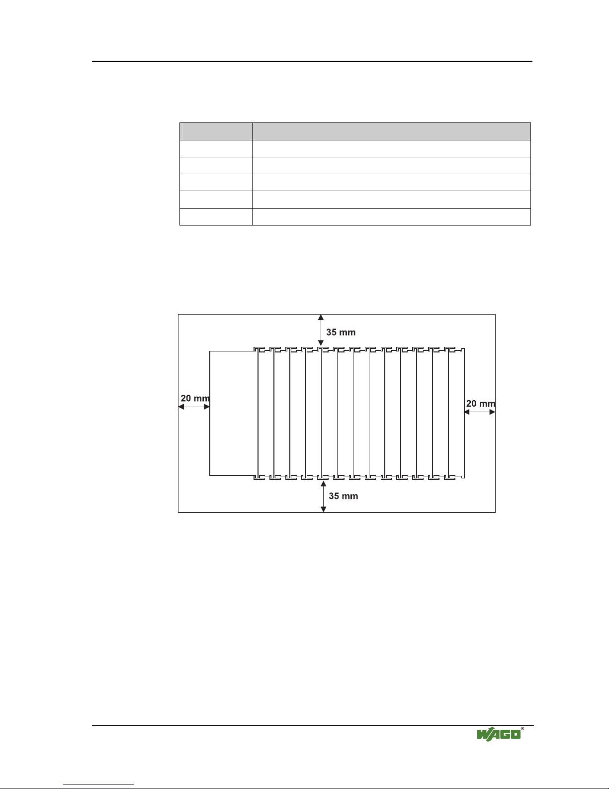
2.6.4 Spacing
The spacing between adjacent components, cable conduits, casing and frame
sides must be maintained for the complete field bus node.
Fig. 2-4: Spacing
g01xx13x
The spacing creates room for heat transfer, installation or wiring. The spacing
to cable conduits also prevents conducted electromagnetic interferences from
influencing the operation.
14 • The WAGO-I/O-SYSTEM 750
Mechanical Setup
WAGO-I/O-SYSTEM 750
ETHERNET TCP/IP
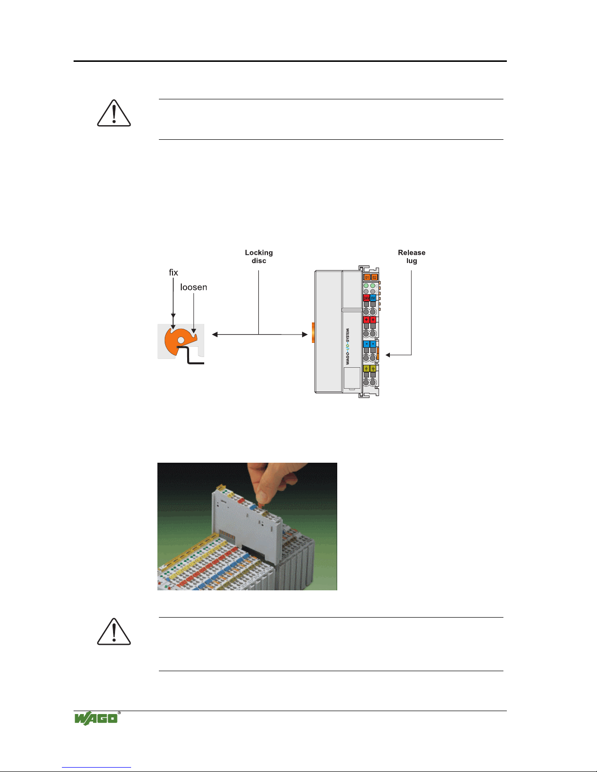
2.6.5 Plugging and Removal of the Components
Warning
Before work is done on the components, the voltage supply must be turned
off.
In order to safeguard the coupler/controller from jamming, it should be fixed
onto the carrier rail with the locking disc To do so, push on the upper groove
of the locking disc using a screwdriver.
To pull out the fieldbus coupler/controller, release the locking disc by pressing
on the bottom groove with a screwdriver and then pulling the orange colored
unlocking lug.
Fig. 2-5: Coupler/Controller and unlocking lug
g01xx12e
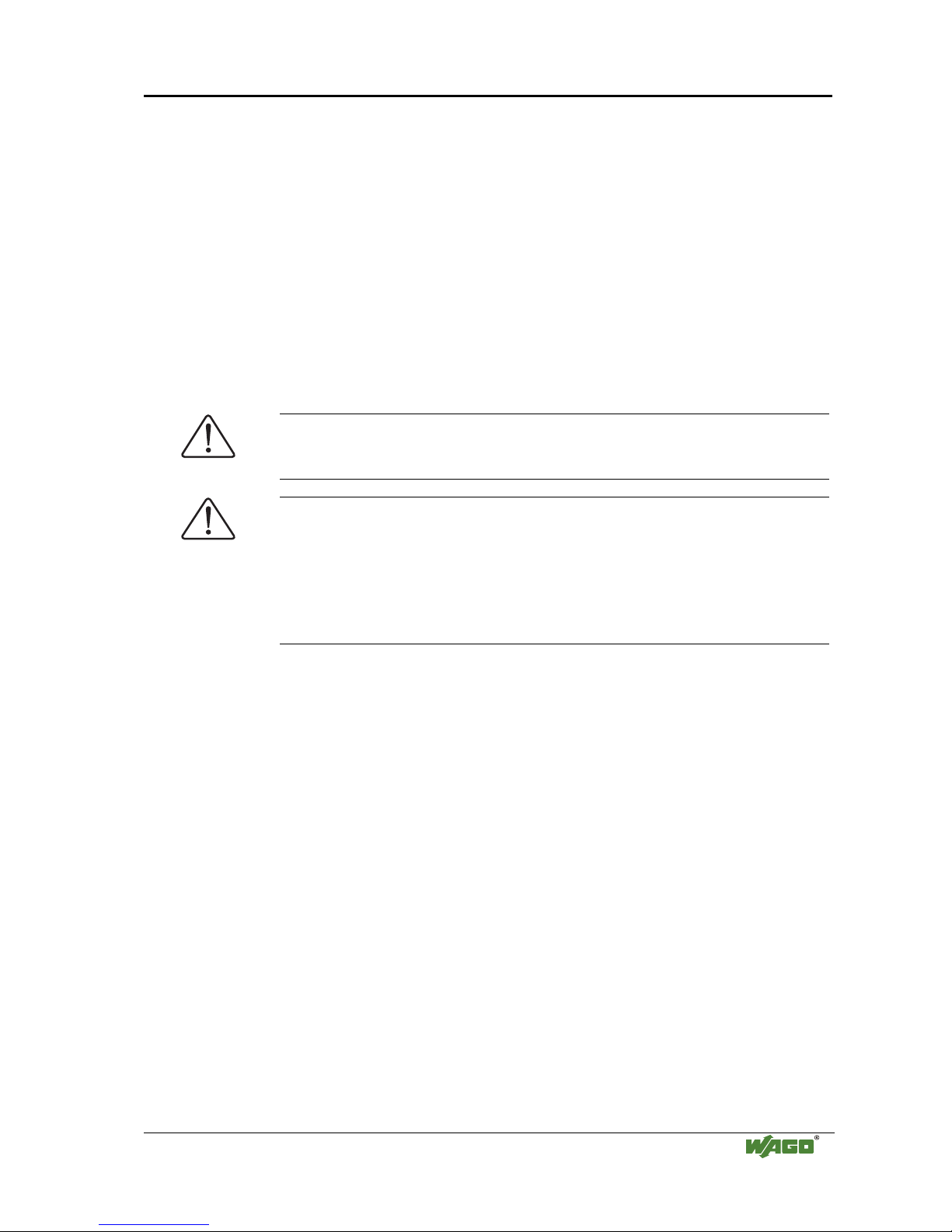
It is also possible to release an individual I/O module from the unit by pulling
an unlocking lug.
Fig. 2-6: removing bus terminal
p0xxx01x
Danger
Ensure that an interruption of the PE will not result in a condition which
could endanger a person or equipment!
For planning the ring feeding of the ground wire, please see chapter 2.6.3.
The WAGO-I/O-SYSTEM 750 • 15
Mechanical Setup
WAGO-I/O-SYSTEM 750
ETHERNET TCP/IP
2.6.6 Assembly Sequence
All system components can be snapped directly on a carrier rail in accordance
with the European standard EN 50022 (DIN 35).
The reliable positioning and connection is made using a tongue and groove
system. Due to the automatic locking, the individual components are securely
seated on the rail after installing.
Starting with the coupler/controller, the bus modules are assembled adjacent
to each other according to the project planning. Errors in the planning of the
node in terms of the potential groups (connection via the power contacts) are
recognized, as the bus modules with power contacts (male contacts) cannot be
linked to bus modules with fewer power contacts.
Attention
Always link the bus modules with the coupler / controller, and always plug
from above.
Warning
Never plug bus modules from the direction of the end terminal. A ground
wire power contact, which is inserted into a terminal without contacts, e.g. a
4-channel digital input module, has a decreased air and creepage distance to
the neighboring contact in the example DI4.
Always terminate the fieldbus node with an end module (750-600).
16 • The WAGO-I/O-SYSTEM 750
Mechanical Setup
WAGO-I/O-SYSTEM 750
ETHERNET TCP/IP
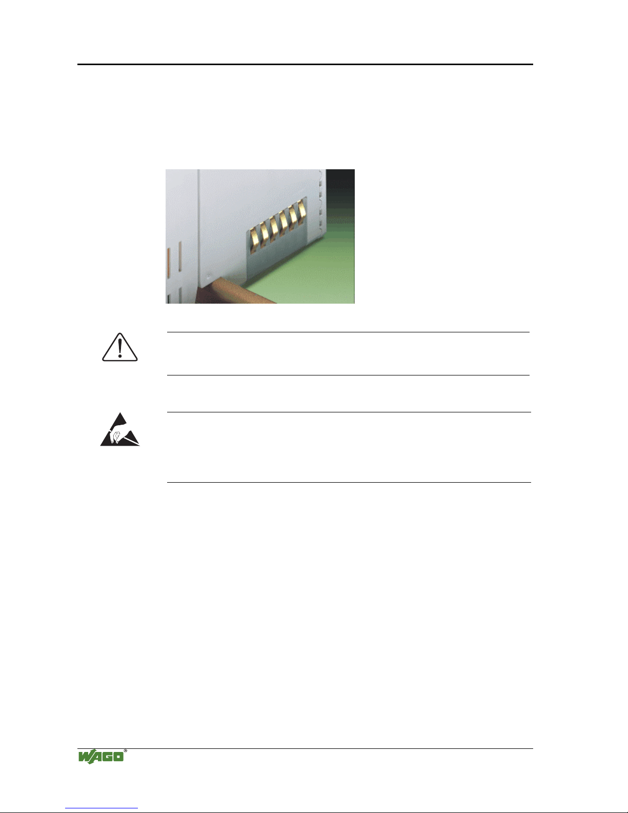
2.6.7 Internal Bus / Data Contacts
Communication between the coupler/controller and the bus modules as well as
the system supply of the bus modules is carried out via the internal bus. It is
comprised of 6 data contacts, which are available as self-cleaning gold spring
contacts.
Fig. 2-7: Data contacts
p0xxx07x
Warning
Do not touch the gold spring contacts on the I/O modules in order to avoid
soiling or scratching!
ESD (Electrostatic Discharge)
The modules are equipped with electronic components that may be destroyed
by electrostatic discharge. When handling the modules, ensure that the
environment (persons, workplace and packing) is well grounded. Avoid
touching conductive components, e.g. gold contacts.
The WAGO-I/O-SYSTEM 750 • 17
Mechanical Setup
WAGO-I/O-SYSTEM 750
ETHERNET TCP/IP
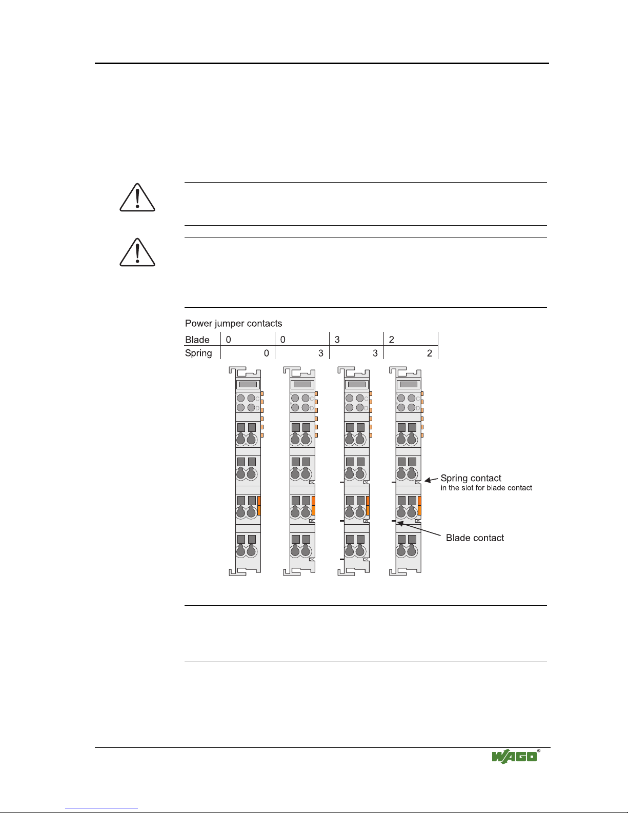
2.6.8 Power Contacts
Self-cleaning power contacts , are situated on the side of the components
which further conduct the supply voltage for the field side. These contacts
come as touchproof spring contacts on the right side of the coupler/controller
and the bus module. As fitting counterparts the module has male contacts on
the left side.
Danger
The power contacts are sharp-edged. Handle the module carefully to prevent
injury.
Attention
Please take into consideration that some bus modules have no or only a few
power jumper contacts. The design of some modules does not allow them to
be physically assembled in rows, as the grooves for the male contacts are
closed at the top.
Fig. 2-8: Example for the arrangement of power contacts
g0xxx05e
Recommendation
With the WAGO ProServe® Software smartDESIGNER, the assembly of a
fieldbus node can be configured. The configuration can be tested via the
integrated accuracy check.
18 • The WAGO-I/O-SYSTEM 750
Mechanical Setup
WAGO-I/O-SYSTEM 750
ETHERNET TCP/IP
2.6.9 Wire connection
All components have CAGE CLAMP® connections.
The WAGO CAGE CLAMP® connection is appropriate for solid, stranded
and fine–stranded conductors. Each clamping unit accommodates one
conductor.
Fig. 2-9: CAGE CLAMP® Connection
g0xxx08x
The operating tool is inserted into the opening above the connection. This
opens the CAGE CLAMP®. Subsequently the conductor can be inserted into
the opening. After removing the operating tool, the conductor is safely
clamped.
More than one conductor per connection is not permissible. If several
conductors have to be made at one connection point, then they should be made
away from the connection point using WAGO Terminal Blocks. The terminal
blocks may be jumpered together and a single wire brought back to the I/O
module connection point.
Attention
If it is unavoidable to jointly connect 2 conductors, then a ferrule must be
used to join the wires together.
Ferrule:
Length 8 mm
Nominal cross section
max.
1 mm2 for 2 conductors with 0.5 mm2
each
WAGO Product 216-103
or products with comparable properties
The WAGO-I/O-SYSTEM 750 • 19
Power Supply
WAGO-I/O-SYSTEM 750
ETHERNET TCP/IP
2.7 Power Supply
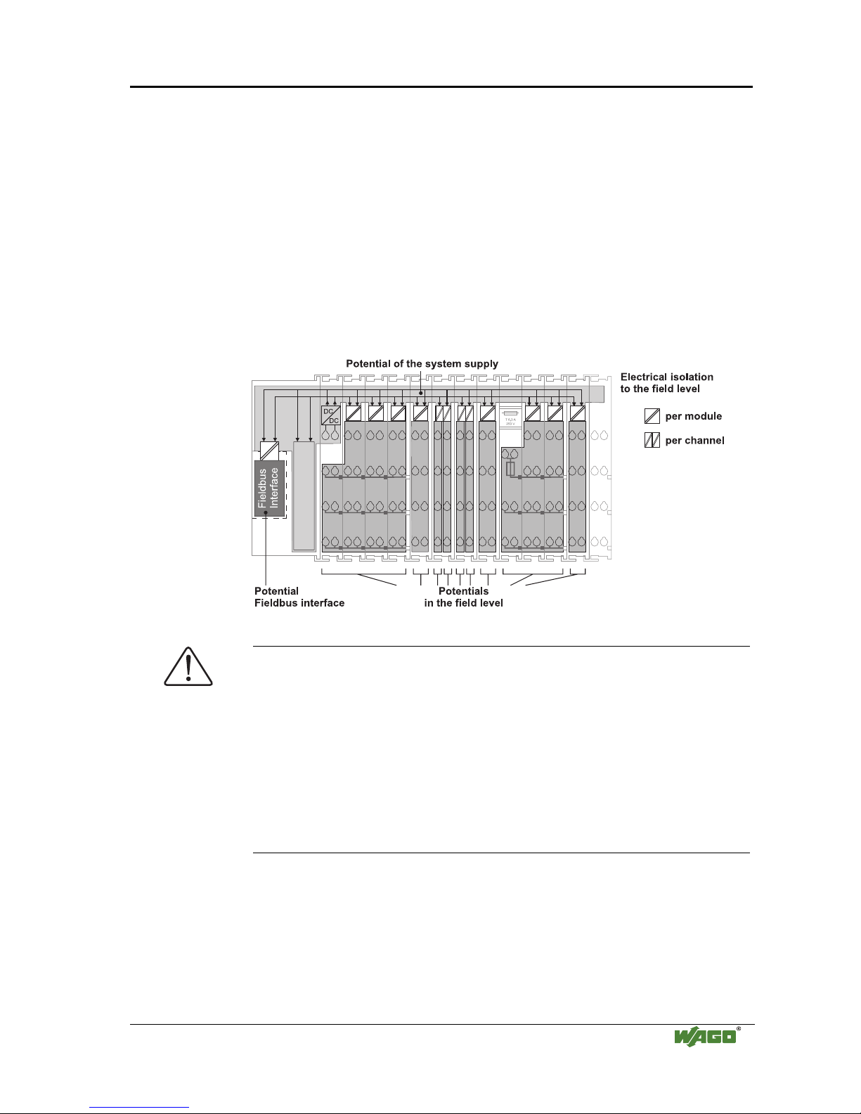
2.7.1 Isolation
Within the fieldbus node, there are three electrically isolated potentials.
• Operational voltage for the fieldbus interface.
• Electronics of the couplers / controllers and the bus modules (internal bus).
• All bus modules have an electrical isolation between the electronics
(internal bus, logic) and the field electronics. Some digital and analog
input modules have each channel electrically isolated, please see catalog.
Fig. 2-10: Isolation
g0xxx01e
Attention
The ground wire connection must be present in each group. In order that all
protective conductor functions are maintained under all circumstances, it is
recommended that a ground wire be connected at the beginning and end of a
potential group. (ring format, please see chapter "2.8.3"). Thus, if a bus
module comes loose from a composite during servicing, then the protective
conductor connection is still guaranteed for all connected field devices.
When using a joint power supply unit for the 24 V system supply and the
24 V field supply, the electrical isolation between the internal bus and the
field level is eliminated for the potential group.
20 • The WAGO-I/O-SYSTEM 750
Power Supply
WAGO-I/O-SYSTEM 750
ETHERNET TCP/IP
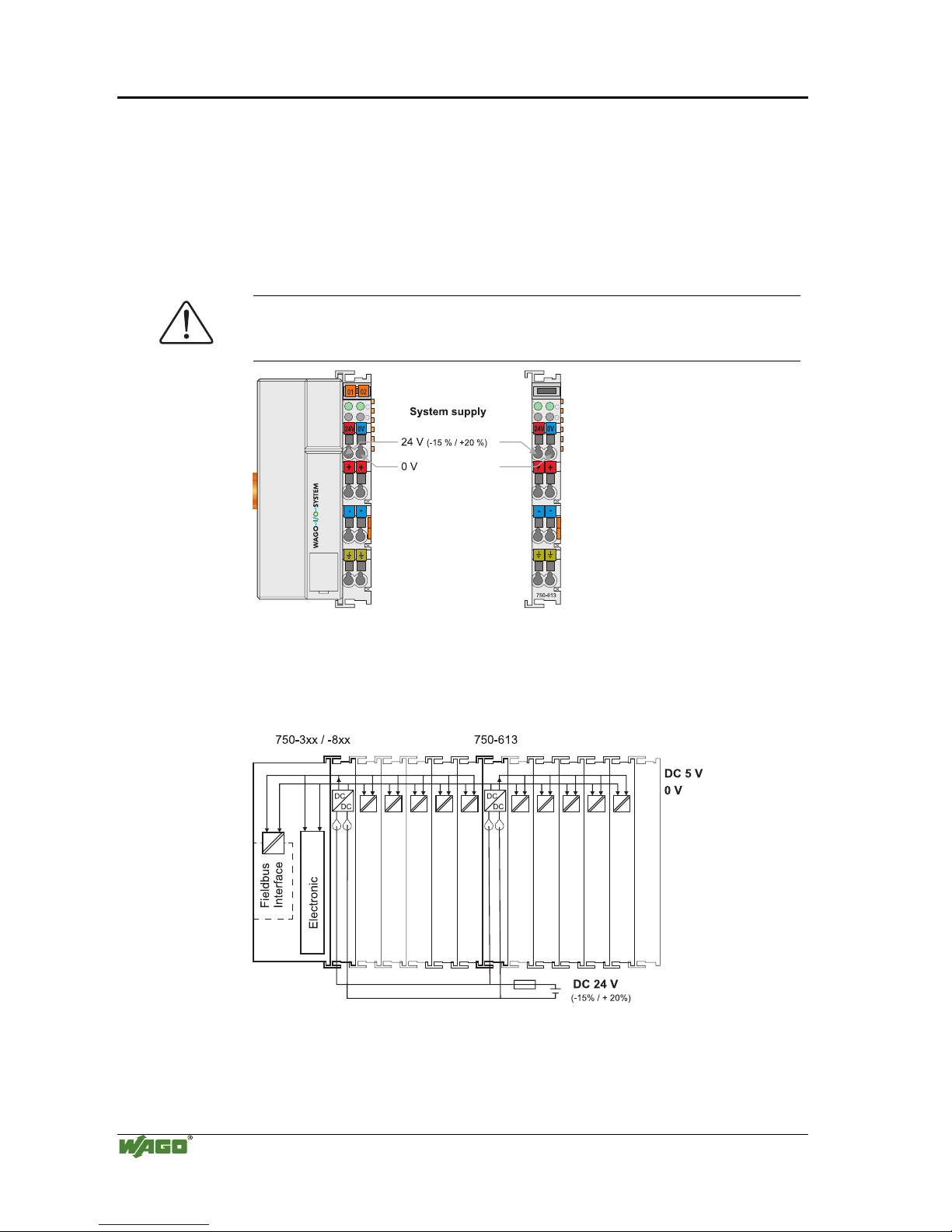
2.7.2 System Supply
2.7.2.1 Connection
The WAGO-I/O-SYSTEM 750 requires a 24 V direct current system supply
(-15% or +20 %). The power supply is provided via the coupler / controller
and, if necessary, in addition via the internal system supply modules
(750-613). The voltage supply is reverse voltage protected.
Attention
The use of an incorrect supply voltage or frequency can cause severe damage
to the component.
Fig. 2-11: System Supply
g0xxx02e
The direct current supplies all internal system components, e.g.
coupler/controller electronics, fieldbus interface and bus modules via the
internal bus (5 V system voltage). The 5 V system voltage is electrically
connected to the 24 V system supply.
Fig. 2-12: System Voltage g0xxx06e
The WAGO-I/O-SYSTEM 750 • 21
Power Supply
WAGO-I/O-SYSTEM 750
ETHERNET TCP/IP
Attention
Resetting the system by switching on and off the system supply, must take
place simultaneously for all supply modules (coupler / controller and
750-613).
2.7.2.2 Alignment
Recommendation
A stable network supply cannot be taken for granted always and everywhere.
Therefore, regulated power supply units should be used in order to guarantee
the quality of the supply voltage.
The supply capacity of the coupler/controller or the internal system supply
module (750-613) can be taken from the technical data of the components.
Internal current consumption*)
Current consumption via system voltage:
5 V for electronics of the bus modules and coupler /
controller
Residual current for bus
terminals*)
Available current for the bus modules. Provided by
the bus power supply unit. See coupler / controller
and internal system supply module (750-613)
*) cf. catalogue W4 Volume 3, manuals or Internet
Example
Coupler 750-301:
internal current consumption:350 mA at 5V
residual current for
bus modules : 1650 mA at 5V
sum I(5V)
total
: 2000 mA at 5V
The internal current consumption is indicated in the technical data for each
bus terminal. In order to determine the overall requirement, add together the
values of all bus modules in the node.
Attention
If the sum of the internal current consumption exceeds the residual current
for bus modules, then an internal system supply module (750-613) must be
placed before the module where the permissible residual current was
exceeded.
Example:
A node with a PROFIBUS Coupler 750-333 consists of 20 relay
modules (750-517) and 10 digital input modules (750-405).
Current consumption:
20* 90 mA = 1800 mA
10* 2 mA = 20 mA
Sum 1820 mA
The coupler can provide 1650 mA for the bus modules. Consequently,
an internal system supply module (750-613), e.g. in the middle of the
node, should be added.
22 • The WAGO-I/O-SYSTEM 750
Power Supply
WAGO-I/O-SYSTEM 750
ETHERNET TCP/IP
Recommendation
With the WAGO ProServe® Software smartDESIGNER, the assembly of a
fieldbus node can be configured. The configuration can be tested via the
integrated accuracy check.
The maximum input current of the 24 V system supply is 500 mA. The exact
electrical consumption (I
(24 V)
) can be determined with the following formulas:
Coupler/Controller
I(5 V)
total
= Sum of all the internal current consumption of the connected
bus modules
+ internal current consumption coupler / controller
750-613
I(5 V)
total
= Sum of all the internal current consumption of the connected
bus modules
Input current I(24 V) =
5 V / 24 V * I(5 V)
total
/ η
η = 0.87 (at nominal load)
Note
If the electrical consumption of the power supply point for the 24 V-system
supply exceeds 500 mA, then the cause may be an improperly aligned node
or a defect.
During the test, all outputs, in particular those of the relay modules, must be
active.
The WAGO-I/O-SYSTEM 750 • 23
Power Supply
WAGO-I/O-SYSTEM 750
ETHERNET TCP/IP
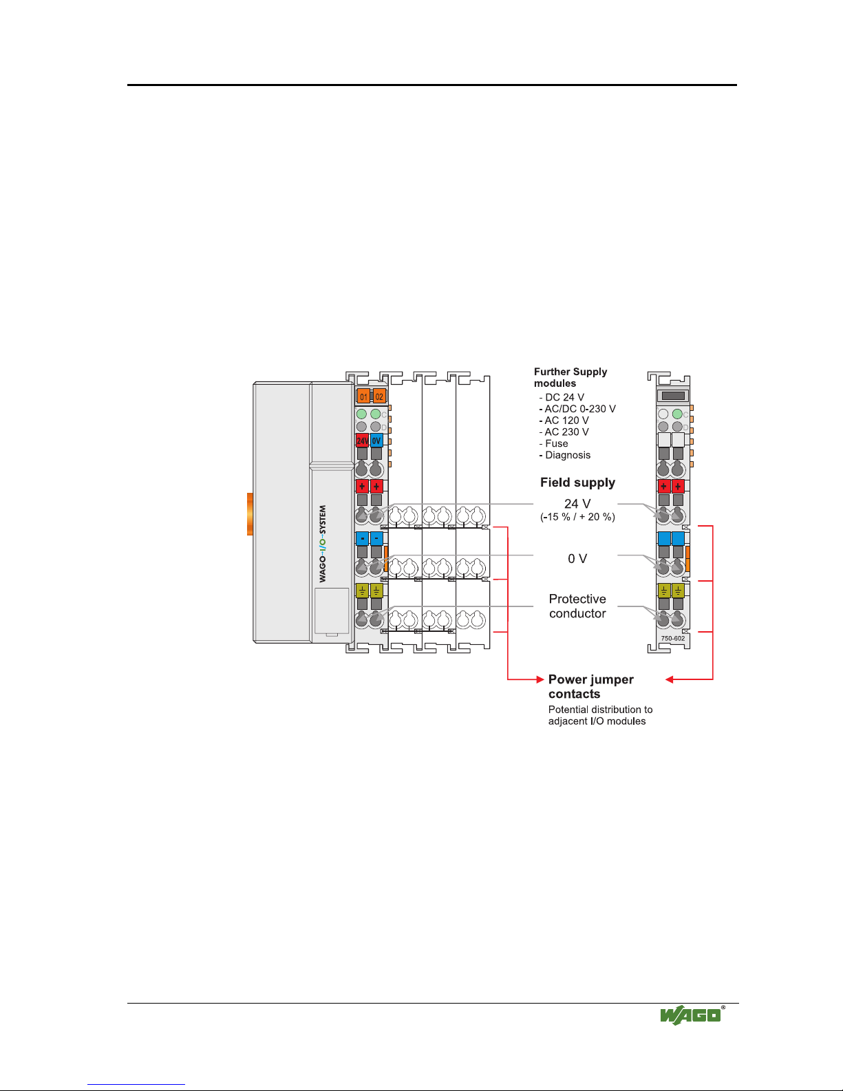
2.7.3 Field Supply
2.7.3.1 Connection
Sensors and actuators can be directly connected to the relevant channel of the
bus module in 1-/4 conductor connection technology. The bus module supplies
power to the sensors and actuators. The input and output drivers of some bus
modules require the field side supply voltage.
The coupler/controller provides field side power (DC 24V). In this case it is a
passive power supply without protection equipment.
Power supply modules are available for other potentials, e.g. AC 230 V.
Likewise, with the aid of the power supply modules, various potentials can be
set up. The connections are linked in pairs with a power contact.
Fig. 2-13: Field Supply (Sensor / Actuator)
g0xxx03e
The supply voltage for the field side is automatically passed to the next
module via the power jumper contacts when assembling the bus modules .
The current load of the power contacts must not exceed 10 A on a continual
basis. The current load capacity between two connection terminals is identical
to the load capacity of the connection wires.
By inserting an additional power supply module, the field supply via the
power contacts is disrupted. From there a new power supply occurs which
may also contain a new voltage potential.
24 • The WAGO-I/O-SYSTEM 750
Power Supply
WAGO-I/O-SYSTEM 750
ETHERNET TCP/IP
Attention
Some bus modules have no or very few power contacts (depending on the I/O
function). Due to this, the passing through of the relevant potential is
disrupted. If a field supply is required for subsequent bus modules, then a
power supply module must be used.
Note the data sheets of the bus modules.
In the case of a node setup with different potentials, e.g. the alteration from
DC 24 V to AC 230V, a spacer module should be used. The optical
separation of the potentials acts as a warning to heed caution in the case of
wiring and maintenance works. Thus, the results of wiring errors can be
prevented.
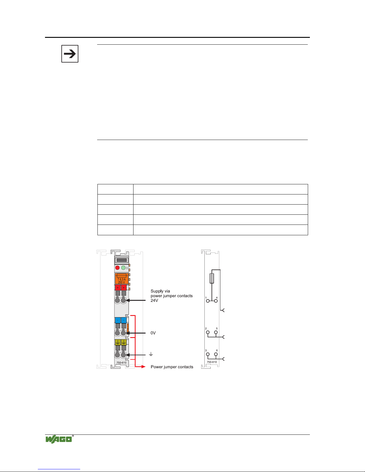
2.7.3.2 Fusing
Internal fusing of the field supply is possible for various field voltages via an
appropriate power supply module.
750-601 24 V DC, Supply / Fuse
750-609 230 V AC, Supply / Fuse
750-615 120 V AC, Supply / Fuse
750-610 24 V DC, Supply / Fuse / Diagnosis
750-611 230 V AC, Supply / Fuse / Diagnosis
Fig. 2-14: Supply module with fuse carrier (Example 750-610)
g0xxx09x
The WAGO-I/O-SYSTEM 750 • 25
Power Supply
WAGO-I/O-SYSTEM 750
ETHERNET TCP/IP
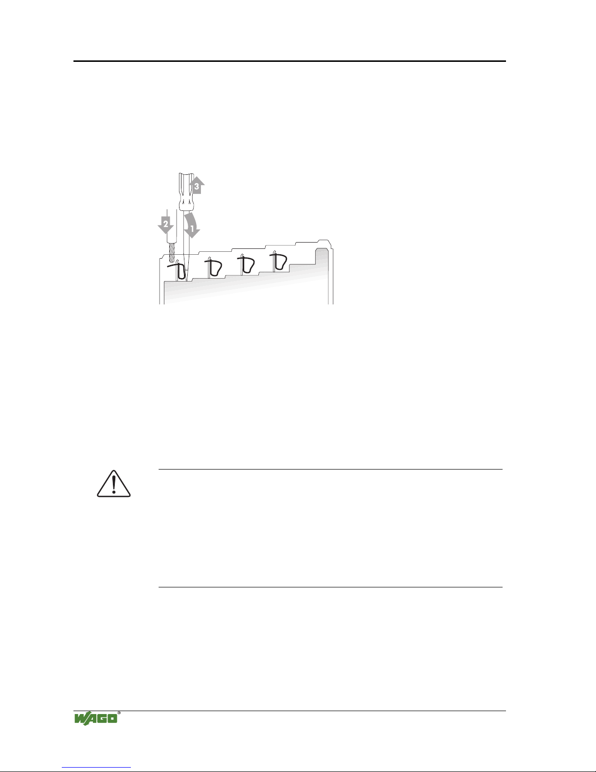
Warning
In the case of power supply modules with fuse holders, only fuses with a
maximum dissipation of 1.6 W (IEC 127) must be used.
For UL approved systems only use UL approved fuses.
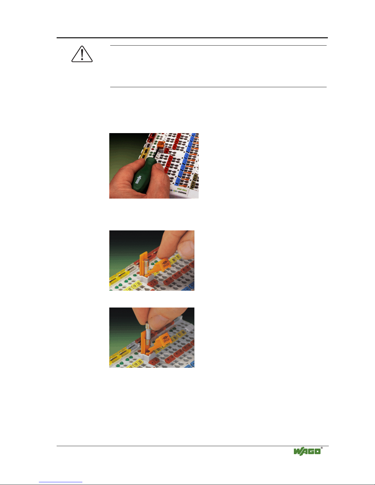
In order to insert or change a fuse, or to switch off the voltage in succeeding
bus modules, the fuse holder may be pulled out. In order to do this, use a
screwdriver for example, to reach into one of the slits (one on both sides) and
pull out the holder.
Fig. 2-15: Removing the fuse carrier
p0xxx05x
Lifting the cover to the side opens the fuse carrier.
Fig. 2-16: Opening the fuse carrier
p0xxx03x
Fig. 2-17: Change fuse
p0xxx04x
After changing the fuse, the fuse carrier is pushed back into its original
position.
26 • The WAGO-I/O-SYSTEM 750
Power Supply
WAGO-I/O-SYSTEM 750
ETHERNET TCP/IP
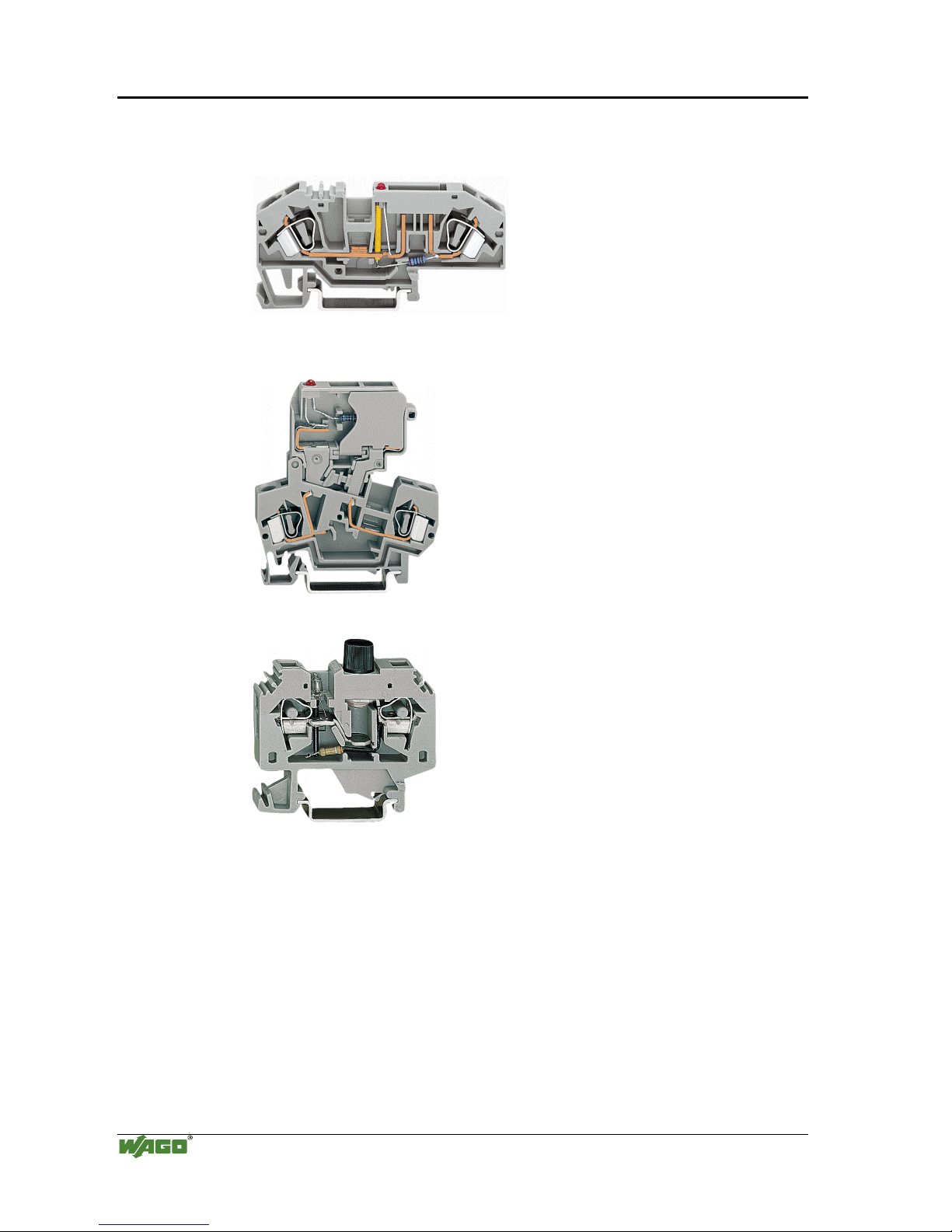
Alternatively, fusing can be done externally. The fuse modules of the WAGO
series 281 and 282 are suitable for this purpose.
Fig. 2-18: Fuse modules for automotive fuses, Series 282
pf66800x
Fig. 2-19: Fuse modules with pivotable fuse carrier, Series 281
pe61100x
Fig. 2-20: Fuse modules, Series 282
pf12400x
 Loading...