How it Works
Log In / Sign Up
Buy Points
How it Works
FAQ
Contact Us
Questions and Suggestions
Users
Wago
Loading...
#
210-111
210-112
210-113
210-114
210-115
210-118
210-133
210-154
2092-1524
2092-1526
2092-1630
2092-3102
2092-3103
2092-3104
2092-3105
2092-3122
2092-3123
2092-3124
2092-3125
2092-3152
2092-3153
2
2092-3154
2092-3155
2092-3172
2092-3173
2092-3174
2092-3175
2092-3352
2092-3353
2092-3354
2092-3355
2092-3372
2092-3373
2092-3374
2092-3375
2092-3402
2092-3403
2092-3404
2092-3405
2092-3422
2092-3423
2092-3424
2092-3425
2092-1523/002-000
2092-1523/020-000
2092-1524/002-000
2092-1524/020-000
2092-1525/002-000
2092-1525/020-000
2092-1526/002-000
2092-1526/020-000
2092-1632/024-000
2092-1633/024-000
2092-1634/024-000
2092-1635/024-000
2092-1636/024-000
2092-3102/002-000
2092-3103/002-000
2092-3104/002-000
2092-3105/002-000
2092-3173/200-000
2092-3174/200-000
2092-3175/200-000
2092-3322/200-000
2092-3323/200-000
2092-3324/200-000
2092-3402/005-000
2092-3402/200-000
2092-3402/205-000
2092-3403/005-000
2092-3403/200-000
2092-3403/205-000
2092-3404/005-000
2092-3404/200-000
2092-3404/205-000
2092-3405/005-000
2092-3405/200-000
2092-3405/205-000
2092-3422/005-000
2092-3422/200-000
2092-3422/205-000
2092-3423/005-000
2092-3423/200-000
2092-3423/205-000
2092-3424/005-000
2092-3424/200-000
2092-3424/205-000
2092-3425/005-000
2092-3425/200-000
2092-3425/205-000
2092-3502/002-000
2092-3503/002-000
2092-3504/002-000
2092-3522/002-000
2092-3523/002-000
2092-3523/020-000
2092-3524/020-000
2092-3525/002-000
2092-3525/020-000
2092-3102/002-1000
Loading...
Loading...
Nothing found
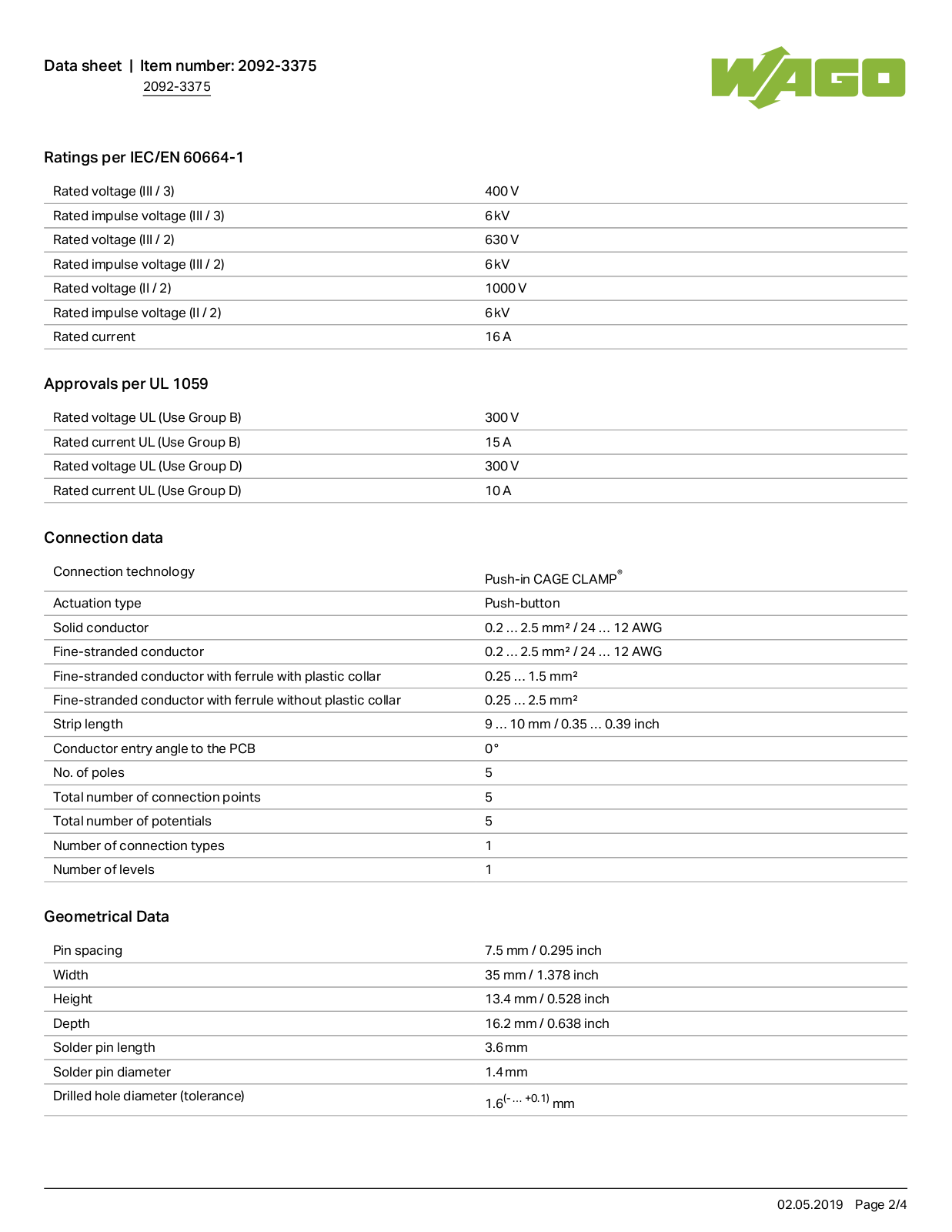
2092-3375
Data Sheet
4 pgs
135 Kb
0
Table of contents
Loading...
Wago 2092-3375 Data Sheet
...
Wago Data Sheet
Download
Specifications and Main Features
Frequently Asked Questions
User Manual
Download
Page 1
Page 2
Page 3
Page 4
Loading...
+
hidden pages
Unhide
You need points to download manuals.
1 point = 1 manual.
You can buy points or you can get point for every manual you upload.
Buy points
Upload your manuals
 Loading...