

Page 1
Page 2

X
E
®
T
he Rapid RH
®
moisture testing system
should be used on any project where
moisture-sensitive floor coverings or coatings
are to be applied over concrete slabs. Owners,
General Contractors, Flooring Contractors/
Installers and Testing Companies need to
be sure the tests they perform are accurate,
repeatable and available to all who need
to know the current moisture condition of
concrete slabs.
R
apid RH
®
significantly improves your
project team’s ability to instantly test and/
or monitor the drying progress of a concrete
slab without adding substantial cost to the
project. The Rapid RH® enables you to take
fast, accurate periodic readings that fully
comply with industry standards. The Rapid
RH® “Smart Sensors” are factory-calibrated
and use CMOS Sens
®
technology, to ensure
the sensor’s accuracy and fast equilibration.
Page 3
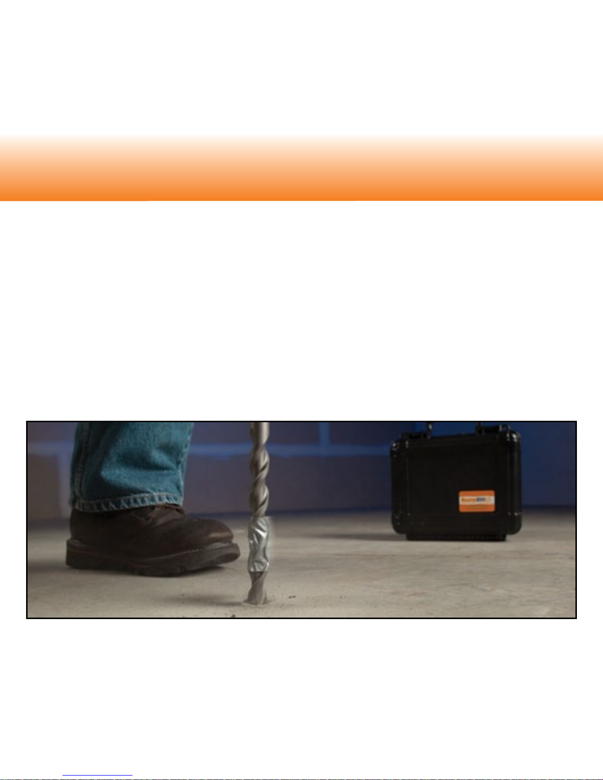
Correct hole-depth is important in complying with the ASTM F2170 standard. Drill
a hole in the concrete slab to the required depth using a rotary-hammer drill and a
¾” (19mm)-diameter masonry drill bit. Per the ASTM F2170 standard, drill the hole
to a depth equaling 40% of the slab’s thickness for slabs that are drying from one
side, or 20% depth for a slab drying from two sides. For proper Rapid RH® 4.0 EX
installation, be sure to position the drill perpendicular (90˚) to the surface being tested.
TIP: If you do not have a depth-gauge for your drill, mark or tape-off your drill bit
to the correct depth setting. Vacuum around, and periodically in the hole as you
drill to better see your progress and use the depth ruler supplied with your Rapid
RH kit to check your depth progress to keep from over-drilling.
Step 1: Drill the Hole
Page 4
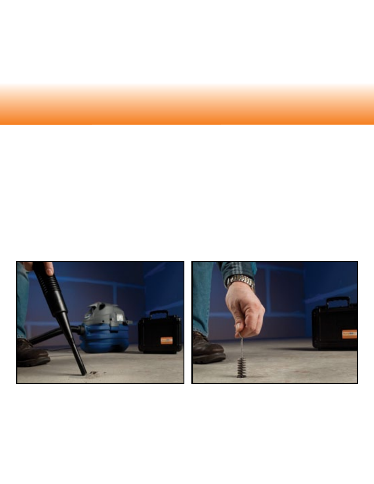
Attach the vacuum attachment to the straight extension of a shop vacuum cleaner
hose* and thoroughly vacuum up the dust in and around the hole.
Next, insert the wire bristle brush into the hole. Turn the brush several times to loosen
pulverized concrete from the walls of the hole. Vacuum again. Repeat this step twice
to ensure no loose concrete particles remain in the hole.
Step 2: Clean the Hole
*The vacuum attachment may require an adapter depending on vacuum model.
Page 5
NOTE: The newest ASTM F2170 standard (F2170-11) has a revision (from the previous -09
version) calling for the ‘sleeve’ (liner) to go from the top to the bottom of the hole. The new
Rapid RH
®
extension insert approach allows you to easily adhere to this new revision of
the ASTM test method. Additionally, the main, smooth sleeve section of the Smart Sensor
barrel is now detachable, allowing for even more convenient use of only the bottom ‘nned’
section of the barrel in shallow-hole applications such as thin topping slabs, etc.
Directly out of the package, the Smart sensor is 1.6” or 40% of a 4” slab. ASTM F217011, Section 10.2 states: “Slab drying from top only (Example: slab on ground with vapor
retarder below, or slab on metal deck): 40% depth. Slab drying from top and bottom
(Example: elevated structural slab not in metal deck): 20% depth)”. Each Smart Sensor
pack includes ten (10) short (0.4”) extensions that can be inserted into the Smart Sensor
barrel to enable use in thicker slabs. Adding one insert extends the Smart Sensor barrel
length to 2” for testing 5”-thick slabs to the 40% depth. Keep any unused extensions for
future jobs. If need be, you can use additional extensions to increase the length of the
sensor barrel for thicker slab applications.
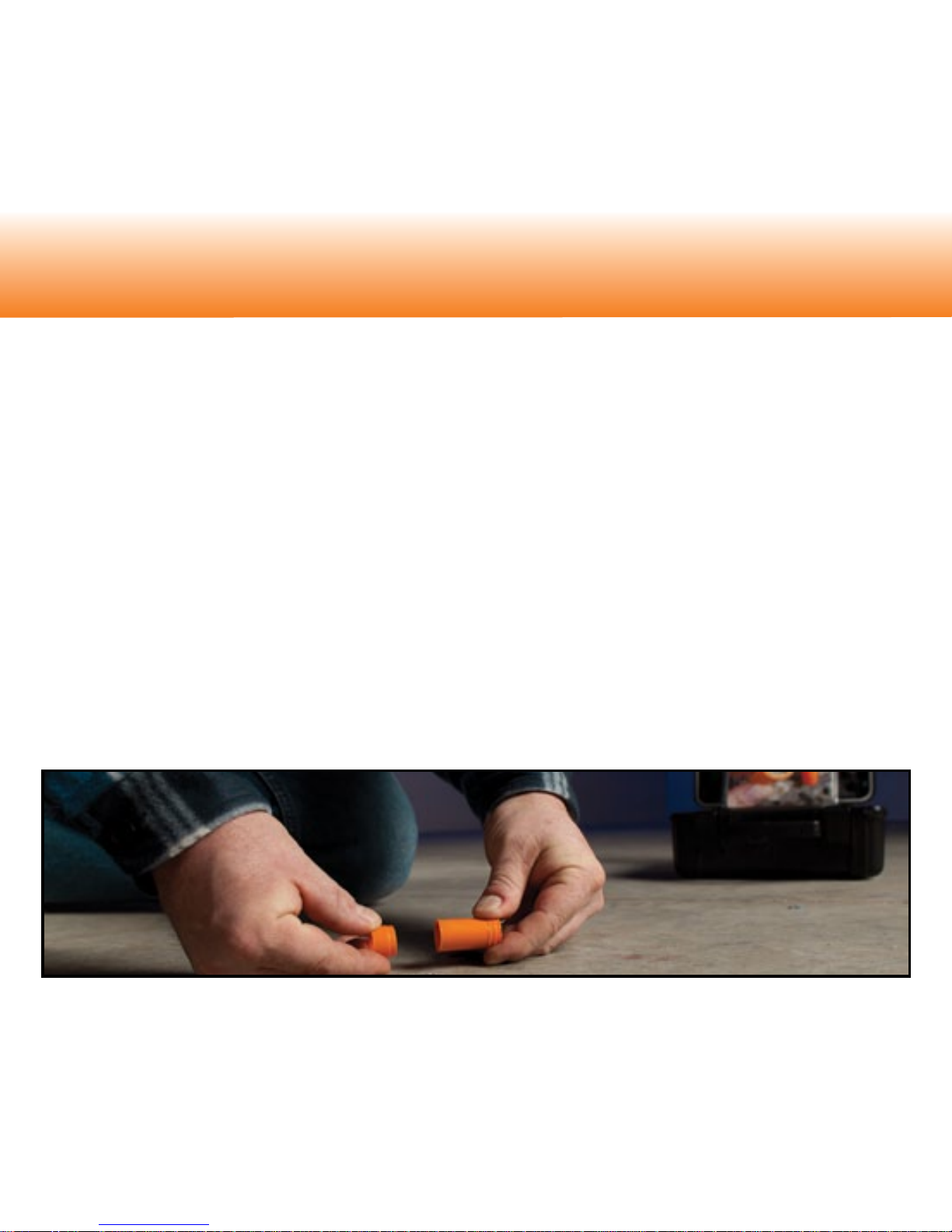
Step 3: Insert the Smart Sensor
Adding an extension
Page 6

In summary, you add one extension insert to a Smart Sensor barrel for every 1” increase
in slab thickness over 4” to meet the 40% depth requirement. The extension inserts
make the Smart Sensor’s usage exible for varying thicknesses of concrete.
Now, take the Smart Sensor directly out of the package. With no extensions installed,
insert the Smart Sensor into the hole with the white insertion tool. Push and/or lightly
tap the top of the insertion tool until you feel that the bottom of the Smart Sensor has
seated on the bottom of the hole. The smooth sleeve section of the Smart Sensor may
slightly separate from the bottom, nned section of the Smart Sensor, leaving part of
the sleeve exposed above the concrete surface. At this point, for 1.6” depth holes (40%
of 4”) insert a protective cap into the top of the sleeve, and push and/or tap down to the
concrete surface. If testing in thicker slabs insert the proper number of extensions rst
before pushing or tapping down with the protective cap.
Remember: Correct depth of hole is critical to correct adherence to the ASTM F2170
test method.
Caution: NEVER use the Easy Reader to install the Smart Sensor.
Insert Smart Sensor Using Orange Cap
Insert Smart Sensor
Using Insertion Tool
Page 7

When ready to take readings, remove the orange protective
cap from the Smart Sensor, and ensure no dust or debris are
inside. Insert the Rapid RH® 4.0 Easy Reader rmly until it
comes fully into contact with the bottom of the Smart Sensor.
Hold the Easy Reader in place until the rst relative humidity
reading appears on the screen (about three seconds),
then immediately remove the Easy Reader. The display
will toggle back and forth between the relative humidity
value (when the cursor is next to the %RH symbol) and the
temperature value (when the cursor is next to the °F or °C
symbol*). Once the Easy Reader is removed from the Smart
Sensor, the readings from that Smart Sensor will continue to
display for approximately 5 minutes or until the Easy Reader
is reinserted into another Smart Sensor. After removal, wait
at least 5 seconds before inserting the Easy Reader into
another Smart Sensor. Replace the Easy Reader’s plastic
end caps when not in use.
In most cases, one hour after installation, the Smart Sensor
will generally give a reading within 3% RH of the reading
you would see after the ASTM-required 72-hour mark. Just
remember to follow the ASTM F2170 procedures pertaining
to equilibration time.
Step 4: Take Readings
Easy Reader
inserted into a
Smart Sensor
Page 8

After the initial equilibration has been reached per ASTM F2170 requirements,
subsequent readings can be taken instantly. If future testing is needed, replace the
protective cap by snapping it back into the Smart Sensor.
Record readings on the enclosed report form in the spaces provided for information
required by ASTM F2170, including the date, time, %RH and temperature. The grid at
the bottom of the report form can be used to record test-hole locations. Each Smart
Sensor is serialized on the outside of the Smart Sensor. Extra copies of the report
form and an ASTM F2170 checklist can be downloaded at www.RapidRH.com. You
can also visit www.rhspec.com to visit links to various nished ooring manufactures’
installation guides and their RH thresholds. For any additional questions related to
what RH levels are appropriate, please contact the manufacturer of the product
to be applied to the concrete slab.
*Rapid RH® 4.0 Easy Readers that display temperature in Celsius can be identied by their blue labels and
blue plastic protective caps.
Record readings on report
form included with
Smart Sensors
Page 9

If future readings are no
longer needed (for example,
when ready to apply a oor
covering or coating), place
the stainless steel metal
disk over the Smart Sensor
and skim-coat the hole with
a cementitious patching
compound compatible with
the ooring manufacturer’s
installation instructions.
Step 5: Encapsulate Smart Sensor
Place metal disk over Smart
Sensor before encapsulating
Apply cementitious
patching compound
Page 10

Display shows “ER”: The Rapid RH® 4.0 Easy Reader may not be properly communicating
with the Smart Sensor for the following reasons: (1) The Easy Reader was not in contact
with the Smart Sensor long enough. Hold the Easy Reader in the Smart Sensor until the
rst relative humidity reading appears on the screen, then remove. (2) Debris is blocking
proper contact. Check the Smart Sensor housing for any debris. Try gently twisting the
Rapid RH® 4.0 Easy Reader back and forth a few times to “sweep” away any particles that
may have blocked complete contact. If this does not work, vacuum out the housing.
Replace the batteries: The Easy Reader comes with two AAAA alkaline batteries. If
batteries are low, the display will read “LO.” Replace batteries immediately. To replace
the batteries, open up the battery cover by removing the one battery cover screw with
a jeweler’s Phillips screwdriver. DO NOT OPEN UP THE FULL BODY OF THE EASY
READER AT ANY TIME.
Trouble Shooting
The Rapid RH® 4.0 EX is intended for interior use only. It is imperative that the interior application
area be protected from weather elements such as rain and snow to prevent water intrusion. The Rapid
RH® 4.0 EX is not to be used in concrete less than 28 days old. Follow ASTM F2170, Standard Test
Method for Determining Relative Humidity in Concrete Floor Slabs using in situ Probes1.
NIST2 traceable accuracy:
Readings at +/- 2% RH from 50% to 90%
Readings at +/- 3% RH from 90% to 95%
Avoid severe cold or hot storage environments (i.e. vehicles)
1
Available from ASTM International, P.O. Box C700, West Conshohocken, PA 19428-2959, www.astm.org
2
National Institute of Standards and Technology
Use Conditions
Page 11

New concrete slabs should be allowed to cure
and dry as long as possible before performing
any type of moisture testing. Even though some
methods state to wait at least 28 days after a
concrete pour before setting up test instruments,
it is often prudent to wait much longer*.
Minimizing the amount of time between initiating
any moisture testing on a slab and obtaining the
nal results per testing standards increases the
chance that the test results will more accurately
indicate the condition of the concrete around the
test location.
On all slabs (new and old), it is recommended
to do test sampling, prior to complete testing,
according to the ASTM F2170 standard’s
requirement, in regards to the number of test
sites. It is good practice to initially only setup a
portion of the test locations ultimately required
and use those few locations as a means to
indicate when the rest of the tests should be
performed. If extended periods of time have
ASTM F2170 Best Practices
Page 12

elapsed between initially setting up test locations and obtaining the nal results per
testing standards, then it is good practice to set a few new tests to conrm and validate
what the older test locations are currently indicating.
Additionally, it is good practice to let the sensors lay on the slab for about 10 minutes or
so prior to installation, until they reach temperature equilibrium with the slab to prevent
any dew point issues that might cause condensation on or around the sensor (NOTE:
Wagner has not heard of any reports where this has actually been an issue, but it is
still a best use practice). For more information on relative humidity in concrete oors
and moisture testing, go to www.cement.org to order the book “Concrete Floors and
Moisture” by Howard Kanare.
*The drying rate of standard Portland cement-based concrete slabs has been studied
extensively. For slabs drying from one side, a very ‘general’ rule-of-thumb as a drying
rate is approximately 30 days of drying time for each inch thickness of the slab for the
relative humidity level to reach somewhere in the 85%-90% range. This is only a very
rough approximate guideline, and drying times can, and often are, much longer if good
drying conditions (closed-in space, environmental controls on, etc) are not present.
Additionally, other factors such as the densifying of a slab surface from heavy powertroweling, additional water added to the concrete at time of pour, rain or construction
water sitting on a slab, etc, can drastically affect the drying time of a concrete slab.
Page 13

Wagner Meters warrants the Rapid RH® 4.0 EX Smart Sensor and Rapid RH® 4.0 Easy Reader products
against defects in material and workmanship for one (1) year from the date of purchase, subject to the following
terms and conditions:
Wagner Meters’ liability under this warranty shall be limited, at Wagner Meters’ option, to the repair or
replacement of products or any part thereof, which is demonstrated to be defective. To exercise this warranty,
customer must send product back with a copy of the proof of purchase date, the reason for return and, if
Wagner determines it is under warranty, Wagner will replace your product. This limited warranty does not apply
if the product has been damaged by accident, negligent handling, misuse, alteration, damage during shipment
or improper service. Wagner Meters shall in no event be liable for any breach of warranty or defect in this
product, which exceeds the amount of purchase price of the product.
Relative humidity is one of many factors necessary for construction decisions. Wagner Meters does not
assume responsibility for any particular construction decision based on the readings of this instrument and
does not guarantee any specic construction results.
The method of use of this instrument and the interpretation of the readings are beyond the control of the
manufacturer. Wagner Meters cannot accept responsibility for any loss, consequential or otherwise, resulting
from the use of the Rapid RH
®
4.0 EX and its accessories.
The Rapid RH
®
4.0 EX Smart Sensor should be used before the specied expiration date included in the
certicate of calibration. If the Easy Reader does not appear to function properly for any reason, contact
Wagner Meters for remedy.
This warranty is in lieu of all other warranties, whether oral or written, express or implied. Any implied
warranties, including implied warranties of merchantability and tness for a particular purpose, are
excluded. If this product is not in good working order as warranted above, the customer’s sole remedy shall
be repair or replacement as provided above.
This warranty is personal to the customer purchasing the product from Wagner Meters or from its authorized
distributors and is not transferable.
The agents and employees of Wagner Meters are not authorized to make modications of this warranty or
additional warranties binding on Wagner Meters. Accordingly, additional statements, whether oral or written,
except written statements from an ofcer of Wagner Meters do not constitute warranties and should not be
relied upon by the customer.
Wagner Meters Limited Warranty
Page 14

The Moisture Measurement Leader
For more information on relative humidity testing
and to order online go to
www.RapidRH.com
500-R0000-004 rev A
Wagner Meters
326 Pine Grove Road
Rogue River, OR 97537
(800) 634-9961
The RAPID RH® 4.0 EX is registered under U.S. Patent 7231815 & 8047056 Additional Patents Pending
©Wagner Electr onic Pr oduct s, Inc. 2012
All rig hts res erved . No par t of this publication may b e repro duced , stored i n a retri eval syste m, or transmitted, in any fo rm or by any m eans,
electronic, mechanical, photocopying, recording, or otherwise, without the prior written permission of the publisher. The information in this
document is subj ect to ch ange wi thout notice.
 Loading...