

T
he R ap id R H™ mo is tu re t es ti ng s ys te m
should be a par t of the over all moi sture testing
pr og ram on any pr oject wh er e moistu re -s en sitive
finishes are to be applied. O wners, General
Co nt ra ctors, Fl oo ring Cont ractors and I nsta ll er s
ne ed to b e sure th e te st s they pe rform are
ac curate , repeata bl e, and available to al l who
wa nt to know the cu rrent mo is tu re c on di ti on o f
a sl ab o n th ei r pr oj ec ts.
T
he Rapid RH™ is a tool th at si gn if ica nt ly
im pr oves th e pr oj ec t team’s a bi li ty to
in st an tl y test an d/or monito r the drying pr ogress
of a concr ete slab wi th ou t ad ding substantial
cost to the project. The Rapid RH™ enables
yo u to ta ke per iodic rea dings wi thout having
to c onduct other types of te st in g. T he f ac to r ycali br at ed “ Sm ar t Sens ors” usi ng CMO S Sens™
te ch no lo gy in sure s the s en so r’s acc ur acy and
fa st e qu il ib ra ti on .
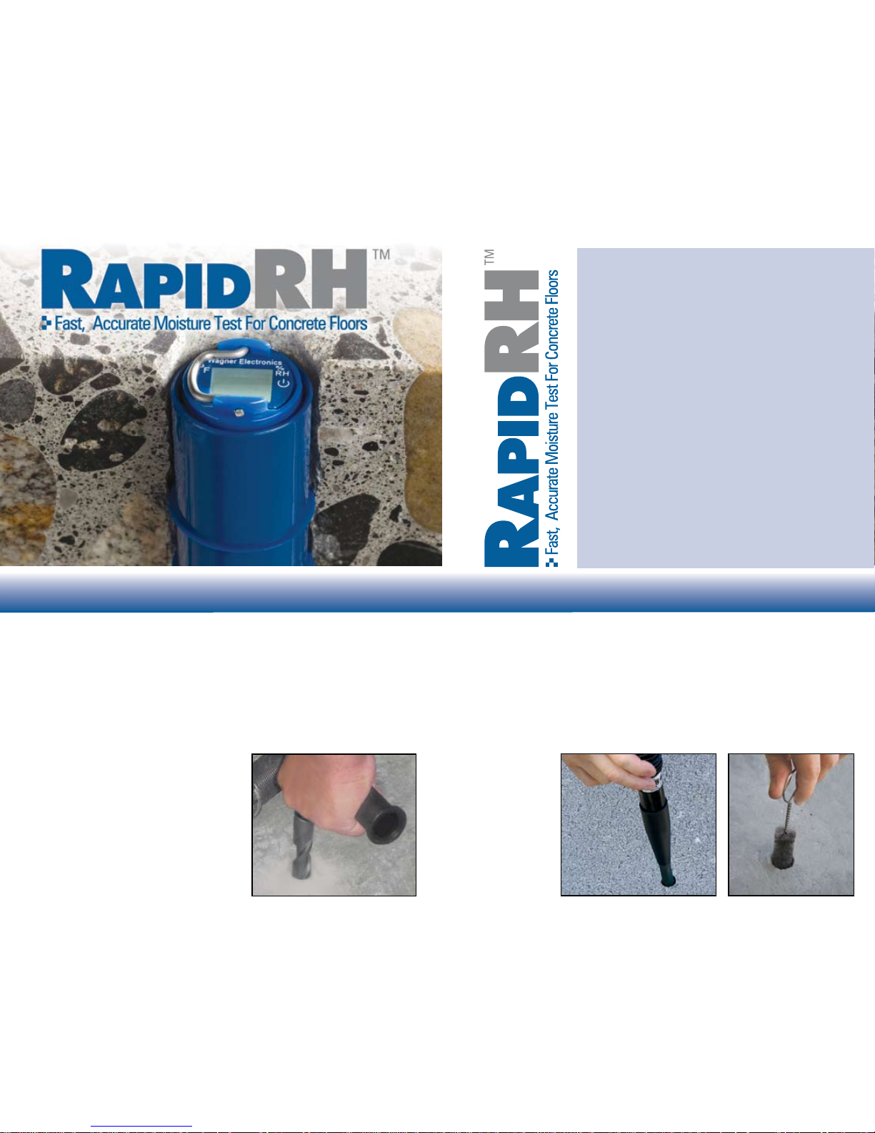
Drill hole to the desired depth in concrete using a rotary-hammer drill and a ¾” SDS
drill bit*. Per ASTM F2170-02 standards, drill the hole to a depth of 1¾” (44 mm),
which is approximately 40% of the depth of a 4” (100 mm) concrete oor slab
poured on grade. For proper RAPID RH™ installation, be sure to position the
drill perpendicular (90˚) to the surface being tested. It is recommended that a drill
capable of approximately 750 rpm be used with the SDS drill bits.
For other slab thicknesses and drying conditions, please consult ASTM F2170-02
to determine the proper depth of the hole.
If the drill bit becomes extremely hot from
drilling several holes in rapid succession, allow
the bit to cool before drilling more holes.
*Champion, Hilti, Milwaukee,
Bosch, DeWalt, Relton
Installation Instructions
Step 1: Drill the Hole
Use a vacuum cleaner, or dustpan and brush to sweep up the dust around the
hole. Attach the Rapid RH™ vacuum attachment to the straight extension of a
Shop-Vac vacuum cleaner hose. Insert the vacuum attachment into the hole and
vacuum the dust within.
Remove the vacuum cleaner extension from the hole and insert the special wire
bristle brush (provided with the kit) into the hole. Turn the brush several times to loosen
pulverized concrete from the walls of the hole. Vacuum again and repeat this step twice.
Step 2: Clean the Hole
*Vacuum hose
diameters vary.
Vacuum Attachment
may require 2 ½” - 1 ¼”
coupler depending on
vacuum model.
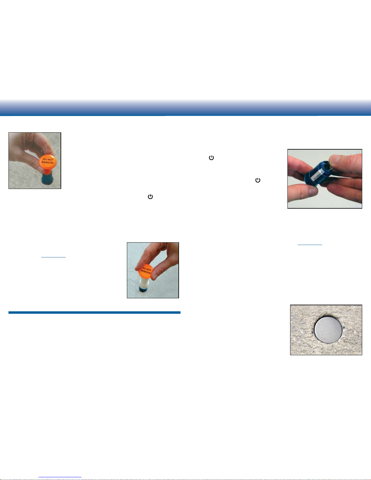
Remove a Smart Sensor probe from its protective
package. Remove white serial number strip from inside
the Smart Sensor (see step 4 below for serial number
strip placement instructions). If this is the rst time you
have used a Rapid RH™ system, please place the Rapid
RH™ Reader into the Smart Sensor. This preliminary
test will make it easier to align the reader once the Smart
Sensor is inserted into the concrete.
To properly insert the Reader, line up the white serial
number strip on the Smart Sensor with the white serial
number strip on the Rapid RH™ Reader. Insert the
Reader, twist 45 degrees clockwise and press the “ON” button. Verify that
numbers appear on the screen (see step 4 for instruction on taking readings)
Next, insert the Smart Sensor into the drilled hole. (Make sure that the Rapid
RH™ Reader is not installed in the Smart Sensor.) Use the orange plastic insert
tube attached to an orange cap and rmly press the Smart Sensor into the hole
until the Smart Sensor seats itself at the bottom of the hole.
For a 1¾” (44.5mm) deep hole, the top of the Smart Sensor will be approximately
¼” below the surface of the concrete.
For holes deeper than 1¾” (44.5mm) use the white insertion
tool (avaible at rapidrh.com).
To keep debris from getting into the Smart Sensor place
the protective cap with the orange insert into the Smart
Sensor until ready to take readings.
Follow ASTM F2170-02 procedures pertaining to
stabilization time. The Smart Sensor has an equilibration
time of 30 minutes to several hours depending on
concrete and conditions.
Step 3: Place the Probe
Installation Instructions
Insertion Tool (for deeper holes)
Remove the orange protective cap. Line up the white serial number strip on the
Rapid RH™ Reader with the white serial number strip on the Smart Sensor. Insert the
Rapid RH™Reader, push down slightly, twist
45 degrees clockwise and press the “ON”
button. If the display shows “- -” or “ER” the
Rapid RH™ Reader has not been inserted
properly or has been twisted too far. Remove
the Rapid RH™ Reader and try inserting
again. Press the “ON” button. The display
will toggle from the %RH reading and °F
temperature reading. The probe will shut off
automatically after approximately 1 minute
(you can remove the Reader at any time).
Record readings on the enclosed report form
that has spaces for information required by ASTM F2170-02 including the date,
time, %RH and temperature.You can use the grid at the bottom of the report form
to record probe locations. Each Smart Sensor is serialized on the outside of the
Smart Sensor. A copy of the serial number is located inside the Smart Sensor and
must be removed and may be used on the enclosed report form. Extra copies of
the report form can be obtained from our website, rapidrh.com.
After the initial equilibration time of 1-2 hours, subsequent readings can be taken
instantly. If future testing is needed, replace the orange tube attached to the orange
protective cap. The Rapid RH™ Reader can be left in the Smart Sensor covered by
an orange cap. However, if the relative humidity is above 95% it is recommended
that you remove the Rapid RH™ Reader between readings.
Step 4: Take Readings
If the probe will be covered (for example,
applied oor covering or coating), place the
stainless steel metal disk over the probe
and skim-coat the hole using a cementitious
patching compound compatible with the ooring
manufacturer’s installation instructions.
Relative humidity is one of many factors necessary for construction decisions. Wagner Electronics®
does not assume responsibility for any particular construction decision based on the readings of this
instrument and does not guarantee any specic construction results.
The method of use of this instrument and the interpretation of the readings are beyond the control
of the manufacturer. Wagner Electronics® cannot accept responsibility for any loss, consequential or
otherwise, resulting from the use of the Rapid RH™ and its accessories.
The Rapid RH™ should be used within two (2) years of purchase. If the probe does not appear to
function properly for any reason, return the probe to Wagner Electronics® for replacement.
The Rapid RH™ is patented under U.S. Patent 7,231,815.
For more information on relative humidity in concrete oors and moisture testing, go to
www.cement.org to order the book “Concrete Floors and Moisture” by Howard Kanare.
Step 5: Encapsulate the Probe
Orange Insert

The Rapid RH™ is intended for interior use only. It is imperative that the interior
application area be protected from weather elements such as rain and snow to
prevent water intrusion. The Rapid RH™ is not to be used in concrete less than
28 days old. Follow ASTM F2170-02, Standard Test Method for Determining
Relative Humidity in Concrete Floor Slabs using in situ Probes1.
NIST2 traceable accuracy:
Readings at +/- 2% from 50% to 90% (at service conditions1)
Readings at +/- 3% up to 97% (at service conditions1)
Avoid severe cold or hot storage environments (i.e. vehicles)
1
Available from ASTM International, P.O. Box C700, West Conshohocken, PA 19428-2959, http://www.astm.org
2
National Institute of Standards and Technology
It is important to avoid condensation on the Rapid RH™ Smart Sensor. If the
sensor is colder than the dew point temperature of the environment being tested,
condensation can occur causing inaccurate readings and potentially damaging
the sensor. To avoid condensation on the sensor allow the probes to stabilize at
room temperature before removing from the package. This action is especially
important if you bring the Rapid RH™ Smart Sensor from a cold environment
(such as an unheated area of a vehicle) into a building.
Avoiding Condensation
Use Conditions
Wagner Electronic Products, Inc. warrants the Rapid RH™ Smart Sensor and Rapid RH™ Reader product against defects in material and workmanship for one (1) year from
the date of purchase, subject to the following terms and conditions:
Wagner’s liability under this warranty shall be limited, at Wagner’s option, to the repair or replacement of this product or any part thereof, which is demonstrated to be
defective. To exercise this warranty, customer must telephone, fax or e-mail Wagner’s Customer Service Department for a RMA (Return Materials Authorization) number and
factory instructions for shipment. This limited warranty does not apply if the product has been damaged by accident, negligent handling, misuse, alteration, damage during
shipment, or improper service. Wagner Electronic Products, Inc. shall in no event be liable for any breach of warranty or defect in this product, which exceeds the amount of
purchase price of the product.
With proper care and handling, the product should stay in calibration; however, because Wagner Electronic Products, Inc. has no control over the manner in which the unit
will be used, it makes no warranty that the Smart Sensors will stay in calibration for any specic period of time.
This warranty is in lieu of all other warranties, whether oral or written, express or implied. Any implied warranties, including implied warranties of merchantability
and tness for a particular purpose, are excluded. If this product is not in good working order as warranted above, the customer’s sole remedy shall be repair or
replacement as provided above.
This warranty is personal to the customer purchasing the product from Wagner Electronic Products, Inc. or from its authorized distributors and is not transferable.
The agents and employees of Wagner Electronic Products, Inc. are not authorized to make modications of this warranty or additional warranties binding on
Wagner Electronic Products, Inc. Accordingly, additional statements, whether oral or written, except written statements from an ofcer of Wagner Electronic Products, Inc. do
not constitute warranties and should not be relied upon by the customer.
Wagner Electronic Products, Inc.
LIMITED WARRANTY
For more information on Relative Humidity Testing
and to order online go to
www.rapidrh.com
500-RRP01-002
326 Pine Grove Road
Rogue River, OR 97537
(800) 207-2164
The RAPID RH™ is registered under U.S. Patent 7,231,815
Patents Pending
Wagner Electronics
®
©Wagner Electr onic Products, Inc . 2005
All r ights res erved. N o part of t his publi cation ma y be reproduced, stored in a retrieval system, or trans mitted, i n any form or by any means,
electronic, m echanical, photo copying, recordi ng, or otherwise, w ithout the prior wr itten permissi on of the publisher.
 Loading...