

Page 1
OPERATING INSTRUCTIONS, Version SW1203/3.00/ HW3.0
W agner& C
o
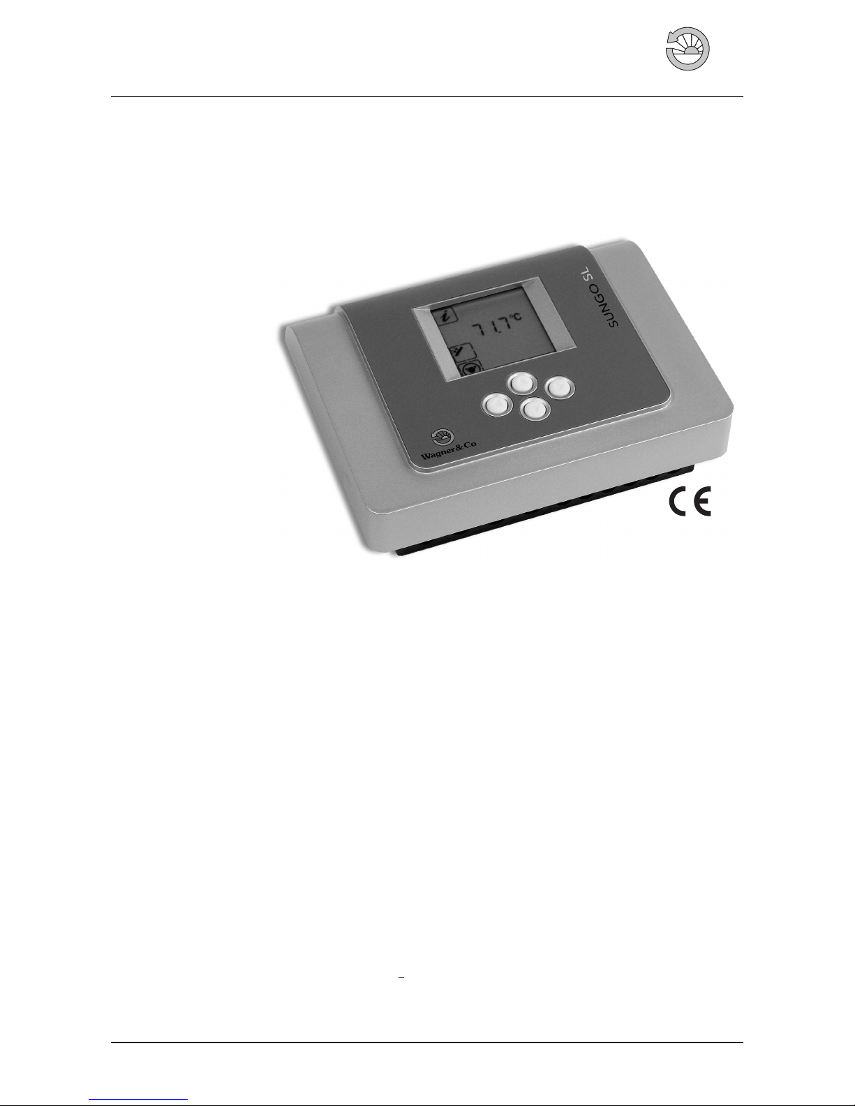
Solar Controller SUNGO SL
W agner& C
o
The benefits at a glance
●
Large illuminated display to indicate temperature, bal
-
ance values and system status with clearly visible sym
-
bols for easy readability.
●
Easy and safe operation via four buttons for vertical and
horizontal scrolling through the menus.
●
Extensive diagnostics for monitoring system functions,
eg. sensor cutoff and monitoring of temperature differ
-
ence “∆T too high”
●
Integrated security functions such as collector cooling,
storage tank cooling, system protection and vacuum
tube collector function.
●
Solar charging of 1 and 2 tank systems
●
Choice of thermostat function or return temperature in
-
crease
●
Balance/reset values
●
5 temperature inputs PT1000
●
1 output, speed-controlled
●
The sensor T5 (solar return) and an external volume
measuring device provide energy measurements
in
kWh.
●
NEW – now also SECUSOL system ready!
Contents
1. Technical Description ................. 2
2. General Safety Guidelines ............... 4
2.1 Installer’sQualifications ................ 4
2.2 OperatingRequirements ............... 4
2.3 Installationand OperatingInformation ....... 4
3. Installation........................ 4
3.1 Installationof the Housing............... 4
3.2 ConnectingWires ................... 5
4. Operation ........................ 6
4.1 Displayand Buttons .................. 6
4.2 InformationMenu ................... 8
4.3 SettingsMenu...................... 9
4.4 ManualOperationMenu ...............10
4.5 SpecialFunctionsMenu ................10
4.6 Service– System Messages ..............11
4.7 Service– Sensor Control ................11
5. Application Examples .................11
5.1 StandardSingleTankSystem .............11
5.2 StandardDualTankSystem ..............12
5.3 SECUSOLSystem....................12
Figure 1 Solar Controller SUNGO SL.
Solar Thermal / Solar Circuit EN-SUNGO-SL_BA-0809-1122P300 · 1316BED008-30B-E 1
Page 2
2 EN-SUNGO-SL_BA-0809-1122P300
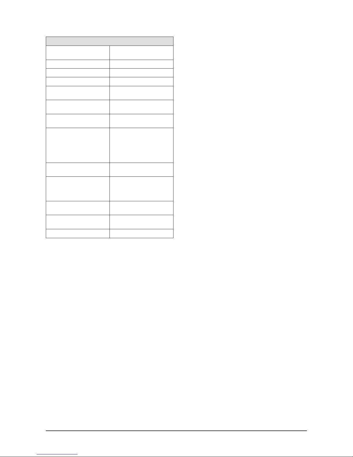
1. Technical Description
Solar Controller SUNGO SL
Material
100 % recyclable ABS-housing
for wall mounting
Dimensions (LxHxWinmm) 173x138x51
Protection type IP40 according to VDE 0470
Rate of radio interference N according to VDE 0875
Operating voltage
230 Volt AC; 50 Hz;
-10% to +15%
Diameter of cable max.
for 230 V connections
2.5 mm² unifilar or finely
stranded
Temperature sensor /
Temperature range
Pt1000; 1000 W at 0 °C;
Range: -30 °C to +225 °C
Sensor load
The cable of the sensor must
be installed with no tension.
The sensor must not be loaded
mechanically when the
temperature of the collector is
more than 60 °C.
Test voltage
4 kV 1 min according to VDE
0631
Switching voltage
Output parameters of switches
230 Volt AC
1A / ca. 230 VA
for cos ϕ = 0.7-1.0 for each
output
Internal mains protection
Microfuse5x20mm;
2 A/T
Operating temperature
(internal) / storage temperature
0° to +50 °C /
-10° to +65 °C
Weight ca. 360 g
Solar Charging
The solar circuit pump is switched on and off by means of a
temperature difference control. The sensors T1 (collector)
und T2 (tank, bottom) are requiredas control elements. The
on/off conditions and the temperature limitation can be
variably set in the settings menu. Note: The temperature
limitation always affects sensor T2 (tank, bottom).
Speed Control
The solar circuit pump can be controlled via speed control
(in this case impulse packet control). This means that indi
vidual sine half-waves in the alternate current are switched
on or off depending on the temperature difference. There
fore the speed can be altered within a range of 30-100%
which results in longer system run times. The minimum
speed can be custom set.
Sensor T3 (tank, top)
Sensor T3 (tank,top) has different functions.By default it is
the measuring sensor for the top of the tank. In that case it
has no switch function and is not monitored by the diag
nostics system.
With the return temperature increase function activated it
functions as ahot sensor (source).Withthe thermostat heat
ing with additional sensor function activated it functions as
an additionalsensor.In both casesthis sensor is used in the
hotareaofthetankandaffectsswitchingoutputA2.
If used in this way the sensor function is monitored as nor
-
mal by the diagnostics system.
Balance Values
In addition to the actual values of the sensors T1 (collector)
and T2 (tank, bottom) the display also shows balance val
ues which represent the smallest and biggest temperature
values for each sensor. After reset the actual temperature
value is displayed.
Manual Operation
Allows switching inputs andoutputs on or off manually. On
exiting themanual operation menu,the software returns to
automatic operation. The manual operation menu can be
used for amaximum of 8 hours. After that the softwareauto
matically switches back to automatic operation and to the
information menu.
Manual Lag Function
In order tocheck the temperature valuesin the information
menu even when the outputs are set manually, a time lag
has to be selected in the manual lag function in the manual
operation menu. On exiting the manual operation menu,
this time span passes once and then is set back to zero. In
this mode a blinking symbol for the manual operation is
shown in the information menu.
Collector Cooling
The tank is loaded up to the preset temperature limitation
which affects sensor T2(tank,bottom).If the preset temperature limitation is exceeded output A1 (solar circuit pump)
switches off. If the temperature of T1 (collector) then rises
above theselectable standardvalue of 110 °C the solar circuit pump is switched on in order to cool the collector. It
switches off again when the temperature at the collector
sensor has decreased by 10 K.
This type of intermittent operation of the solarcircuit pump
means that the collector is never or only rarely in an idle
state. If the preset tank temperature limitation is exceeded
by 5 Kthecollector cooling functionissuppressed.Thesys
tem shuts down completely.
Storage Tank Cooling
Storage TankCoolingmeans that ifnecessary the tanktem
peraturecan be reduced downtoa preset lowest switching
off value (setting for vacations).
When the collector cooling function is activated storage
tank cooling will also become active.
In order for storage tank cooling to become active the fol
lowing 3 conditions must be met:
1. Temperature T2 (tank, bottom) must be higher than or
equal to the preset tank temperature limitation plus 2 K.
2. Temperature T2 (tank, bottom) must be higher than the
preset switching off value for storage tank cooling.
3. Temperature T1 (collector) must be lower than tempera
ture T2 (tank, bottom) minus 10 K.
In order forstorage tank coolingto switch offone of the fol
lowing 2 conditions must be met:
1. Temperature T2 (tank, bottom) is lower than the switch
ing off value for storage tank cooling.
2.Temperature T1(collector) must be higher than tempera
ture T2 (tank, bottom) minus 2 K.
Page 3

EN-SUNGO-SL_BA-0809-1122P300 3
Vacuum Tube Collector Function
The vacuum tubecollector function allows operation of the
solar heating system even if sensor T1 (collector) is in
-
stalled in the connecting pipe of the collector. If the tem
-
perature increase at sensor T1 exceeds the preset switch
ing on value for the collector temperature increase
(standard: 1K) the solar circuitpumpis switched on forthe
duration of a preset lag time (standard: 15 s).
During this time the switching on difference and the solar
charge between sensor T1 (collector) and sensor T 2 (tank,
bottom) has to be activated, otherwise the solar circuit
pump will switch off again.
The rise intemperature at sensorT1 (collector) ismeasured
again immediately after the last runtime of the pump.
System Messages
The system messages for interrupted or shorted-out sen
sors are represented by symbols on the display.For better
recognition of the system messages
the display illumina
tion switches on and off every second as long as the error
prevails and no key entry is made.
Triac
The Triac is anelectronic on/off switchfor the 230Voutputs
of the SUNGO Controller.
Function: A triac switch consists of 2 diodes which can be
switched anti-parallel (= antiparallel thyristors). The
thyristors switch through the positive or negative sine halfwave as long as a switching on difference exists. The triac
switch switches off when the temperature falls below the
switching-off difference.
System Protection
In order to protect the system components (solar circuit
pump, 2 or 3 way valves etc.) in the solar heating circuit
from extremely high temperatures the solar charge is
stopped completely if a temperature limit at the collector
sensor is exceeded, even if this was permitted on account
of a temperature difference between sensor T1 (collector)
and sensor T2 (tank, bottom).
The standard temperature value for activating the system
protection function is 135 °C. However, this value can be
variably set within a range of 115° to 200 °C.
Dual Tank Operation
The SUNGO SL is capableof controlling a dual tank system
by using output A2 for switching between tanks with the
help of a 3 way valve.Change the menuitem 0–1to0–2in
order to control a dual tank system.
Note: If the dual tank option is selected menu item 10 can
no longer be activated.
Preference
The SUNGO SL always uses tank 1 as a preference for the
dual tank option. This cannot be changed.
Thermostat
The thermostat function for switching on can be set at a
range between 0° to 130 °C with a variable difference be
tween 1 to 40 K for switching off.Choose between the op
tions heating and cooling.
With the heating option activated output A2 switches on if
the current temperature T4 fallsbelow the preset switching
on level. Output A2 switches off if the current temperature
T4 is higher than the switch-on level plus the switch-off dif
ference.
With the heating option an additional sensor T3 can be ac
tivated. If this is the case A2 is only switched on if tempera
ture T3 ishigher than theswitching on level plus the switch
ing off difference plus the additional difference for T3.
With the cooling option activated output A2 switches on if
the current temperature T4 falls below the preset switch
level. Output A2 switches off if the current temperature T4
is lower than the switch level minus the switching off
difference.
There are 3 independent time windows available for the
thermostat. If no time window is activated time window 1
has to be set to 0:00 and 23:59.
Return Flow Boost
This is a freely adjustable temperature differencefor simple
heating support which leads the heating return-flow T4
(drain) to the heating boiler, either directly or via the solar
tank, depending on the preset temperature difference to
the tank sensorT3 (source) , by switching the3 way valve on
output A2.
Note: In addition to the switching phase (black) on output
A2, the switching head also requires a constant phase
(brown).
SECUSOL Function
The solar heating systemisoperated on a drainback princi
ple. This means if the solar circuit pump is not activated
there is no solar fluid in the collectors and risers. See
SECUSOL instructions for further details.
Measuring the Yield
For measurements of the solar yield in kWh.The heat yield
is measured with a volume flow metre connected to input
T7, an additional sensor T5 (return) and the existing sensor
T1 (collector).
Page 4
4 EN-SUNGO-SL_BA-0809-1122P300
2. General Safety Guidelines
The following safetyadvice is designedto protect youfrom
dangers that can arise from improper handling of devices,
whether intentional or otherwise. A distinction is made be
tween general advice presented here and specific advice
presented throughout the guidelines.
DANGER for danger to the person
Improper electrical installation of the device can lead to
potentially fatal electric shocks as well as other health
hazards.
CAUTION for danger to property
This symbol indicates dangers that can result in damage to
the components or the function of the control.
NOTE for additional information
This symbol indicates practical advice and tricks of the
trade which will be useful for installing and operating the
control.
2.1 Installer’s Qualifications
●
Setting up and commissioning of the SUNGO SL must
be carried out by a qualified installer.
●
All national andlocal safety regulationsneed to be com
-
plied with.
●
Please note that in case of a complaint the guarantee is
only valid if correct commissioning has been certified in
a commissioning report.
2.2 Operating Requirements
Application
●
Controlling solar thermal systems through the selection
of applicable control patterns and additional functions
to adaptthe control forthe required operation of the hy
-
draulic system.
●
The control must only be operated in dry rooms.
●
The control can be integrated into the solar circulation
unit or mounted on the wall.
Limitations of use
●
If usedina non-solar thermalapplicationthe functionality
of thecontrol hastobe checked before commissioning.If
in doubt contact the control service of Wagner & Co.
●
If these operating requirements are not observed any
claims under the warranty will not be accepted.
2.3 Installation and
Operating Information
●
Any installation and wiring work has to be carried out in
an idle state as during operation the voltage on the out
-
side of the triacs is 230 V.
●
Mains power mustbe connected to thecontrolfrom out
side the solar station via an external ON/OFF Switch.
This is also required to activate the special functions
menu through switching the mains power ON/OFF.
●
Operating temperatures above 50 °C are not permitted
for the control.
●
LCD display panels are designed in such a way that a
specific reading position isrequired.When installing the
control, be careful to place the display so that it is at eye
level or slightly higher. This way you can ensure optimal
display contrast.
●
The base of the control is divided into a safety low volt
age section and a 230 V section by a crosspiece. Make
sure that you do not confuse these sections during the
installation process.
● The default operating mode is the automatic mode.
Manual operation is used only for functional testing of
the different hydraulic components (pump, 2/3 way
valve). In this operating mode maximum temperatures
or sensor functions are not monitored.
● Do notoperatethesystemif the control,the wiring or the
connected 230 V mains are visibly damaged.
● The control is fitted with a mains microfuse.
● Collectors and hydraulic pipework can get extremely
hot during sunny periods. There is a risk of scalding
when fitting the collector temperature sensor.
3. Installation
3.1 Installation of the case
Opening the case
●
No tools are required to open the control case. The lid
folds overon top of the lower half. Youcan dislodge and
lift up the lid by pulling gently on the side clips.
●
When fully opened the lid will not move so that you can
take care of mounting and wiring comfortably.
Wall mounting
●
Use the supplied drillingtemplatetodrill the fixing holes
for the controller.
●
Mount the control to the wall.
●
Do not overtighten the screws to avoid damage to the
lower part of the housing.
Page 5

EN-SUNGO-SL_BA-0809-1122P300 5
Installation in the Solar Circulation Unit
●
With the screws mount the SUNGOSL on the wall holder
of the solar circulation unit.
●
Break out the cable feeds which are located on the base
housing next to the crosspiece.
●
Strip the 230 V cables in a way that the insulated single
cables start directly at the feed to the base housing.
●
Hold cable clamps steady when screwing tight in order
to minimisepressure on the circuit board. Thereis a dan
-
ger of the terminals to be torn off!
●
Finally connect to mains power.
●
When the controlis switched onthe voltage on thetriacs
housing is 230 V AC.
3.2 Connecting Wires
Layout of the SUNGO SL Connections
All electrical connections are made to the circuit board at
the bottom of the control. The sensor connections (safety
low voltage)are located onthe right hand side andthe 230
V mains connections and the switching outputs A1 and A2
on the left hand side.
General connection rules
●
If flexiblewires are used andthe control iswall mounted,
a strain relief must be fixed within or outside of the con
-
trol.
● In this case you must crimp the wire ends.
● If requiredPG9 screws canbe fixed atthe feed-throughs
in case of wall mounting.
230 V mains connection
●
Mains power is connected from outside the control via
an ON/OFF Switch.
This switch is not required if mains power is with a pro
tective plug to a socket.
●
The control is suitable for mains operation at approx.
230 V/50 Hz.
●
All earth wires are connected to the PE terminals.
●
The neutral terminals (N) are connected electrically.
●
Switching output A1 is a 230 V normally open contact
which is activated via speed-control. Switching output
A2 is purely a normally open contact.
Connecting the temperature sensors
●
The wires of the temperature sensors can be extended:
Up to 15 m length, 2 x 0.5 mm² cable can be used, be
yond 15 m and up to 50 m 2 x 0.75 mm² is necessary.
Shielded cables should be used for long connections to
the collector.
Do not connect the shielding at the sensor end,just trim
and isolate.
●
The polarity of the temperature sensors is irrelevant and
they can be connected either way.
●
The sensor wires mustbeinstalled separately from 230V
mains cables.
Lightning Protector Module
The SUNGO SL is fitted with spike protection on all sensor
terminals. Generally, further protection of the tank sensors
is not required.
Sensor T1 (collector) should be fitted with the sensor
con-
nection box SP2 with an overvoltage protection.
FUSE 5X20
T1 T2 T3 T4 T5
M
MMM
PE-PE A2
A1 L1
PE-PE N N N
M
ControllerIC
Triac
Plug for Display
Trafo
Potential Earth
Switching output
Solar circuit pump
Mains L1
Collector sensor, T1
Tank sensor, bottom,T2
Tank sensor, top /
Additional thermostat sensor /
return flow boost (source)
Thermostat /
return flow boost (sink), T4
Heat meter (yield), return flow sensor, T5
T7
M
“Volume flow meter” for yield measurement, T7
Figure 2 SUNGO SL circuit board components.
Page 6

6 EN-SUNGO-SL_BA-0809-1122P300
4. Operation
4.1 Display and Buttons
!
dT min max start stop
R
R
ok?
88888
°C %
KWh
x
Manual operation menu
Special functions menu
Balance or
start / stop values
Units
Tank temp., top/
thermostat additional senso
r
Temperature thermostat/
return flow boost (sink)
Time slot thermostat
Tank temp., mid section/
return flow boost (source)
Confirm and
save symbol
System error
Settings menu
Information menu
Temperature difference
Numerical display for temp.
or sensor errors
Collector temperature
Symbol for reset value
Tank temp., bottom
Pump ON/
Pump OFF
Output A1
Output A2
Page 7

EN-SUNGO-SL_BA-0809-1122P300 7
dT max
__K
dT min
__K
__°C
T max
dT
__K
dT
__K
__°C
T start
__
d max
d min
__
__K
dT
4
4
1
__:__
__°C
T max
__°C
__K
__K
T min
dT max
dT min
I
I
2
2
2
3
3
__:__
__:__
__:__
__:__
__:__
__:__
R
R
R
R
stop
start
stop
start
stop
start
2
2
2
__°C
T min
Horizontal operating level
Vertical
operating level
Set values
Settings menu
as an example
Ý
Decrease
value
Ý
Increase
value
Activate
save function
ÝÝ
Activate
value
Save
value
Switching off diff. T3 - T4,
return temperature increase
Switching on diff. T3 - T4,
return temperature increase
Min temp. level,
return temperature increase
Temp. limitation,
return temperature increase
Stop time window 3, thermostat
Start time window 3, thermostat
Stop time window 2, thermostat
Start time window 2, xx thermostat
Stop time window 1, thermostat
Start time window 1, thermostat
Temperature limitation tank, bottom
Switching on difference T1 - T2, solar
Switching off difference T1 - T2, solar
Min. temp. source
Design temp. diff. speed control, solar
Min. speed, solar circuit pump
Max. speed solar circuit pump (SECUSOL)
Charge time solar heating system (SECUSOL)
Current time
Switching on temperature, thermostat
Switching off temperature, thermostat
Difference additional sensor T3, thermostat
Page 8

8 EN-SUNGO-SL_BA-0809-1122P300
4.2 Information Menu
Information menu
Menu item Description Display
Collector temperature; Current value °C
Collector temperature; Balance; minimum, resettable °C
Collector temperature; Balance; maximum, resettable °C
Tank temperature, bottom; Current value °C
Tank temperature, bottom; Balance; minimum, resettable °C
Tank temperature, bottom; Balance; maximum, resettable °C
Tank temperature, top; Current value °C
Operating hours, total; Balance h
R operating hours since last reset; Balance, display, resettable h
Tank temperature 1 or 2, bottom;
(if 2 tank system is selected) Current value
°C
Tank temperature 1 or 2, bottom;
(if 2 tank system is selected) Balance; minimum, resettable
°C
Tank temperature 1 or 2, bottom;
(if 2 tank system is selected) Balance; maximum, resettable
°C
Operating hours tank 1 or 2, total;
(if 2 tank system is selected) Balance
h
R operating hours tank 1 or 2
since last reset; (if 2 tank system is selected) Balance; display, resettable
h
Thermostat or return temperature increase (drain); Current value °C
Heat counter, return;
(flow value corresponds to collector temperature) Current value
°C
Heat counter, total yield; Balance kWh
R heat counter since last reset; Balance, display, resettable kWh
Heat counter tank 1 or 2, total; Balance kWh
R heat counter, tank 1 or 2
since last reset; Balance, display, resettable
kWh
Pump symbol idle: Operating symbol
Temperature difference (collector, tank) is smaller than required
to activate the solar circuit pump. The solar circuit pump is off.
—
Rotating pump symbol: Operating symbol
Temperature difference (collector, tank) is sufficient to activate
the solar circuit pump. The solar circuit pump is running.
—
min
__°C
__°C
__°C
__°C
__°C
__°C
__°C
__°C
__°C
__°C
__h
__kWh
__kWh
__kWh
__kWh
__h
__h
min
min
max
max
max
__h
R
1
2
__°C
1
2
1
2
1
2
1
2
1
2
1
2
R
R
R
R
__°C
Page 9

EN-SUNGO-SL_BA-0809-1122P300 9
4.3 Settings Menu
Settings menu
Menu item Description Range Default setting
Temperature limitation tank, bottom 15 – 90 °C 85 °C
Switching on difference between collector and tank 3 – 40 K 5 K
Switching off difference between collector and tank 2 – 35 K 3 K
Min. temp. above which the switching difference is analyzed 5 – 90 °C 10 °C
Temperature limitation tank 1 or 2, bottom 15 – 90 °C 85 °C
Switching on difference between collector and tank 1 or 2 3 – 40 K 10 K
Switching off difference between collector and tank 1 or 2 2 – 35 K 3 K
Design temperature difference the speed control adjusts to 2 – 50 K 10 K
Minimum speed of the solar circuit pump
10% increments
30–100% 30%
Maximum speed of the solar circuit pump
Only with SECUSOL!
30–100% 100%
Charge time (s) of the solar heating system with speed 100 %; in 10 s increments
Only with SECUSOL!
20 – 360 s 60 s
Set current time (keep button pressed for faster run-through) 0:00-23:59 0:00
Switching on temperature thermostat
1
0° – 130 °C 30 °C
Switching off difference thermostat
1
1–40K 5K
Additional sensor difference for tank, top, can be selected in heating function.
1
3–20K 10K
Start time slot 1, thermostat
1
0:00-23:59 0:00
Stop time slot 1, thermostat
1
0:00-23:59 23:59
Start time slot 2, thermostat
1
0:00-23:59 0:00
Stop time slot 2, thermostat
1
0:00-23:59 0:00
Start time slot 3, thermostat
1
0:00-23:59 0:00
Stop time slot 3, thermostat
1
0:00-23:59 0:00
Temperature limitation return temperature increase
2
15°–90°C 85°C
Minimum temperature from which the switching on difference is read
2
15°–90°C 20°C
Switching on difference return temperature increase between temperature
measure location T3 and T4
2
3–40K 4K
Switching off difference return temperature increase between temperature
measure location T3 and T4
2
2–35K 2K
1
Only available if heating or cooling thermostat is used.
2
Only available if return temperature increase is used.
dT max
dT min
T max
__K
__K
__°C
dT max
dT min
dT
__:__
__:__
__:__
__:__
__:__
__:__
__:__
T max
d max
T start
T max
dT
dT max
T min
__°C
dT min
d min
1
1
2
1
2
1
2
__K
__K
__K
__K
start
stop
stop
stop
start
start
__K
__K
__K
__°C
__
__°C
__°C
__
__
dT
I
I
2
2
3
3
__°C
T min
2
R
2
R
2
R
2
R
Page 10

10 EN-SUNGO-SL_BA-0809-1122P300
4.4 Manual Operation Menu
Manual operation menu
Menu item Description Range Default setting
Off = 0/On = 1
Switching the solar circuit pump on or off manually (A1)
0–1 0
Off = 0/On = 1
Switching output A2 on or off manually (RLA or thermostat)
0–1 0
Activation of manual operation lag time in automatic mode 0 – 600 min 0 min
4.5 Special Functions Menu
During the first minute after switching on the control
activate the special functionsmenu byselecting it so thatparameterscanbe altered.Themenustays active for 1minuteaf
-
ter exiting it.
On exiting themenuthe parameters can onlybeviewed but notchangedagain.Place the control intheidle position once
again if you need to alter any functions.
Special functions menu
Menu
item
Application Description Range Default
setting
0 System choice
0 – 1: Standard single tank system
0 – 2: Standard dual tank system
0 – 3: SECUSOL system (see SECUSOL instructions for further info)
1–3 1
1
System
Protection
Off = 0/On = 1
Activation of system protection.
Cannot be activated with SECUSOL!
0or1 1
2 System protection start temperature 115 – 200 °C 135 °C
3
Collector
Cooling
Off = 0/On = 1
Activation of collector cooling.
Cannot be activated with SECUSOL!
0or1 1
4 Collector cooling start temperature 100 – 150 °C 110 °C
5
Storage tank
Cooling
Off = 0/On = 1
Activation of tank cooling. Only possible with collector cooling.
Cannot be activated with SECUSOL!
0or1 0
6 Switching off temperature 30 – 90 °C 60 °C
7
Measuring the
Yield
Off = 0/On = 1
Activation of yield measurement
0or1 0
8
Frost protection type
8-1: DC20 for standard systems
8-2: DC40 for vacuum tube collectors (ready mix)
1or2 1
9
Glycol fraction in %.
0% = No Glycol (pure water)
100 % = Pure Glycol (no water)
Note: Glycol fraction for solar circuit can only be selected with DC20!
0–100% 40%
10
Function
selection
10 – 0: Additional functions off
10 – 1: Thermostat, heating
10 – 2: Thermostat, heating with additional sensor T3 (tank, top)
10 – 3: Thermostat, cooling
10 – 4: return temperature increase
0–4 0
11
Vacuum Tube
collector function
Off = 0/On = 1
Activation of vacuum tube collector function
0or1 0
12 Run time of solar circuit pump from reaching the switching on value 1 – 60 s 15 s
13 Switching on value for temperature increase at sensor T1 (collector) 1.0 – 5.0 K 1.0 K
The special functions menus should only be edited by expert personnel. Incorrect settings may adversely affect the solar heating system.
T stop
__
Page 11

EN-SUNGO-SL_BA-0809-1122P300 11
4.6 Service – System Messages
System information with display
Display Description Remedy
System messages
All system messages are displayed with a blinking caution symbol. In case of sensor errors the sensor in
question is also marked with short circuit or interruption symbol.
Interruption
The sensor on the display or the pipe is
interrupted.
●
Test the resistance value of the sensors and compare with
the tables.
●
Check all connections to the sensor.
Short circuit
There is a short circuit on the sensor on the
display, the cable or the output on the
control.
dT too high
A value of 20 K is added to the switch-on
difference between T1 and T2. The message
is displayed if after 30 minutes the total
difference has not been reduced.
●
Check wiring to the pump
●
Check system for air and vent if required
●
Check sensors and sensor wiring, replace sensors if
required
4.7 Service – Sensor Control
Resistance values for Pt1000 sensors in relation to the temperature
-10°C 0°C 10°C 20°C 30°C 40°C 50°C 60°C 70°C 80°C 90°C 100°C 110°C
961 Ω 1000 Ω 1039 Ω 1078 Ω 1117 Ω 1155 Ω 1194 Ω 1232 Ω 1271 Ω 1309 Ω 1347 Ω 1385 Ω 1423 Ω
The working condition of the sensor can be checked with this table and an Ohm meter.
5. Application examples
5.1 Standard Single Tank System
!
Blinking
!
Blinking
!
Blinking
°C
!
Blinking
°C
Ttw
T4
T1
T3
T2
A
AB
B
Vr
P2
P3
TERMO
P1P1
CIRCO
T4A1T1
A2
T2T3
T7
T5
T1
Measuring the yield
Solar
return-flow
Collector field
Cold water
Hot water
Version 1 – TERMO Combi Cylinder
Heating circuit
Oil or gas
boiler
P1: Solar circuit pump
P2: Heating circuit pump
P3: Tank chargingpump
Vr: Switch-over valvefor return temperature increase
T1: Collectorsensor
T2: Tank sensor, bottom
T3: Tank sensor, middle
T4: Sensorheating return-flow
T5: Yield measurement,return flow sensor
T7: Yield measurement,volume flow metre
Collector field
Figure 3 Standard single tank system controlled by SUNGO SL.
Page 12

Figure 4 Standard dual tank system controlled by SUNGO SL.
5.2 Standard Dual Tank System
P3
P2
BWM
T1
T2
T3
Ttw
P1
A1
T1
SECUSOL
Ta
T7
T5
T1
T3
T2
Heating circuit
Hot water
Cold water
Measuring the yield
Solar
return-flow
Collector field (EURO C22)
Oil or gas
boiler
T1: Collectorsensor
T2: Tank sensor, bottom
T3: Tank 1 sensor,top (optional)
T5: Yieldmeasurement, return flow sensor
T7: Yieldmeasurement, volume flow metre
P1: Solar circuit pump
P2: Heating circuit pump
P3: Tank charging pump
Ttw: Hot water sensor (heatingcontrol)
BWM: Thermostatic mixing valve
Collectorfield
5.3 SECUSOL System
P1
P3
P2
P1
CIRCO
Vu
T3 T2 T1T4
A1
A2
M
ECOplus
T1
T5
T7
AB
A
B
T4
T2
T1
T3
Ttw
Collector field
Heating circuit
Oil or gas
boiler
Hot water
Cold water
Solar
return-flow
Collector field
Measuring the yield
P1: Solar circuit pump
P2: Heating circuit pump
P3: Tank chargingpump
Vu: Switch-over valve, tank charging
T1: Collector sensor
T2: Tank1 sensor, bottom
T3: Tank1 sensor, top
T4: Tank2 sensor, bottom
T5: Yield measurement,return flow sensor
T7: Yield measurement,volume flow metre
Figure 5 SECUSOL system controlled by SUNGO SL.
Subject to modifications, errors excepted. · ©Wagner & Co, 2008 · www.wagner-solar.com
12 WAGNER & CO · Zimmermannstraße 12 · D-35091 Cölbe/Marburg ·
☎
+49 6421 80 07-0 · Fax 8007-22
 Loading...