

Page 1
OPERATING INSTRUCTIONS, Issue SW1201/ 2.01/ HW2.4
W agner& C
o
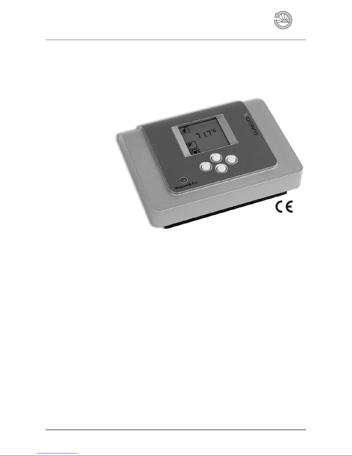
Solar Controller SUNGO S
W agner& C
o
The benefits at a glance
●
Large illuminated display to indicate temperature, bal
-
ance values and system status with clearly visible sym
-
bols for easy readability.
●
Easy and safe operation via four buttons for vertical and
horizontal scrolling through the menus.
●
Extensive diagnostics for monitoring system functions,
eg. sensor cutoff and monitoring of temperature differ
-
ence “∆T too high”
●
Integrated security functions such as collector cooling,
tank cooling, system protection and vacuum tube col
-
lector function.
●
Solar charging of 1 tank systems
●
Current/reset values
●
3 temperature inputs Pt1000
●
1 output, speed-controlled
Contents
1. Technical Description ..................2
2. General Safety Guidelines ...............4
2.1 Installer’s Qualifications .................4
2.2 Operating Requirements ................4
2.3 Installation andOperating Information ........4
3. Installation ........................4
3.1 Installation oftheCase..................4
3.2 Connecting Wires ....................5
4. Operation .........................6
4.1 Display andButtons ...................6
4.2 Information Menu ................... 8
4.3 Settings Menu...................... 8
4.4 Manual Operation Menu................ 9
4.5 Special Functions Menu ................ 9
4.6 Service –SystemMessages ..............10
4.7 Service –SensorControl ................10
5. Application Examples .................11
5.1 Standard Single-Tank System .............11
5.2 SECUSOL System ....................12
Figure 1 Solar Controller SUNGO S.
Solar Thermal / Solar Circuit EN-SUNGO-S-BA-0804-1122P200 1
Page 2
2 EN-SUNGO-S-BA-0804-1122P200
1. Technical Description
Solar Controller SUNGO S
Material
100 % recyclable ABS casing
for wall mounting
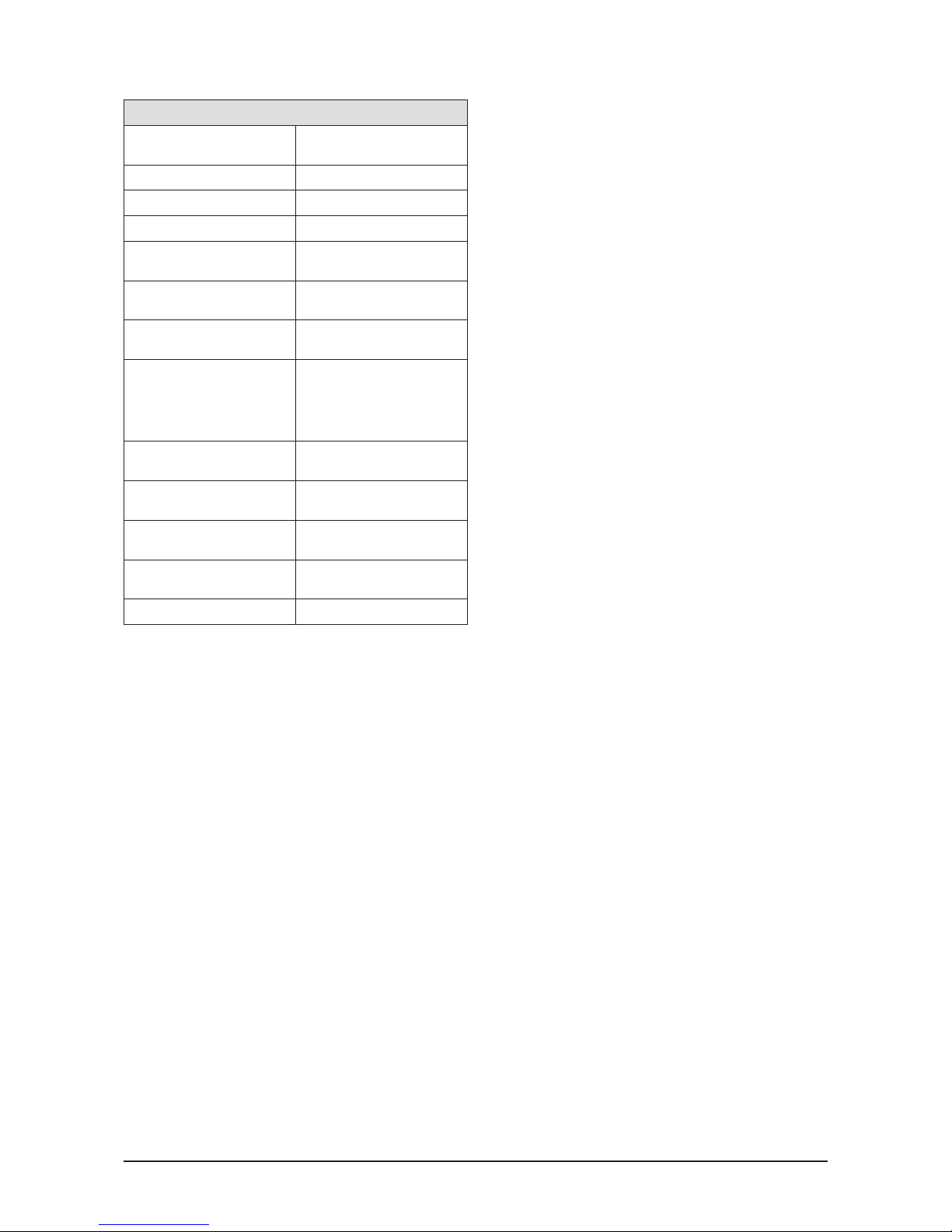
Dimensions (LxHxWinmm) 173x138x51
Protection type IP40 according to VDE 0470
Rate of radio interference N according to VDE 0875
Mains supply
230 Volt AC; 50 Hz;
-10% to +15%
Max. size of wiring
for 230 V-connections
2,5 mm² stranded / single
Temperature sensor /
Temperature range
Pt1000; 1000 Ω at 0 °C;
Range: -30 °C to +225 °C
Strain on sensor
Ensure that the cable does not
put strain on the sensor; Do not
put any mechanical strain on
the sensor if temperature is
above 60 °C.
Test voltage
4 kV for 1 min according to
VDE 0631
Switching voltage
Output parameters of switches
230 Volt AC
1A / 230 VA for cos ϕ = 0,7-1,0
Fuse, internal
Low current fuse5x20mm;2
A/T (2 Ampere, slow)
Operating temperature
(inside), storage temp.
0° to +50 °C / -10° to +65 °C
Weight ca. 360 g
Solar Charging
The solar circulation pump isswitched on and off bymeans
of atemperaturedifferencecontrol.Thesensors T1 (collector) und T2(tank,bottom) are required as control elements.
The on/off conditions and the temperature limitation can
be variably setinthe settings menu. Note: Thetemperature
limitation always affects sensor T2 (tank, lower half).
Speed Control
The solar circulation pump can be controlled via speed
control (in this case impulse packet control). This means
that individual sine half-waves in the alternate current are
switched on or off depending on the temperature differ
ence. Therefore the speed can be altered within a range of
30-100% which results inlongersystem run times.The min
imum speed can be custom set.
Sensor T3 (tank, upper half)
SensorT3 (tank,upper half) is a measuring sensor which in
dicates the temperature in the upper tank area. It has no
switch function and is not monitored by the diagnostics
system.
Balance Values
In addition to the actual values of the sensors T1 (collector)
and T2 (tank,lower half) thedisplay also showsbalance val
ues which represent the min.and max.temperature values
for eachsensor.When reset the current actual temperature
value is displayed.
Manual Operation
Manual operation allows to manually switch input and out
put channels on or off. On exiting the manual operation
menu, the software returns to automatic operation. The
manual operation menu can be used for a maximum of
8 hours.After that the software automatically switches back
to automatic operation in the information menu.
Manual Lag Function
In order to checkthe temperature valuesin the information
menu, even when the output channels are set manually, a
time lag hasto be selected inthe manual lag functionof the
manual operation menu. After exiting the manual opera
tion menu this time span passes once and then is set back
to zero. In this modea blinking symbol forthe manual oper
ation is shown in the information menu.
Collector Cooling
The tank is loaded up to the preset temperature limitation
which affects sensor T2(tank,bottom).If the preset temper
ature limitation is exceeded output A1 (solar circulation
pump) switches off. Ifthe temperature of T1(collector) then
rises above the selectable standard value of 110 °C the so
lar circulation pump is switched on in order to cool the col
lector.Itswitches off againwhen the temperatureat the col
lector sensor has decreased by 10 K.
This type of intermittent operation of the solar circulation
pump means, that the collector is never or only rarely in
an idle state. If the preset tank temperature limitation is
exceeded by 5 K, the collector cooling function is suppressed. The system shuts down completely.
Tank Cooling
Tank cooling means that if necessary the tank temperature
can be reduced to apreset lowest switch-off value (e.g.setting for vacations).
When the collector cooling function is activated tank cooling will also become active.
In order for tank cooling to become active the following 3
conditions must be met:
1. Temperature T2 (tank, lower half) must be higher than or
equal to the preset tank temperature limitation plus 2 K.
2. Temperature T2 (tank, lower half) must be higher than
the preset switch-off value for tank cooling.
3. Temperature T1 (collector) must be lower than tempera
ture T2 (tank, lower half) minus 10 K.
In order for tankcooling to switch off one of the following 2
conditions must be met:
1. Temperature T2 (tank, lower half) is lower than the
switch-off value for tank cooling.
2.Temperature T1 (collector) mustbehigher than tempera
ture T2 (tank, lower half) minus 2 K.
Vacuum Tube Collector Function
The vacuum tubecollector function allows operation of the
solar heating system even if sensor T1 (collector) is in
stalled in the connecting pipe of the collector. If the tem
perature increase at sensor T1 exceeds the preset switchon value for the collector temperature increase (standard:
1 K) the solar circuit pump is switchedon for thedurationof
a preset lag time (standard: 15 s).
During this time the switch-on difference and the solar
charge between sensor T1 (collector) and sensor T 2 (tank,
Page 3

EN-SUNGO-S-BA-0804-1122P200 3
lower half) has to be activated, otherwise the solar circula
tion pump will switch off again.
The rise intemperature at sensor T1(collector) is measured
again immediately after the last runtime of the pump.
System Messages
The system messages for interrupted or shorted-out sen
sors are represented by symbols on the display. For better
readability of the system message the display illumination
switches on and off every second as long as the error pre
vails and no key entry is made.
Triac
The Triac is an electronicon/off switch forthe 230 V outputs
of the SUNGO controllers.
Function: A triac switch consists of 2 diodes which can be
switched anti-parallel (= antiparallel thyristors). The
thyristors switch through the positive or negative sine halfwave as long as a switch-on difference exists. The triac
switch switches off when the temperature falls below the
switch-off difference.
System Protection
In order toprotectsystem components likesolar circulation
pump, 2-/3 way valves etc. that are installed in the solar cir
cuit againstexcess temperatures,solar charging isstopped
entirely as soon as a set temperature limit is exceeded at
sensor T1 (collector), even when charging would still be
possible due to the temperature difference between sen
sor T1 (collector) and sensor T2 (storage cylinder).
The standard temperature value to activate the system pro
tection is set at 135 °C. However,it is possible to set a vari
able value between 115 °C and 200 °C.
Page 4
4 EN-SUNGO-S-BA-0804-1122P200
2. General Safety Guidelines
The following safetyadvice is designedto protect youfrom
dangers that can arise from improper handling of devices,
whether intentional or otherwise. A distinction is made be
tween general advice presented here and specific advice
presented throughout the guidelines. Watch out for the
symbols!
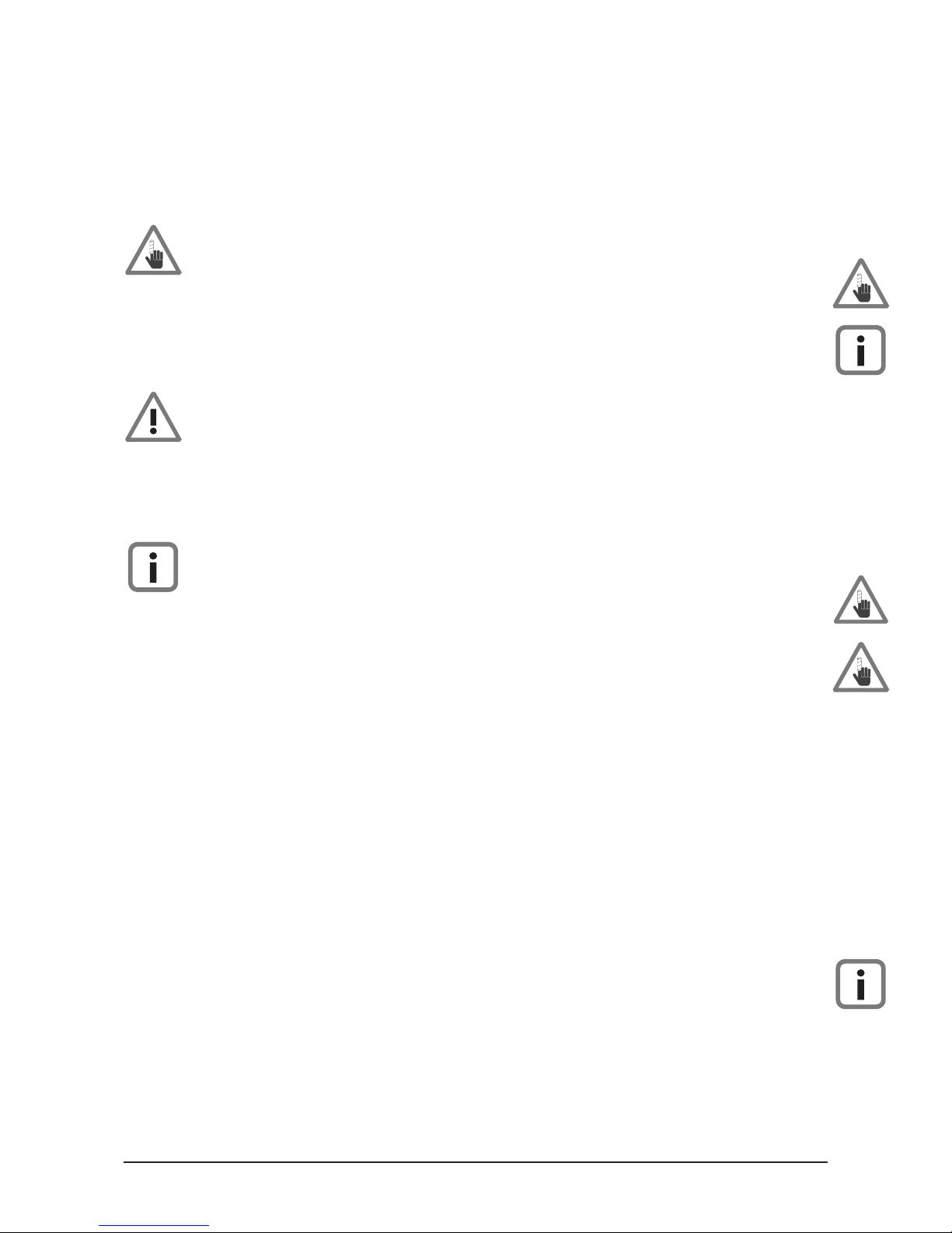
DANGER for danger to the person
Improper electrical installation of the device can lead to
potentially fatal electric shocks as well as other health
hazards.
CAUTION for danger to property
This symbol indicates dangers that can result in damage to
the components or the function of the control.
NOTE for additional information
This symbol indicates practical advice and tricks of the
trade which will be useful for installing and operating the
control.
2.1 Installer’s Qualifications
●
Setting up, installation and commissioning of the
SUNGO S must be carried out by a qualified installer.
●
Please ensure that you comply with national and local
regulations.
●
Please note that if a complaint is made, the guarantee is
only valid if the correct commissioning has been certi
-
fied by a qualified person in the commissioning report.
2.2 Use and Application
Function
●
Controlling solar thermal systems through the selection
of applicable control patterns and additional functions
to adaptthe control forthe required operation of the hy
-
draulic system.
●
The control is certified for use in dry rooms only.
●
The control can either be integrated into the solar circu
-
lation unit or it can be mounted on the wall.
Limitations of use
●
The control‘s suitability should be checked before oper
ation commencesif it is used for any other purpose than
for control‘s suitability solar thermal systems. If you are
unsure you must check withthe serviceof Wagner & Co.
●
The use of the control for non-specified operation re
sults in a lapse of the guarantee.
2.3 Guidelines for Installation and
Operation
●
Because Triacs carry 230V current at the case, the mains
must be disconnected while any installation and wiring
work is carried out.
●
The mains must beconnected to thecontrolvia an exter
nal ON/OFF switch outsidethesolar circulation unit.This
is alsonecessary inorder to be able to activate the“Spe
cial Function” menu through ON and OFF switching.
●
Operating temperatures above 50 °C are not permissi
ble for the control.
●
LCD display panels are designed in such a way that a
specific reading position isrequired.When installing the
solar circulation unit be careful to place the display so
that it is at eye level or slightly higher. This way you can
ensure optimal display contrast (for SUNGO S and SL).
●
The base of the control is divided into a low voltage sec
tion and a 230 V section by a crosspiece. Make sure that
you do not confuse these.
● Automatic mode is the default operation mode of the
control. Manual mode is only used for testing the different components like thepumpand two/three-way valve.
● The system must not be operated if damage to the con-
trol, the wiring or the mains is detected.
● The control is fitted with a low-current fuse.
● Collectors and pipe work becomevery hot duringsunny
periods. There is a risk of scalding when fitting the collector temperature sensor.
3. Installation
3.1 Installation of the Case
Open the casing
●
You require no tools to open the control. The lid snaps
into thelower half. Youcan dislodge and lift upthe lid by
pulling gently on the side clips.
●
The lid arrests automatically when fully opened to allow
for comfortable mounting and wiring.
Wall mounting
●
Using the supplied drilling template drill out the fixing
holes for the control.
●
Mount the control to the wall.
●
Tighten screws only as far as necessary. Over-tightening
may damage the casing!
Page 5

EN-SUNGO-S-BA-0804-1122P200 5
Installation in the Solar Circulation Unit
●
Affix the SUNGO S with the appropriate screws to the
wall mounting bracket of the solar circulation unit.
●
Open up thecable ducts next to thecentrecrosspiece in
the bottom of the control.
●
Remove outer insulation of the cables in such way that
single isolated wires start as they enter the casing from
the bottom.
●
Hold the connectors with one hand while tightening the
screws in order tominimisepressureonthe circuit board
and to avoid tearing the connectors off.
●
Last connection should be to mains.
●
If power is switched on now, 230V AC will be present on
the casing of the triacs.
3.2 Connecting Wires
Layout of the SUNGO S connections
All connectionsaremade to the circuit board atthe bottom
of the control. On the right hand side you will find the con
nections for the sensors (low voltage area) while on the left
hand side you will find the connections for mains and
switching output A1.
General connection rules
●
If flexiblewires are used and the controller is fitted to the
wall, wires must be tied externally in such way that strain
to the controller is avoided.
● In this case you must tin or crimp the wire ends.
● If required PG9 screws can befixed at thefeed-throughs
if the control is mounted to the wall.
230 V mains connection
●
Mains power is connected from outside the connector
via an ON/OFF switch.
If the unit isconnected with a plug toa socket, the switch
can be omitted.
●
The unit is designed to work with 230V AC/50Hz.Please
check that your pump has compatible specifications.
●
All earth wires are connected to the PE-connectors.
●
The neutral terminals (N) are connected electrically.
●
Switch output A1 is a230 V normally opencontact which
is activated via speed-control.
Connecting the temperature sensors
●
The wires for the temperature sensors canbe extended:
Up to 15mlength = 2 x0.5 mm² cable canbeused; upto
50m=2x0.75 mm² cable is necessary.
Forlong connections itisrecommended to use shielded
cable.
Do not connect the shielding at the sensor end,just trim
and isolate!
●
Temperature sensors are without polarity and can be
connected any way.
●
Sensor wires must be installed away from mainscarrying
cables.
Lightning protector module
The SUNGO S is fitted with spike protection on all sensor
terminals. Generally, further protection of the cylinder sen
sors is not required.
Sensor T1 (collector) requires installation of sensor connection box SP2 with excess voltage protection.
Safety fuse
Mains voltage area Safety low voltage area
Mains connector
Switch output A1 connector
Mains microfuse 2A/T
Electronic triac switch
Triac control IC
Transformer
for circuit voltage 12 V
Ribbon cable plug
for display circuit
Sensors T1-T3 connectors
Earth potential connector
Figure 2 SUNGO S circuit board components.
Page 6

6 EN-SUNGO-S-BA-0804-1122P200
4. Operation
4.1 Display and Buttons
!
dT min max start stop
R
h
R
ok?
88888
°C %
x
Manual operation men
u
Special functions menu
Balance or
start / stop values
Units
Tank temperature,
upper half
Confirm /
save icon
System error
Settings menu
Information menu
Temperature difference
Number display for
temp. or sensor errors
Collector temperature
Reset symbol
Tank temperature, lower half
Pump ON
Pump OFF
Output A1
Figure 3 Connections.
Safety fuse
T1, collector sensor
T2, tank sensor, lower half
T3, tank sensor, upper half
Mains, PE
Solar circulation pump, PE
Mains, phase (L)
Mains, neutral (N)
Solar circulation pump, phase (L1)
Solar circulation pump, zero (N1)
Mains voltage area
Safety low voltage area
Page 7

EN-SUNGO-S-BA-0804-1122P200 7
Horizontal operating level
Vertical
operating level
Set values
Settings menu
as an example
Temperature limitation tank, bottom
Switch-on difference T1-T2, solar
Switch-off difference T1-T2, solar
Minimum temperature source
Set point temperature difference, speed control, solar
Solar circulation pump
Maximum speed solar circulation pump (SECUSOL)
System filling time (SECUSOL)
dT max
__K
dT min
__K
__°C
T max
__°C
T min
T start
__
d max
__
d min
__
__K
dT
Save
v
alue
Activate
save function
Decrease
value
Increase
value
Ý
Ý
Ý
Activate
value
Ý
Page 8

8 EN-SUNGO-S-BA-0804-1122P200
4.2 Information Menu
Information menu
Menu item Description Display
Collector temperature; Current value °C
Collector temperature; Balance value; minimum, resettable °C
Collector temperature; Balance value; maximum, resettable °C
Tank temperature, lower half; Current value °C
Tank temperature, lower half; Balance value; minimum, resettable °C
Tank temperature, lower half; Balance value; maximum, resettable °C
Tank temperature, upper half
1
; Current value °C
Operating hours, total; Current value h
Reset operating hours since last reset
Balance value, display, resettable;
h
Pump symbol idle: Function display
Temperature difference between collector and tank
is smaller than switch-on difference (solar circulation pump off).
—
Pump symbol active: Function display
Temperature difference between collector and tank
is higher than switch-on difference (solar circulation pump on).
—
1
Sensor T3 (tank, upper half) is simply a measuring sensor, therefore it is not monitored by the sensor control.
4.3 Settings Menu
Settings menu
Menu item Description Range Base value
Temperature limitation tank, lower half 15 - 90 °C 85 °C
Switch-on difference between collector and tank 3 - 40 K 10 K
Switch-off difference between collector and tank 2 - 35 K 3 K
Minimum temperature where analysis of switch-on difference starts 5 - 90 °C 10 °C
Set point temperature difference the speed control adjusts to 2 - 50 K 10 K
Minimum speed of the solar circulation pump
10% increments
30-100% 30%
Maximum speed of the solar circulation pump
SECUSOL only!
30-100% 100%
Charge time (s) of the solar heating system with speed 100 %; in 10 s increments
SECUSOL only!
20 - 360 s 60 s
min
__°C
__°C
__°C
__°C
__°C
__°C
__°C
__h
min
max
max
__h
R
dT max
__K
dT min
__K
__°C
T max
__°C
T min
T start
__
d max
__
d min
__
__K
dT
Page 9

EN-SUNGO-S-BA-0804-1122P200 9
4.4 Manual Operation Menu
Manual operation menu
Menu item Description Range Base value
Off = 0/On = 1
Manual on/off via output A1 (solar circulation pump)
0-1 0
Activation of manual operation lag time in automatic mode 0 - 600 min 0 min
4.5 Special Functions Menu
Within the first minute after switching on the controller,select the “Special Functions“ menu in order to activate it, so that
the individual parameters can be changed.
After leavingit,the menuremains active forone minute.Afterwards the parameters can only beviewed butnot changed.
In order to change the functions again, it is necessary to disconnect the controller from the mains again.
Special functions menu
Menu
item
Application Description Range
Base value
0 System choice
0 - 1: Standard single-tank system
0 - 2: Cannot be selected !
0 - 3: SECUSOL system (see SECUSOL instructions for further info)
1or3 1
1
System
Protection
Off = 0/On = 1
Activation of system protection.
Cannot be activated with SECUSOL!
0or1 1
2 System protection start temperature 115 - 200 °C 135 °C
3
Collector Cooling
Off = 0/On = 1
Activation of collector cooling.
Cannot be activated with SECUSOL!
0or1 1
4 Collector cooling start temperature 100 - 150 °C 110 °C
5
Tank Cooling
Off = 0/On = 1
Activation of tank cooling. Only possible with collector cooling.
Cannot be activated with SECUSOL!
0or1 0
6 Switch-off temperature 30 - 90 °C 60 °C
7-10 Menu items 7-10 are not available for the SUNGO S controller
11
Tube collector
function
Off = 0/On = 1
Activation of vacuum tube collector function
0or1 0
12 Run time of solar circulation pump from reaching the switch-on value 1 - 60 s 15 s
13 Switch-on value for temperature increase at sensor T1 (collector) 1.0 - 5.0 K 1.0 K
__
T stop
Only expert personnel
should edit the special functions menu.
Incorrect settings may adversely affect the solar heating
system.
Page 10

10 EN-SUNGO-S-BA-0804-1122P200
4.6 Service – System Messages
Display of system information
Display Description Correction
System Messages
All system messages are displayed with a blinking caution symbol.
In case of sensor errors the sensor in question is also marked with short circuit or interruption symbols.
Interruption
Displayed sensor or line connection interrupted
/ defunct.
●
Check the resistance value of the sensor and
compare to the resistance table.
●
Check all contact points up to the sensor.
Short circuit
There is a short circuit of the sensor on the
display, the line or the sensor input on the
controller.
dT too high
A fixed value of 20 K is added to the
temperature difference between collector (T1)
and tank sensor (T2). The message is displayed
if after 30 minutes the total temperature
difference has not been reduced.
●
Check pump/pump connections/wiring.
●
Check system for air, and vent if required.
●
Check sensors/sensor lines and change sensor if
required.
4.7 Service – Sensor Control
Resistance values for Pt1000-sensors in relation to the temperature
-10°C 0°C 10°C 20°C 30°C 40°C 50°C 60°C 70°C 80°C 90°C 100°C 110°C
961 Ω 1000 Ω 1039 Ω 1078 Ω 1117 Ω 1155 Ω 1194 Ω 1232 Ω 1271 Ω 1309 Ω 1347 Ω 1385 Ω 1423 Ω
The working condition of the sensor can be checked with this table and an Ohm meter.
!
Blinking
!
Blinking
!
Blinking
°C
!
Blinking
°C
Page 11

EN-SUNGO-S-BA-0804-1122P200 11
5. Application examples
5.1 Standard Single-Tank System
Figure 4 Standard single-tank system controlled by SUNGO S.
P3
P2
Ta
A1
T2
T3
T1
CIRCO
T2
ECOplus
Ttw
T3
P1
T1
BWM
Hot water
Cold water
Oil or gas
boiler
Heating circuit
Collector field
T1: Collector sensor
T2: Tank sensor,lower half
T3: Tank sensor,upper half
P1: Solar circulation pump
P2: Heating circuit pump
P3: Tank charging pump
Ttw: Hot water sensor (heatingcontrol)
BWM: Thermostatic mixing valve
Page 12

Figure 5 SECUSOL system controlled by SUNGO S.
5.2 SECUSOL System
T3
A1
T2 T1
SECUSOL
Ta
P3
P2
BWM
T1
T2
T3
Ttw
P1
Hot water
Cold water
Heating circuit
Collector field (EURO C22)
Oil or gas
boiler
T1: Collector sensor
T2: Tanksensor,lower half
T3: Tank1sensor,upper half (optional)
P1: Solar circulationpump
P2: Heating circuitpump
P3: Tank charging pump
Ttw: Hot water sensor(heatingcontrol)
BWM: Thermostatic mixing valve
Subject to modifications, errors excepted. · ©Wagner & Co, 2008 · www.wagner-solar.com
12 WAGNER & CO · Zimmermannstraße 12 · D-35091 Cölbe/Marburg ·
☎
+49 6421 80 07-0 · Fax 8007-22
 Loading...