

Page 1
TECHNICAL INFORMATION / INSTALLATION INSTRUCTIONS
o
Wagner & C
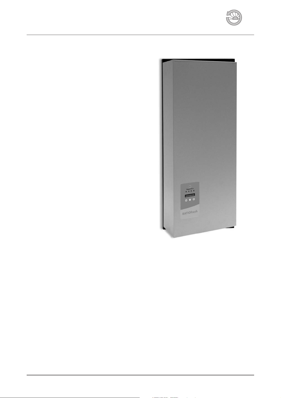
RATIOfresh Freshwater Station 250/400
Hygienic Water Heating
A continuous flow process is used to heat potable water
quickly and on demand to a preset temperature.
Excellent Performance
The RATIOfresh 250 unit delivers hot water at up to 25 l/
min. Thelarger station RATIOfresh 400 even reaches a tap
ping capacity of 40 l/min and thus is suitable for multi-fam
ily homes with up to 20 individual apartments.
Functional Design
A modern powder-coated metal casing houses all compo
nents in a compact design.
Adaptive Microprocessor Controlling
The microprocessor “learns“ the water withdrawal patterns
of users.This meansthefreely selectable hotwatertemper
ature can be maintained precisely even with fluctuating
flow or inlet temperatures within the primary circuit. This
also offers various options of regulating hot water
circulation.
-
-
-
-
Easy Assembly and Maintenance
The station is suitable for mounting on the wall or the storage tank (in conjunction withall RATIO buffer cylinders and
the additionally available tank expansion kit). Flat sealing
connections simplify assembly and installation aswell as all
service tasks. After the hydraulic integration, the ready-toplug-in station can beoperatedimmediatelyasdelivered.
Numerous Application Options
The freshwater station can be combined with almost any
heat source. Oil, gas, wood logs and pellet boilers are as
suitable as asolar installation orlocal or districtheating dis
tribution systems. All ittakesis a buffer cylinder whosether
mal stratification is supported by minimal return tempera
tures within the primary circuit.
Protection from Legionella Pneumophila Bacteria
If required, the hot water and the circulation piping net
work can be thermally disinfected. Time, temperature, and
duration of the disinfection process are individually
adjustable.
Content
1. Technical Information .................2
1.1 TechnicalData ......................2
1.2 Scope of Delivery ....................3
1.3 Accessories .......................3
2. Safety Information ...................6
2.1 Operator Qualifications ................6
2.2 Intended Use ......................6
2.3 Standards andGuidelines ...............7
2.4 Installation Recommendations ............7
-
-
-
Figure 1 RATIOfresh Freshwater Station 250/400.
3. Installation ........................8
-
3.1 Prior to theInstallation .................8
3.2 Wall Mounting ......................8
3.3 Storage Tank Mounting ................8
3.4 Connecting Potable Water ...............9
3.5 Connecting Circulation .................9
3.6 Installing thePrimaryCircuit .............10
3.7 Switching thePrimaryReturn Flow ..........11
3.8 Connecting theController ..............11
3.9 Closing theHousing..................11
4. ControllerOperation .................13
4.1 Controller Displays ..................13
4.2 Controller Settings...................13
4.3 Controller SettingTables ...............14
5. Initial Startup......................19
6. Notes for Operators ..................20
7. Maintenance and Care ................22
8. Troubleshooting....................23
9. System Solutions – Example .............27
Solar Thermal / Solar Cylinder EN-RATIOfresh-250-400_TI-MA-0809-11214900 1
Page 2

1. Technical Information
1.1 Technical Data
Table 1 Technical Data
Feature RATIOfresh 250
Variation Copper soldered heat exchanger Stainless steel soldered heat exchanger
Order no. 150 300 65 150 301 77
Nominal tapping capacity
10 °C → 45 °C (sec.)
10 °C → 60 °C (sec.)
Coefficient of performance (NL)
10 °C → 45 °C (sec.), 82 °C (prim.) acc. to DIN 4708 T3
10 °C → 60 °C (sec.), 85 °C (prim.)
10 °C → 60 °C (sec.), 75 °C (prim.)
Nominal hot water temperature 25 – 70 °C
Circulation return 5 – 70 °C/5–25K
Pressure loss, Dp secondary < 370 mbar (with 25 l/min)
Voltage supply 230V/50Hz
Fuses
Dimensions of housing (HxWxD) 940x350x181mm
Color (powder-coated)
Max. permissible pressure 6 bar (primary), 10 bar (secondary)
Max. permissible temperature 95 °C (primary and secondary)
Capacity of water space 1.1 l (primary) / 1.2 l (secondary)
Max. electrical power consumption / standby
operation mode
Protection class IP 44
Weight 26 kg
25 l/min
61 kW
87 kW
=13
N
L
N
=11
L
=7
N
L
Operating voltage 230 V, control fuse 100 mAT / 250 V, power fuse 2 AT/250 V.
To replace internal fuses, de-energize the device, remove the screws on the
controller, and lift off cover (fig. 8, 9, 10).
Upper section: RAL 7035 (light gray)
Bottom section: RAL 7021 (black-gray)
2 x 200 W (when connecting two pumps) / 0.6 W
2 EN-RATIOfresh-250-400_TI-MA-0809-11214900
Page 3
Table 2 Technical Data
Feature RATIOfresh 250
Variation Copper soldered heat exchanger Stainless steel soldered heat exchanger
Order no. 150 300 66 150 301 78
Nominal tapping capacity
10 °C → 45 °C (sec.)
10 °C → 60 °C (sec.)
Coefficient of performance (NL)
10 °C → 45 °C (sec.), 82 °C (prim.) acc. to DIN 4708 T3
10 °C → 60 °C (sec.), 85 °C (prim.)
10 °C → 60 °C (sec.), 75 °C (prim.)
Nominal hot water temperature 25 – 70 °C
Circulation return 5 – 70 °C/5–25K
Pressure loss, Dp secondary < 490 mbar (with 40 l/min)
Voltage supply 230V/50Hz
Fuses
Dimensions of housing (HxWxD) 940x350x181mm
Color (powder-coated)
Max. permissible pressure 6 bar (primary), 10 bar (secondary)
Max. permissible temperature 95 °C (primary and secondary)
Capacity of water space 1.6 l (primary) / 1.2 l (secondary)
Max. electrical power consumption / standby
operation mode
Protection class IP 44
Weight 28 kg
40 l/min
98 kW
139 kW
= 19,5
N
L
N
=17
L
=11
N
L
Operating voltage 230 V, control fuse 100 mAT / 250 V, power fuse 2 AT/250 V.
To replace internal fuses, de-energize the device, remove the screws on the
controller, and lift off cover (fig. 8, 9, 10).
Upper section: RAL 7035 (light gray)
Bottom section: RAL 7021 (black-gray)
2 x 200 W (when connecting two pumps) / 0.6 W
1.2 Scope of Delivery
Table 3 Delivery Scope
Freshwater station, ready for plug-and-play, 4 dowel sets for wall
mounting; 4 solder connection sets LT 22-1; installation
instruction
1.3 Accessories
Table 4 Accessories
Item Order no.
Solder connection set
LT 28.1 ¼“, swivel nut,
gasket and solder connection 22mm
Threaded connection set
GT 1 ¼“, swivel nut,
gasket and threaded connection
RATIOfresh RS 232 PC interface cable 150 400 22
Cylinder mounting kit for CIRCO 139 000 28
Motor actuated 3 way valve 1“ M 160 101 44
Motor actuated 2way ball valve 819 201 33
139 000 44
130 100 88
EN-RATIOfresh-250-400_TI-MA-0809-11214900 3
Page 4
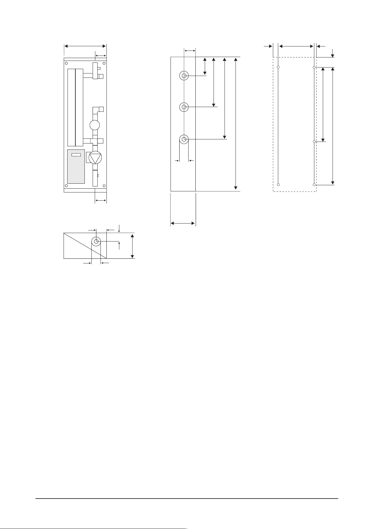
Frontal view
350
4 Primary
flow
80
7 Hot water
Side view
110
100
240
Drill pattern
64
254
32
70
2-Heat ex
changer
6 Cold water
9 Single-jet meter
570
940
8 Circulation
3 Circulation pump
ø55
1 Controller
10 Housing
5 Primary
85
return
Top/bottom view
181
80
57
181
ø55
Figure 2 RATIOfresh freshwater station viewed sectionally, with dimensions and drilling template.
521
827
4 EN-RATIOfresh-250-400_TI-MA-0809-11214900
Page 5
Housing cover
11
12
18
10
Top section of housing
4
7
13
6
9
2
14
16
Wagner &Co
17
1
15
19
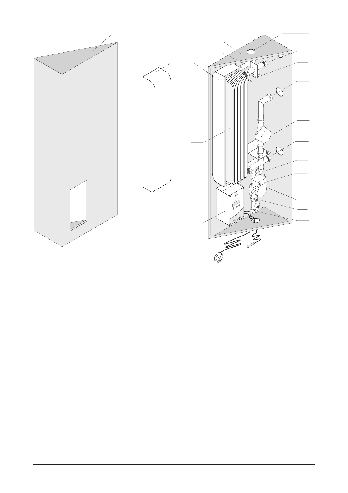
Figure 3 Cross-section of RATIOfresh freshwater station with dimensions and drill hole pattern (page 4)
1 Adaptive microprocessor controlto regulatehotwater and circulation,display2x16 characters,plasticfoil keypad with3 keysand 4 LED,2 power
outputs, 3temperaturesensors and 2 immersionsleeves made from chrome-plated brass; 2 Plate heatexchanger made from stainless steel,cop
per-soldered, flat-sealing connection T1" (OT)–quickly disassembled formaintenance,specially embossed platestructuretoavoid lime deposits;
3 Circulation pump in primary return, especially energy-saving design, easy to service due to flat-sealing integration;
4 Primary flow connection T 1" (OT,flat-sealing) made from brass, with shut-off valve; 5 Primary return connection T1" (OT, flat-sealing) made from
brass, with pump shut-offslider incl. backflow preventer; 6 Cold watersupplyconnection T 1" (OT, flat-sealing) made frombrass ; 7 Hot wateroutlet
connection T 1" (OT, flat-sealing) made from brass; 8 Circulation return connection option T ½" (IT) closed with plug; 9 Single-jet meter – brass,
chrome-plated, connections ¾" (OT,flat-sealing),QN 2.5 m³/h; 10 Bottom section of housing made from powder-coated sheet steel with keyhole
drills for wall mounting; 11 Housing cover made from powder-coated sheet steel, removable; 12 EPP shell insulation (expanded polystyrene) for
plate heat exchanger; 13 Temperature sensor hot water; 14 Temperature sensor circulation return; 15 Temperature sensor storage cylinder; 16
Power switch to select pump output level; 17 Backflow preventer (in ball valve); 18 Temperature sensor primary; 19 Mains plug.
8
3
5
-
EN-RATIOfresh-250-400_TI-MA-0809-11214900 5
Page 6

2. Safety Information
The following safety information is intended to protect you
from hazards and dangers that may suddenly occur when
the device is handled incorrectly, either deliberately or un
knowingly. We differentiate between general safety infor
mation, explained onthis page, and special safetyinforma
tion, which is listed throughout the text of this manual. The
following symbols are important!
DANGER – possibility of personal injury
The following may occur during assembly or installation:
hazardous electrical shock, scalding, bruising/contusions,
and other adversehealth effects. Please complywiththe in
structions marked with this symbol in the documentation.
CAUTION – possibility of property damage
This symbol indicates hazards that may result in damage to
components or a significant reduction of the functionality
of the system. Please follow the described assembly steps
and comply with the sequence of these steps.
NOTE – additional information
This symbol indicates useful notes, tips to make work
easier,and other information that may help you with the installation or operation.
2.1 Operator Qualifications
station is designed insuch a way that the lowestpossiblere
turn temperatures are reached, which exhibit only a minor
difference to the cold water temperature.
Thermal Disinfection
The Legionella Pneumophila Bacteria protection function
can be used to disinfectthe entire hotwater and circulation
piping network thermally and during freely selectable
times (day or week program). You choose between once
per week (Mon-Sun) or daily. This function serves to pre
vent the formation of bacteria and viruses in the potable
water network.
The station uses an external relay output to activate the
buffer storage auxiliary or backup heating if the required
primary temperature (= disinfection temp. + hysteresis
) is not detected by the sensor T
dT
NH
picts “DISINFECTION.” If the required temperature exists
within the primary circuit (data logging with the tempera
ture sensor “T
starts. The freely selectable disinfection temperature (e.g.
65 °C) ismaintained across asettable time duration (e.g. 20
min) and across all flooded hot water andcirculation pipes.
Unexpected malfunctions during the disinfection phase
are indicated to theuser in plaintextand additionally witha
visual signal (LED light, fig. 10, no. 4).
Potable water hygienists recommend a material tempera
ture of 70 °C or higher for a duration of at least3 minutes to
disinfect the piping network. The disinfectiontemperature,
however, should be a few degrees higher or the disinfection time somewhat longer to ensure proper disinfection
occurs. Do not forgetto raise the branchlines to the hotwater tapping points to the required temperatures by withdrawing water several times for several minutes.
Before activating the disinfection function, check whether
the hot water or circulation network can sustain such high
temperature stress (e.g. damaging galvanized steel pipes)
and whether the carbon hardness of the potable water is
within an acceptable range.
The hot water users are at risk of scalding injuries while the
disinfection program is running. The disinfection should
therefore be carried out at night.
”), the thermal disinfection program
buffer
. The display de
buffer
-
-
-
-
-
All tasks and activities involving the transport, installation,
as well as operation and servicing must be performed by
qualified technicalpersonnel. We do not assume responsi
bility or liabilityfordamages resulting from noncompliance
with these instructions.
2.2 Intended Use
Function
Heated water from a storage tank is used with a plate heat
exchanger to prepare hot water with a constant tempera
ture.Thecooled down return water is layeredintothe lower
section of the storage tank.
This is controlled demand-dependent. Only when potable
water is withdrawn and detected by the single-jet meter,
the circulation pump feeds the exchanger with a variable
hot water volumestream from the storagetank so thata de
fined tapping temperature is maintained.
The return temperature is the resultof the storagetank tem
perature, the pump speed, and the plate heat exchanger
design. The heat exchanger of the RATIOfresh freshwater
6 EN-RATIOfresh-250-400_TI-MA-0809-11214900
Circulation
The temperature difference is calculated from the circula
tion flow and return temperature and compared with the
preset nominal difference. If the temperature difference is
too small, the control detects an oversupply of the circula
tion and reduces the output of the circulation pump based
on the deviation. If the temperature difference is too great,
the control increases the output of the circulation pump
based on the deviation. The mass flow is then varied
through a pulsed modulation of the pump output. If an ad
justable return temperature is exceeded, the controller
switches the pump off.
-
-
-
-
-
-
Page 7

Standby Temperature Control
The RATIOfresh freshwater station is also equipped with a
standby temperature control in addition to the circulation
function. The control activates the primary pump and sup
plies the station with hot water to maintain the preset
standby temperature at the primary flow outlet port re
gardless of a withdrawal of hot water.
This function serves to preheat the plate heat exchanger;
this means that hot water is thus much more quickly avail
able at the desired nominal temperature in case water is
withdrawn. This function also protects from frost if the
standby temperature is set to a lower value of 10 °C. The
standby temperature control is only activated if the cylin
der temperature is sufficiently high.
2.3 Standards and Guidelines
The following standards and guidelines must be observed
and complied with when installing hydraulics and/or per
forming electrical wiring: IEC 364 or CENELEC HD 384,
DIN VDE 0100 and IEC-Report 664, DIN VDE 0110 and na
tional accident prevention rules and regulations, as well as
VDE 0100, VDE 0160 (EN 50178), VDE 0113 (EN 60204),
and local rules and specifications of your energy provider
or utility company.
Specifications outlined by DVGW W551 concerning pro
tection from the Legionella pneumophila bacteria must be
observed for multi-family home installations. A circulation
must be operated between hot water heater and tapping
point for potable water volumes greater than 3 liters. The
hot water outlet temperature of the RATIOfresh station
must always be set to ≥ 60 °C.
2.4 Installation Recommendations
Connecting the Circulation
The freshwater station RATIOfresh is designed to be con
nected toa circulation line. The circulation pumpmust be a
commercially available stepped wet pump. E-pumps or
pumps with integrated motor protection or ON/OFF
switching electronics may not be operated.
-
Connecting the Primary Circuit
The pipingof the primarycircuit should be as short as pos
sible to achieve the rapid heating of the heat exchanger
when water is tapped. The max. permissible pressure loss
within the primary circuit may not be exceeded when lines
are longer.
A bleeder is to be installed at the highest point of the pri
mary circuit. The primary flow should be withdrawn at the
hottest pointof the buffer storagetank, and the primary re
turn should bereturnedas close tothe bottom ofthe buffer
storage tank as possible.
Gravity circulations may occur depending on the length,
design, and insulation state of the primary circuit.This con
tinuously withdraws energy from the standby section of the
buffer cylinder.
A gravity brake with low admission pressure must be in
stalled on-site in addition.
Thermal Disinfection / Protection from Legionella
Pneumophila Bacteria
Please note that the “Disinfection” function only can be
used as intended if the cylinder temperature sensor can
correctly measure the derivative temperature within the
connected auxiliary heating range. The sensor should thus
be attached 10 cm below the actual tapping point on the
buffer cylinder (on the tank wall as depicted in fig. 7).
Please also notethat increased temperatures within the hot
water networkand associated pipes pose a risk of scalding
injuries while the disinfection program is running!
-
-
-
-
-
-
The tank must be installed in a frost-free room with short
lines to the consumer.
De-energize the control unit as outlined by the manual be
fore working on the pump or the control unit. Controller
and pump carry electricity even if the controller switches
the pump off!
Cold and Hot Water Line
A safety valve (cf.fig. 5) is required in the cold water supply
line as specified by DIN 4753 T1. Amin.thread diameter of
DN 15 must be selected for a heating output of max. 75 kW.
Thesafety valve can beomittedonly if atypeapprovedflow
monitor limits the water temperature to 95 °C. The valve
must be designed for a blowing-off pressure that corre
sponds with the permissible working overpressure.In case
of 10 bar and higher waterline pressures, install a pressure
reducer behind the water meter. When heating the fresh
water station without watertap,wateris dripping out offthe
safety valve. Use a siphon funnel to catch and dispose off
this water.
Do not install a shut-off between safety valve and freshwa
ter station. A drain valve should be installed for mainte
nance and service tasks. The functionality of the safety
valve must be checked regularly in accordance with DIN
4753.Theexhaust vent may neverbeclosed or restricted. A
corresponding water filter meeting current technology
standards is to beinstalledinto the cold watersupplyline.
Protection from Corrosion and Lime Buildup
All water-conducting parts are basically subject to corro
sion and lime buildup, especially if temperatures exceed
60 °C and with aggressive water. Hot water temperatures
thus should never exceed 60 °C. Significant lime deposits
are not expected with carbonate hardness below approx.
10° dH and temperatures less than 60 °C. If your potable
water is harder than this, we recommend on-site lime
buildup reducing measures. If the plate heat exchanger
must be decalcified on a regular basis, irrigation cocks (fig.
6) should be installed during the system assembly.
The plate heat exchanger of your freshwater station is
made from copper soldered stainless steel plates. Steel
pipes may thus not be used in the flow direction (towards
the freshwater station) since copper is water soluble in
minute particles and causes pitting when deposited on
steel.
Water with low hydrocarbon content and high portion of
neutral salts (e.g. soft water containing chloride) can cause
dezincification of the installed brass elements.
-
-
-
EN-RATIOfresh-250-400_TI-MA-0809-11214900 7
Page 8
3. Installation
4
3.1 Prior to the Installation
Before assembly, please compare thedelivered compo
●
nents with the parts list in table 3.
You need the following tools: drill, stone drill (12 mm),
●
voltage meter, screwdriver, folding meter-rule, wrench
size 10, monkey wrench, ratchet with size 13 socket.
Materials/components needed on-site: sets of union
●
connectors to connect primary and potable water cir
cuit, a safety subassembly to install into potable water
network if needed, a circulation pump if needed, pipe
material, and insulation material.
Open the RATIOfresh freshwater station as depicted in
●
fig. 8 byremoving the housing coverin the lowersection
from the lower part and lift out off the snap-in groove.
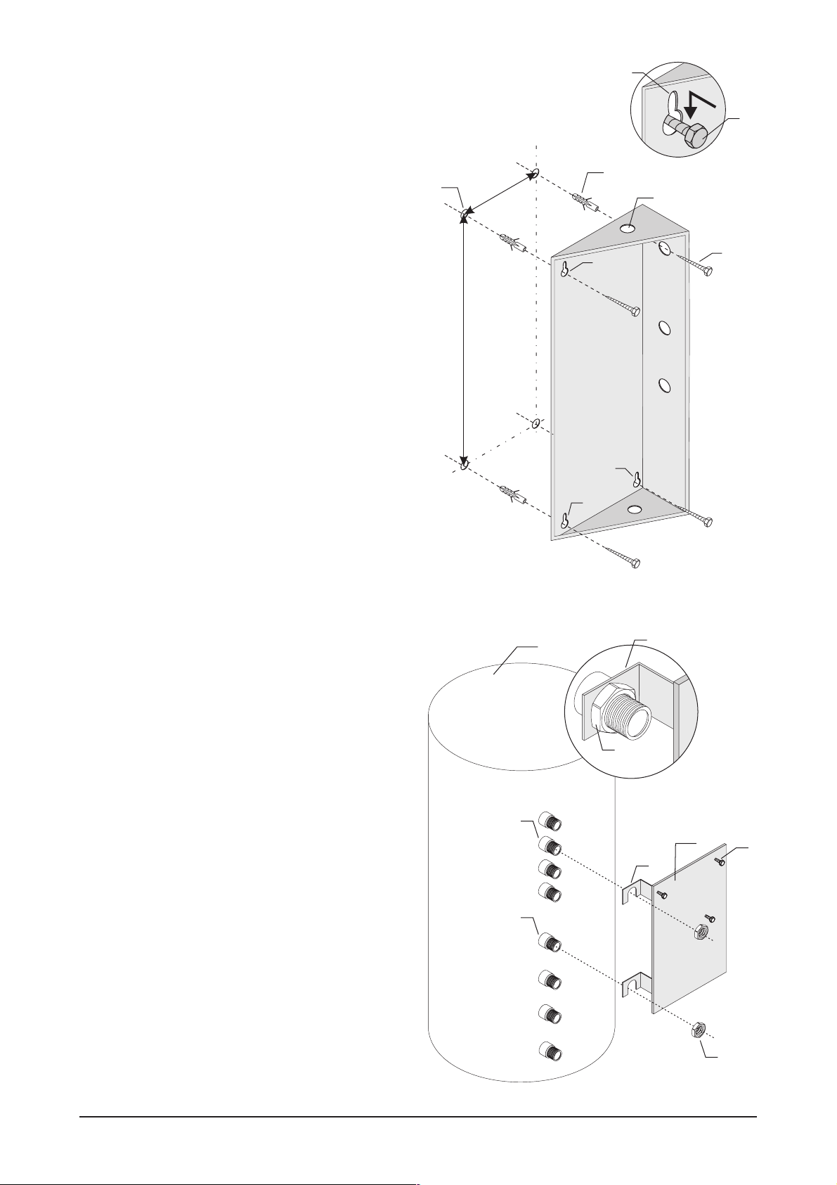
3.2 Wall Mounting (fig. 4)
Transfer the hole pattern to thewallas depicted in fig.4.
●
Drill holes (1) with a 12-mm stone drill and insert in
●
cluded plugs (2).
Insert screws (3) to adistance of 1 cmand insert housing
●
(4) into keyholes (5) and attach screws.
Tighten screws (3) firmly.
●
3
-
1
254
2
4
-
5
827
3
-
5
5
3.3 Storage Tank Mounting (fig. 5)
The RATIOfresh freshwater station is suitable for mounting
directly on all buffer cylinders (RATIO-H series) using the
additionally available tank expansion kit (cf. accessories,
table 4):
● Remove the insulation of the RATIO-H (1) cylinder and
snap the mounting plate (3) with the U-shaped ends (4)
into the second (2)andfifthconnection (5) from the top.
●
Screw down the mounting plate withthe included 1 1/2"
flat swivel nuts (6).
●
Then screw the included 3 hexagonal carriage bolts (7)
halfway into the mounting plate, attach lower part of
housing with keyhole drill holes (fig. 4) and tighten with
the carriage bolts (7).
Figure 4 Wall mounting
1 Holes; 2 Plugs; 3 Screws; 4 Bottom section of housing ;
5 Keyholes.
1
2
5
4
6
4
3
7
Figure 5 Tank mounting
1 RATIO-H cylinder; 2 Second connection from top;
3 Mounting plate; 4 Bracket; 5 Fifth connection from top;
6 1¼" flat swivel nut; 7 Hexagonal carriage bolts.
8 EN-RATIOfresh-250-400_TI-MA-0809-11214900
6
Page 9
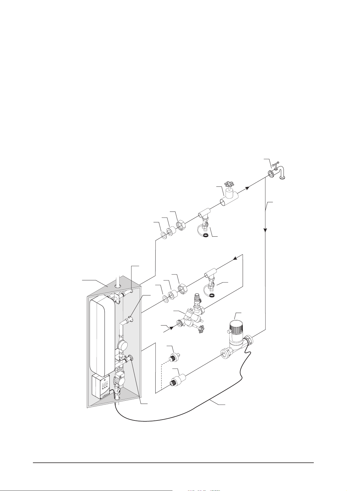
3.4 Connecting Potable Water (fig. 6)
Cold and hot water connections must be connected to the
freshwater station in accordance with the rules and regula
tions issued by the local water utility or water provider. We
recommend connecting to the potable water network in
the manner illustrated in fig. 6.
A safety subassembly (3) with safety, shut-off, and check
●
valve must be installed in the cold water supply (2) in
acc. with DIN 1988. Make sure there is no shut-off be
tween the RATIOfresh station (1) and the safety sub
assembly (3). To connect the piping to the cold water
supply (7) of the station, please use the connection sets
with 1" swivel nuts (4), soldered connection 22 mm (5),
and flat seal (6) or threaded connection sets as an alter
native, both available as additional accessories.
The hot water outlet of the station (8)mustbe connected
●
to thehot water network with soldered or threaded con
nection sets and well insulated as well. Do not forget flat
seals (6)!
Potable water with a high content of lime may require
●
that the heat exchanger is flushed regularly. This re
quires installing irrigation cocks (9) and (10) into the
cold andhot water lines in closeproximity to thestation!
After irrigation cock (10) in the hot water line, an addi
tional shut-off cock(11)isneeded for flushing thepipes.
5
6
3.5 Connecting Circulation
(Optional, fig. 6)
DVGW 551 specifies a circulation element or system in
larger hot water networks. The circulation return (21) must
be installed directly before tapping point (22).The circula
tion pump (23) is supplied with voltage and controlled by
the controller. Chapter 3.7 provides information about the
correct connection of the power cable (24). Please note
that a backflow preventer (integrated inthefigureof the cir
culation pump) must be installed in the circulation line.
-
Remove the 1/2" plug (26) at the circulation return con
●
nection of the station (25) and attach the circulation re
turn line asperconnection diagram.Use a 1/2" threaded
connection (27).
-
-
22
-
-
4
11
21
-
-
-
-
10
8
4
25
5
6
7
3
2
KW
26
27
1/2 AG
9
23
24
1
Wagner& Co
Figure 6 Potable water connection
1 Bottom section of housing; 2 Cold water supply; 3 Safety subassembly ; 4 1" swivel nut ; 5 22-mm soldered connection; 6 Flat seal;
7 Cold water supply; 8 Hot water outlet; 9 Irrigation cock; 10 Irrigation cock; 11 Shutoff valve; 21 Circulation return;
22 Tapping point; 23 Circulation pump; 24 Connection cable to circulation pump; 25 Circulation return connection;
26 ½" plug; 27 ½" threaded sleeve.
EN-RATIOfresh-250-400_TI-MA-0809-11214900 9
Page 10

3.6 Installing the Primary Circuit (fig. 7)
In order for the RATIOfresh freshwater station to yield the
desired output, it must be suppliedwith a sufficient volume
of hot water either from a buffer storage tank or a district
heating system. Table 14 lists the required primary flow
temperatures.
The primary circuit may never be serviced by another
pump even only temporarily!
Route primary flowline(1) from the hotstorage tank sec
●
tion to the RATIOfresh-freshwater station and connect
with soldered orthreadedconnection sets. At theRATIO
cylinder use 18-1½" connection sets with swivel nut (4),
soldered or threaded connection (3) and flat seal (2),
and connection sets22-1¼" with swivelnut (7), soldered
or threaded connection(6)and flat seal(5)at the station.
Install a bleederif lines in theprimaryflow are installed in
an upward direction!
Connect the primary return line (8) and route to the cor
●
responding storage tank connection that matches the
temperature level. Table14 lists the return temperatures
of the station in dependency of the operating condi
tions.
Routecableofthetemperaturesensor(9) marked
●
” from the freshwater station along theprimary flow
“T
prim
and attach sensor in the aux. heating section of the
buffer cylinder approx. 10 cm below the actual tapping
point of the primary flow. Use the uppermost position of
-
the connector block (10) at the RATIO buffer cylinder.
The sensor must correctly detect thecylinder temperature.
Check the correct position of the sensors after the initial
startup!
-
-
1
2
3
4
7
6
5
Wagner&Co
5
6
7
2
3
4
8
10 cm
9
9
10
10
Figure 7 Primary circuit installation
6-1 Primary flowline; 6-2 Flat seal; 6-3 Soldered or threaded connection; 6-4 Swivel nut; 6-5 Flat seal; 6-6 Soldered or threaded union; 6-7 Swivel
nut; 6-8 Primary return line; 6-9 Temperature sensor T
10 EN-RATIOfresh-250-400_TI-MA-0809-11214900
; 6-10 Connector block.
buffer
Page 11

3.7 Switching the Primary Return Flow
(fig. 15)
When the RATIOfresh freshwater unit is used in systems
that are continuously operated at water temperatures >=
60 °C and work with circulation nets, we recommend the
controlled switching of the return flow to the buffer cylin
der. Thus it can be avoided that during periods of low hot
water drawing, hot water enters the lower part of the the
buffer cylinder where it could cause unwanted mixing.
The switching canbe carried outby a 3-wayvalve (see solu
tion shown infig.15).Thevalveshould have short switching
times (<30 s) and low pressure loss. (e.g. Wagner & Co 3way-valve, order no. 160 101 44). Control should be based
upon temperature difference, e.g. via solar controller
SUNGO SXL.
3.8 Connecting the Controller (fig. 9)
and opens contact 11-13. Once the boiler is no longer
needed, contact 11-12 is opened again and contact 1113 is closed again. If contact 11-12 is closed, the third
LED from the left (cf. 10-3) is continuously green.
fig. 9 also depicts the control fuse (16) (400mAT / 250 V)
●
and the output fuse (17) (6.3 AT / 250 V).
Hold controller housing cover before the bottom sec
●
-
tion of the housing, reattach the flat ribbon cable to the
display board (3), attach the coverto the bottom section,
press down the 4 Phillips screws (cf. 10-9) and turn to
wards the right by 90°.
-
3.9 Closing the Housing (fig. 8)
To close themetalhousing,insertthe housing cover (1)into
the snap-ingroove (2) at the bottom sectionof the housing
(3) and then snap the two snap-in plugs (4) at the bottom
into sockets (5).
-
-
All tasks and activities involving the transport, installation,
as well as operation and servicing must be performed by
qualified technical personnel.
The controller is for the most part prewired. A fourth tem
perature sensor and a circulation pump can be connected
in addition tothe mains connection.If the disinfection func
tion is utilized, the auxiliary heating of the buffer cylinder
must be activated via the external switching output.
● To openthe controller turnthe 4 Phillipsscrews (cf. 10-9)
to the left by 90° and remove cover of housing. Remove
the flat ribbon cable plug to the display board from
socket (3) and set aside the cover of the controller to
avoid damaging it.
● Remove the plug (4) to the mains connection from
socket (5), route themains cable (cable cross-section 3 x
0.75 to 1.5), e.g. along the primary return and a free PG
gland (cf. 10 no. 10), into the station. Attach phase, zero
conductor,and potential ground to plug(4) and then in
sert this plug into socket (5).
●
If needed, connect the circulation pump with plug (6) in
the same way and plug into socket (7) (required cable
cross-section: 3 x 0.75 to 1.5).
●
A fourth temperature sensor (type KTY, cf. accessories)
can be connected via plug (8) and socket (9).
●
A RS 232 interface cable available as an accessory can
be connected to plug (12) (socket (13)). It is also possi
ble tolog all measured values, the currentcontroller sta
tus, and thecurrent pump output. This requires connect
ing the 9-pin D-SUB plug of the data cable to the serial
RS 232interface of a computer.Possible logging utilities
are a terminal program such as included with Windows
95, 2000, or XP (All Programs -> Accessories). Use these
transfer settings: RS 232 Port = COM1/COM2, Emula
tion = ANSI, Transfer rate = 19200 bit/s, Data bits = 8,
Stop bits = 1, Parity = None, Protocol = No protocol
(XON/XOFF, RTS/CTS).
●
The additional external switching output of the
RATIOfresh freshwater station onplug (14) socket (15)is
intended for the activation of the aux. boiler heating for
the disinfection operation. Please note that the current
applied to this potential-free switching contact may not
exceed a current intensity of max. 0.5 A. If a boiler de
mand is triggered, the controller closes contact 11-12
2
-
-
3
4
-
5
5
-
-
-
Figure 8 Close housing
1 Housing cover; 2 Snap-in groove; 3 Bottom section of housing ;
4 Snap-in plug; 5 Snap-in socket.
-
-
4
1
EN-RATIOfresh-250-400_TI-MA-0809-11214900 11
Page 12

at rest
11 12 13
activated
11 12 13
Hot-/cold water sensors
Hot water sensor (blue)
Mass (brown)
Circulation / cold water
sensor (blue)
Primary circuit sensors
Buffer cyl. sensor (blue)
Mass (brown)
Primary flow sensor (blue)
Low voltage area
14
12 1311
18
1
2
8
3
4
15
19
9
230 V
7
21
16
17
6
Optional circulation pump
Grounding (yellow/green)
PE
N
Zero (blue)
P2
L
Phase (black or brown)
20
Primary pump cable
Grounding (yellow/green)
PE
Zero (blue)
N
P1
L
Phase (black or brown)
Single jet meter
Mass (brown
Impulse (green)
not used
not used
10
11
9
10
+
13
Optional data cable
Plus 5V (yellow)
TxData (white)
RxData (green)
Mass (brown)
12
+
RT
22
+5V
+15V
5
4
Mains connection
Grounding (yellow/green)
PE
N
Zero (blue)
L
Phase (black or brown)
3
Figure 9 Controller connection
3 Socket flatdata cable; 4/5 Mains(plug/socket); 6/7Circulationpump (plug/socket); 8/9 Primarycircuit sensor (plug/socket); 10/11 Meter (plug/
socket); 12/13 Data cable (plug/socket); 14/15 External switching output for heating circuit control (plug/socket); 16 Micro-fuse, 250V/T6,3 A;
17 Micro-fuse, 250V/T400 mA; 18/19 Secondary sensor hot/cold water (plug/socket); 20/21 Primary pump (plug/socket).
12 EN-RATIOfresh-250-400_TI-MA-0809-11214900
Page 13

4. Controller Operation
4.1 Controller Displays (fig. 10)
Thecontroller of theRATIOfreshfreshwaterstation features
a permanently backlitLCD display (5)with2 lines, LCD- Dis
play (5),4 LEDs depicting information about the operating
status of the station (1) to (4) and 3 control buttons (6), (7),
and (8). Open thecover of thecontroller by unscrewing the
four Phillips screws (9)!
IMPORTANT
Only open the controller housing cover when unit is deenergized! Only qualified technical personnel!
A steady green LED (1) is based on the output of thepri
●
mary circuit pump (max. output), with longer green
phases (medium output), or with shorter green phases
(low output).
LED (2) indicates the operating status of the circulation
●
pump (if connected) in the same manner.
A steady green LED (3) indicates that the external
●
switching output to activate the auxiliary heating (only
disinfection function) is closed.
A steady red LED (4) indicates that the disinfection tem
●
perature was less than required during the disinfection
time or that the primary circuit temperature fell below
the required temperature level.
● Use keys < (6) and > (8) to browse within the info level
and depict all currenttemperatures and pumpoutputs.
10
1
-
2
3
4
5
-
Wagner& Co
8
7
6
9
-
4.2 Controller Settings (fig. 10)
● Use key ■ (7) to switch from the info level to the menu
level.
● Use keys < and > to select the desired setting menu.
● Press key ■ to switch to the value level where the set
nominal values are listed in square brackets.
●
Select the desired menu item with the < and > keys and
release for changewiththe ■ key:the square keys are no
longer depicted.
●
Use the < and > keys to set the new nominal value and
press the ■ key to save.
●
Exit themenu level with the menuitem “END …“ and se
lect with the < and > keys and press the ■ key. This re
turns you to the next higher level.
Info Level
Menu level
Value level
-
-
Setting level
Temp. Warmwasser
Temp. hot water
Ist: 47°C
Actual: 46°C
Temp. Warmwasser
Settings:
Ist: 47°C
HOT WATER
Pump 1 mode
[AUTO]
previous
Temp. hot water
Nominal: [45]°C
Temp. Warmwasser
Temp. hot water
Ist: 47°C
Nominal: [45]°C
Settings:
End ...
End ...
post
Temp. hot water
Nominal: [50]°C
Temp. Warmwasser
Temp. hot water
Ist: 47°C
Nominal: [50]°C
Figure 10 Controller display and controller configuration
1 LED, primary circuitpump; 2 LED,circulation pump; 3 LED,Aux.heat
ing activation; 4 LED, temperature; 5 LCD display; 6 Left key; 7 Center
key; 8 Right key; 9 Phillips screws.
EN-RATIOfresh-250-400_TI-MA-0809-11214900 13
-
Page 14

4.3 Controller Setting Tables
Table 5 Info Level
(use the < and > keys to select the desired display, use the
Menu Description Range
TEMP. HOT WATER
Actual: ## °C
TEMP. CIRCULATION
Actual: ## °C
TEMP. VESSEL
Actual: ## °C
PRIMARY FLOW
Actual: ## °C
P 1 – HOT WATER
Output: ### %
P 2 – CIRCULATION
Output: ### %
TAPPING/AREA
###%/##
MONDAY
##:##:##
Temperature at hot water connection of station. While water is being
withdrawn, the hot water temperature is displayed, otherwise the standby
temperature.
Circulation return temperature (with active circulation function or cold water
temperature [without circulation system])
Derivative temperature in aux. heating section of the buffer cylinder. The
RATIOfresh controller corrects the hot water control function based on this
measured value.
Temperature at primary flow connection of the unit. While water is drawn, the
flow temperature is displayed, otherwise the stand-by temperature is shown.
Output of primary circulation pump in % 0 to 100 %
Output of circulation pump in % 0 to 100 %
Tapped volume in % of the set max. tapping volume. The range number
indicates the tapping slot reached when withdrawing water [01 – 10], see also
-> max.tap volume.
Day of the week and current time, in hours:minutes:seconds
key to switch to the menu level)
-20 to 120 °C
-20 to 120 °C
-20 to 120 °C
-20 to 120 °C
0to100%
Monday – Sunday,
00:00 to 24:00
Table 6 Menu Level
(use the < and > keys to select the desired menu and confirm with the
Menu Description
SETTINGS:
HOT WATER
SETTINGS:
CIRCULATION
SETTINGS:
DISINFECTION
SETTINGS:
TIME
SETTINGS:
MAINTENANCE
SETTINGS:
MANUAL FUNCTION
SETTINGS:
LANGUAGE
SETTINGS:
DEFAULTS
END
key)
Settings for the primary circuit pump, nominal hot water
temperature, and standby temperature, details in Table 7
Settings for the circuit pump operating mode, determining the time
frame for the circulation operating, circulation return temperatures,
details in Table 8
Settings for the thermal disinfection, time, duration, temperatures,
details in Table 9
Setting of day of the week and time, details in Table 10
This menu serves to change control parameters with special
applications and requires input of a code to prevent accidentally
changing these parameters (code available upon request), details
in Table 11
This menu is used for maintenance tasks directly affecting the
operating mode of the primary circuit pump and the circulation
pump, details in Table 12
Presetting the desired language for all displays, details in Table 13
Activate this menu with the ■ key and select “YES” with the < or >
keys to restore all values of all menu items to the factory settings
indicated in Tables 7 to 13 (factory settings). Important! All
customized settings are deleted and replaced with the default
settings! Select “END” to return to the menu level.
Select this menu item with the < and > keys and press the ■ key to
return to the info level.
14 EN-RATIOfresh-250-400_TI-MA-0809-11214900
Page 15

Table 7 Value Level – HOT WATER SETTINGS
(use the < and > keys to select the desired menu item, use the
with the
key)
key to switch to the setting level, use < and > to change values, save
Designation Description Range Base value Your value
PUMP 1 – MODE
[AUTO]
P 1 MIN CAPACITY
[010] %
TEMP. HOT WATER
Nominal: [45] °C
TEMP.
CIRCULATION
Nominal: [45] °C
Software can be used to set the operating mode of the primary circuit
pump and is used for manual operation of the pump.
The min. output indicates the pump capacity used to control the hot
water in standby and circulation. This value cannot be less than 10%
because the pump bearings no longer have a sufficient amount of water
available for use with a value below 10 %.
Setting the desired nominal hot water temperature 25-70 °C 50 °C
Setting the desired circulation flow temperature concerning the
temperature measured as the hot water temperature sensor
OFF
ON
AUTO
AUTO
10–70% 10%
25-70 °C 45 °C
This is the temperature maintained by the system if no water is
withdrawn and the circulation function is not active.
TEMP. STANDBY
Nominal: [40] °C
The lowest set value of 10 °C ensures protection from frost for the
RATIOfresh freshwater station.
The current buffer cylinder temperature must be higher than the
10-70 °C 40 °C
nominal standby temperature by at least5Korthehold function is
deactivated.
Setting the tap volume max. occurring in this system on a regular basis.
For example, if you use a shower with 10 l/min and two water faucets
each with 5 l/min, the max. tapping volume to be expected on a regular
MAX. USAGE
Nominal: [20] l/min
basis amounts to approx. 20 l/min. Set [20] l/min as the max. tap
volume. The selected tapping volume range (here: 0 l/min to 20 l/min)
is divided by the control into 10 time slots and an internal control value
is adjusted for each time window during the adaptation process.
20 to
80 l/min
20 l/min
Selecting an unfavorable max. tap volume value can thus adversely
affect the control performance. The actual max. output of the station is
not reduced by this setting.
END Use the < and > keys to select and then confirm returning to the menu level with the ■ key.
Table 8 Value Level – SETTINGS: CIRCULATION
Designation Description Range Base value Your value
Setting the mode for the hot water circulation. The “continuous” mode
controls the circulation continuously and adjusts circulation to the
specified temperature difference between hot water outlet and
circulation return.
The “time” mode starts the control of the circulation pump as soon as
MODE
[time]
the withdrawal of water is detected (brief opening of a tapping point
suffices). The control ends if the “post-event time” (see below) has
expired after the hot water has been withdrawn.
continuous
time
continuous
Programming the time slots makes it possible to combine both control
modes: When selecting “time” and programming the time slots, the
circulation control functions outside of the time window according to
the detection of the withdrawal of water and within the time window
according to the temperature difference.
PUMP 2 – MODE
[AUTO]
P2 – MIN
CAPACITY
[010] %
FOLLOW-UP TIME
[010] min
Software can be used to set the operating mode of the circulation
pump and is used for the manual operation of the pump.
This setting indicates the min. pump capacity used to control the
circulation. The value must be adjusted depending on used pump type
and check valve.
The follow-up time is only adjustable if the “time” circulation mode is
selected. Set the time in minutes for which the circulation time is to run
after the end of a tapping.
OFF
ON
AUTO
AUTO
10–70% 10%
0 – 255 min 10
EN-RATIOfresh-250-400_TI-MA-0809-11214900 15
Page 16

Table 8 Value Level – SETTINGS: CIRCULATION
Designation Description Range Base value Your value
The time slots 1 to 4 are depicted in the menu only if the circulation mode “time” has been selected.
TIMESLOT
WEEKDAY
slots 1-4
TIMESLOT
WEEKEND
slots 1-4
TIMESLOT 1 (2,3,4)
Start:
[00:00] Time
TIMESLOT 1 (2,3,4)
Stop:
[00:00] Time
TARGET GAP
Nominal: [10] K
MAX.
TEMPERATURE
Nominal: [40] °C
Sub-menu for setting the circulation times on weekdays (Monday
to Friday)
Sub-menu for setting the circulation stimes on weekends (Saturday
and Sunday)
First switching on point for the circulation pump in “time” mode. Press
the ■ key to release the time for changes. Use < and > to set the hours
first and then use ■ to switch to the minute input and change the
minutes with < and > and then use ■ to return to the time window level.
First switching off point for the circulation pump in “time” mode. Follow
the procedure already described.
The nominal difference indicates the temperature difference in K, which
is to be maintained between hot water outlet and circulation return.
This adjustable value indicates the circulation return temperature in °C.
If this value is exceeded, the circulation pump switches off.
00:0024:00
00:0024:00
00:00
00:00
5–25K 10K
5–70°C 40°C
END Select this menu item with the < and > keys and press the ■ key to return to the menu level.
Table 9 Value Level – DISINFECTION SETTINGS
Designation Description Range Base value Your value
The disinfection can be displayed and activated only when the cylinder temperature sensor is connected. Based on the current measured
value, the demand for aux. heating is carried out via the external potential-free output.
Risk of scalding during the disinfection cycle!
Select operating mode for the disinfection of the hot water system.
MODE
Nominal: [OFF]
When in automatic mode (AUTO), the hot water and circulation network
are thermally disinfected at the selected time. Select a time outside of
the typical tapping times to reduce the risk of scalding!
With the operating mode ON, the disinfection is activated continuously
AUTO
ON
OFF
OFF
(e.g. for testing the function), with OFF is it completely deactivated.
STARTING TIME
[23:00]
STARTING DAY
[Monday]
SYSTEM TEMP
Nominal: [65] °C
DURATION
[020] min
Enter the time when disinfection is to start.
Setting the week program. Disinfection can also be started on a
predefined day (Mon-Sun) or every day.
The system regulates the circulation pump so that the set system
temperature is reached in the circulation return. The hot water temp. is
then adjusted to a temperature that is 50 % higher than the hysteresis of
the aux. heating.
Disinfection duration in minutes. This is the duration for which the
system temperature is maintained in the circulation return. The LED
diode (9-4) lights up red if the system duration falls below this value
during this time.
00:00 –
24:00
Mon to Sun,
daily
23:00
Sun
55–80°C 65°C
0 – 60 min 20 min
Aux. heating hysteresis. The external (potential-free) switching output of
the controller is closed as soon as the temperature in the aux. heating
section of the buffer drops below the sum of disinfection temp. and
TEMP. RISE
[10] K
hysteresis.
The boiler serving for the aux. heating must be connected in a way that
it starts the boiler charge function when the potential-free contact is
5–15K 10K
closed. Since the max. temperature of the boiler is not monitored, the
boiler temperature limitation must be set in a way as to prevent excess
temperatures in the system.
END Select this menu item with the < and > keys and press the ■ key to return to the menu level.
16 EN-RATIOfresh-250-400_TI-MA-0809-11214900
Page 17

Table 10 Value Level – SETTINGS: TIME
Designation Description Range Base value Your value
WEEKDAY
[Monday]
TIME
[00:00]
Make sure the day of the week and the time are set correctly especially
when using the circulation and disinfection function.
Make sure the day of the week and the time are set correctly especially
when using the circulation and disinfection function.
Monday to
Sunday
00:00 –
24:00
-
-
END Select this menu item with the < and > keys and press the ■ key to return to the menu level.
Table 11 Value Level – SETTINGS: SERVICE
Designation Description Range Base value Your value
CODE NUMBER
800174
MON-005
RS232-INTERVAL
[003] s
This menu serves to change control parameters with special
applications and requires input of a code to prevent accidentally
changing these parameters. The code is available upon request. Use
0 – 255
the < and > keys to set the correct code.
Setting the output interval of the serial interface. 1 – 255 s 3 s
Compensation factor to affect the sensitivity of the hot water control in
PRIMARY FACTOR
[20]
dependency of the buffer cylinder temperature. If the compensation
factor is set to 0, compensation is not active and that also applies to
when neither primary flow sensor nor buffer cylinder sensor are
0 – 240 20
connected.
Kp CIRCULATION
[05] K
IMPULSE/LITRE
[35 ]
Kp VOL
[05] K
RATIOfresh type
[250-400]
Boost factor of pump in relation to the determined temperature
difference hot water-circulation return
1–10K 5K
Impulse value of the volume flow sensor 0 – 100 35
Boost factor of pump in relation to drawn water volume. 1 - 50 K 5 K
Controlling variation - this selection resets all values to factory setting.
250/400/
800
250/400
Start values for calculation of pump power. For all 10 tapping slots start
values are set. They are the base of calculating the required pump
force. The actual temperatures and tapping volumes are incorporated
ADAPTATION
VALUES
in the calculation. The individual values can be examined and changed
by selecting the respective sub-menus. If not all slots are reached
during controlled tapping while commissioning the system (chap. 5.6),
the adaptation values can be set directly. The power of the pump
continuously increases over the ten tapping slots. Each slot must have a
higher value than the previous one.
Adaption value of the first tapping slot. On the left the current hot water
temperature is shown. In the centre you can see the tapping slot
currently in use. On the right, the momentary adaptation value can be
ADAPT. VALUE 1
60 °C 01 [08]
seen. In order to make an adjustment, the adaptation value (display:
top) related to the current tapping slot (display: centre) should be
selected. Increasing this value will also increase the initial pump power
5–90 8
of the slot. Setting the value to high results in risk of scalding, since the
controller only starts with the adaptation after 10 s and then reduces the
pump power until the set water temperature is reached.
ADAPT. VALUE 2
60 °C 02 [15]
ADAPT. VALUE 10
60 °C 10 [71]
PUMP INTERVAL
[200] ms
Adaptation value of the second tapping slot 5 – 90 15
Adaptation value of the tenth tapping slot 5 – 90 71
200 – 600
ms
200 ms
END Select this menu item with the < and > keys and press the ■ key to return to the menu level.
EN-RATIOfresh-250-400_TI-MA-0809-11214900 17
Page 18

Table 12 Value Level – SETTINGS: MANUAL OPERATION
Designation Description Range Base value Your value
P1 – HOT WATER
[AUTO]
P2 – CIRCULATION
[AUTO]
BOILER REQUEST
[AUTO]
END Select this menu item with the < and > keys and press the ■ key to return to the menu level.
Table 13 Value Level – SETTINGS: LANGUAGE
Designation Description Range Base value Your value
LANGUAGE
[English]
END Select this menu item with the < and > keys and press the ■ key to return to the menu level.
Software can be used to set the operating mode of the primary circuit
pump and is used for the manual operation of the pump.
Software can be used to set the operating mode of the circulation
pump and is used for the manual operation of the pump.
Software can be used to set the operating mode of the potential-free
relay and is used for manual operation.
All menu items and displays are depicted in the selected language.
OFF
ON
AUTO
OFF
ON
AUTO
OFF
ON
AUTO
German,
French,
English,
Italian,
Spanish
AUTO
AUTO
AUTO
German
18 EN-RATIOfresh-250-400_TI-MA-0809-11214900
Page 19

5. Initial Startup
2
5.1 Checking Installation
Check especially the following three points:
The correct connection of the pipes based on the con
●
nection diagrams in fig. 6 and fig. 7 as well as the de
scribed assembly steps.
The correct placement of the temperature sensor T
●
buffer
within the aux.heating section of the buffer cylinder. The
controller uses this sensor to detect the available tem
perature for the functions “circulation” and “standby”.
Temperaturesensor T
also serves toactivate the aux.
buffer
heating boiler during the thermal disinfection process.
If thedisinfection function isto beactivated,the external
●
switching output of the RATIOfresh freshwater station
must be connected with the external switching input of
the aux. heating boiler. In thiscase, the boileris fired and
the storage charge pump starts when the RATIOfresh
issues a boiler request.
5.2 Filling the Primary Circuit (fig. 11)
Now slowly fill the buffer cylinder and the primary circuit.
This requires inserting the mains plug and switching the
primary circuit pumpto the operation mode“Constant” us
ing the “Manual Mode” menu.Open check valve (15)at the
ball cock in the primary return (see fig.11 enlarged section
for the correct position).Vent the primary circuit during the
filling process.
5
-
6
14
-
3
4
-
12
10
11
-
16
5.3 Configuring the Controller (fig. 10)
Now configure the controller for the specific on-site conditions. fig. 10 provides an overview over the menu structure
and explains the use of the control keys. Enter the corresponding values into the setting menus in the following
order: “HOT WATER”, “CIRCULATION”, “DISINFECTION”,
“SERVICE”, “LANGUAGE”, and “TIME”. Tables 7 to 13 pro
vide assistance with selecting the respective values. To
finish, enter the individual configuration into the “Your
Value” column.
5.4 Selecting Pump Level (fig. 11)
The RATIOfresh freshwater station pump has three power
levels (maximum, medium, and minimum). The setting key
(16) is locatedon the upperside of thepump switching box.
Select the matching level for the chosen max. tapping vol
ume based on Table 14. The table values were calculated
based on the assumption that the potable water flows in
with a cold water temperature of 10 °C and is heated by the
RATIOfresh station to a nominal temperature of 45 °C or
60 °C (incl. pressure loss of 0.7 m corrugated tube DN 16
between station and buffer and screw connections):
●
Select the volume flow from column 1, which is the max.
volume you wish to withdraw from the hot water net
work.
●
The pressure loss listed in column 2 occurs additionally
in your hot waternetworkwith the indicated tapping rate
due to the station.
8
15
15
90°
9
Open
Z
A
-
Ready
-
Figure 11 Heat exchanger disassembly
2 1" swivel nut; 3 Heat exchanger; 4 1" swivel nut; 5 Shut-off valve;
-
6 1" swivel nut; 7 Ball valve; 8 Circulation pump; 9 1¼" swivel nut;
10 1" swivel nut; 11 1" swivel nut ; 12 Size 36 wrench; 14 Size 10
wrench; 15 Check valve; 16 Adjustment pump speed.
for operation
7
Z
A
EN-RATIOfresh-250-400_TI-MA-0809-11214900 19
Page 20

Hot water with the temperature indicated in column 3
●
must be available at minimum in the auxiliary heating
section of the buffer cylinder in order to reach the de
sired flow temperature withthe indicated maximumtap
ping volume flow. Select from thelisted auxiliary heating
temperatures.
The volume flowindicated in column 4must be pumped
●
through the heat exchanger in the primary circuit in or
der to reach the nominal hot water temperature. The
heating water is cooled intheheat exchanger to the tem
perature listed in column 5 and then supplied to the
lower buffer cylinder section.
Manually set the pump level (max – med – min) from
●
column 7.
Adjust the set value “wMax. tap volume” in menu “hot
●
water” (Tab. 7). Select the regularly occurring max. vol
ume flow. It should be significantly lower than the maxi
mum volume flow for the heating of which the pump is
set. Generally thetapping volume interval is dividedinto
10 time slots. For each time slot an internal control value
is adapted during the adaptation process. An unfavour
ably chosen maximum tapping value can therefore re
duce the controller performance. The actual maximum
performance of the unit is not affected by the settings.
3. After approx. 30 seconds, the controller starts to adjust
the hot water temperature to the desired temperature.
Select the menu item “Hot Water Temp.” in the info level
-
of the controller and wait until the set nominal tempera
-
ture has been reached.
4. Then select once more the menu item “Tapping/Area”
and now continue opening the hot water tap until the
display depicts “### % / 03”. Now the adjustment starts
-
already after 10 seconds.
Return to the “Hot Water Temp.” menu and wait until the
-
hot water temperature has reached the set nominal
value.
5. Continue with the remaining 7 tapping slots in this man
ner.
If during controlled withdrawl no sufficient volume flow is
available, the adaptation values of the tapping slots that
were not reached can also be set manually. For this pur
pose use the sub-menu "adaptation values" (Tab. 11). The
required service code is available upon request.
At the end of thecontrolled tapping, the controllerdelivers
the desired temperature with small as well as with large
volumes of water being withdrawn.
-
6. Notes for Operators
-
-
-
5.5 Setting the Auxiliary Heating
Temperature at the Heating Boiler
The value you determine for the aux. heating temperature
of the heating boiler corresponds with the standby temperature in the buffer storage tank or the required temperature in the primary flow of the RATIOfresh station.
This nominal temperaturefor the primary flow is listed in table 14 and depends on the selected max. tapping volume
and pump level. Several combinations comprised of “Primary Flow Temperature”, “Primary Return Temperature”,
and “Pump Power Level” are availableto you forthe individual weighting.
5.6 Perform Controlled Tapping
The RATIOfresh has an automatic adjustment function to
ensure the desired temperature is always available regard
less of the tapping volumes. A single-jet meter in the cold
water supply measures the volume and passes the value to
the controller in % of the “Max. Tap Volume”. The selected
tapping volume rangeis divided into 10 equaltapping time
slots. When different volumes are withdrawn within the set
range, the controller “learns” to deliverthe desired temper
ature in each of the 10 tapping slots. The current tapping
volume range can be displayed in the info level of the con
troller in the menu item “Tapping/Area”.
To optimally adjust the hot water temperature to different
tapping volumes, a controlled tapping should be per
formed when initially starting up the system. Please follow
these steps and adhere to the described sequence of
these steps:
1. First, select the menu item “Tapping/Area” in the info
level of the controller.
2. Open a hot water tap until the display depicts “### % /
02”.
After professionally trained and qualified service techni
cians performed the initial startup, your freshwater station
is triggered automatically to heat your potable water when
hot water is withdrawn from the system. No other control
steps are necessary if the system is operated as intended.
Please note the following points:
Nominal Hot Water Temperature
The nominal temperature of the hotwater can bepreset on
your freshwater station. Please follow the recommended
steps of this manual.
Energy-Saving Operation
The pumplevel should be set as low as possible; the same
applies to the nominal aux. temperature in the buffer cir
cuit. Consult table 14.
Malfunctions and Defects
-
Please report anymalfunctions and defects immediately to
a trained and qualified service technician!
Maintenance and Care
As with anyother technical equipment,yourfreshwatersta
tion must be serviced and maintained regularly by trained
-
and qualified technicians. If you have very “hard water” the
heat exchanger must be checked for lime buildup and
-
cleaned as needed. Consult Chapter “Maintenance and
Care” for additional information.
-
Placing System in/out off Operation / Vacation
While you are on vacationorduring times when hotwater is
not needed, we recommend de-energizing the freshwater
station by unplugging it from the mains power network to
avoid any unnecessary electricity consumption.
-
-
-
20 EN-RATIOfresh-250-400_TI-MA-0809-11214900
Page 21

After a Power Outage
The current time and all other settings are saved even dur
ing a poweroutage.However,you should check all settings
and the time after power is restored to ensure the disinfec
tion cycle is not started accidentally.
Table 14 PRIMARY TEMPERATURE AND PUMP LEVEL SETTINGS
1
Tapping volume
flow (= HW) in l/
min
For RATIOfresh 250 at nominal hot water temperature of 45 °C
10 65
15 140
25 370
For RATIOfresh 250 at nominal hot water temperature of 60 °C
10 65
15 140
25 370
For RATIOfresh 400 at nominal hot water temperature of 45 °C
15 82
25 204
40 490
For RATIOfresh 400 at nominal hot water temperature of 60 °C
15 82
25 204
40 490
2
Pressure loss in
secondary circuit
(=HW side)
in mbar
3
Required
temperature in
primary flow,
in °C
50 13.0 23 98 min
60 8.1 16 65 min
50 21.9 26 241 med
60 12.8 18 96 min
60 23.4 22 199 med
70 17.3 18 157 min
65 14.5 30 117 min
75 9.4 21 27 min
65 24.9 34 305 max
75 15.1 24 125 min
75 28.2 29 386 max
80 24 26 285 med
50 19.1 22 115 min
60 12.1 16 58 min
55 26.2 21 203 max
65 18.4 17 109 min
65 31.5 20 287 max
75 24.7 17 181 med
65 21.2 29 138 med
75 14 20 71 min
65 30.4 28 269 max
75 25.2 24 189 med
85 33.7 24 328 max
90 30.4 22 269 max
4
Required
primary volume
flow,
in l/min
Frost Protection
Make sure the heating system remains in operation in case
of frost and that all roomsare sufficiently heatedto prevent
frost.
-
5
Return
temperature in
primary circuit
6
Pressure loss in
primary circuit
7
Output level of
the primary
circuit pump.
EN-RATIOfresh-250-400_TI-MA-0809-11214900 21
Page 22

7. Maintenance and Care
The system should be checked annually:
Check all screw connections and soldered points for
●
leaks.
In case of potable water with an increased carbonate
●
content, the heat exchanger should be checked regu
larly for lime buildup. The following changes are indica
tive of lime buildup: Return temperatures of the primary
circuit are significantly above those listedinTable 14.The
max. hot water volume flow that can be withdrawn has
been reduced.The set nominal hot water temperature is
no longer reached with frequent water withdrawals.
Decalcification of the Heat Exchanger (fig. 6, 11, 12)
If flushing spigots are installed in the cold and hot water
lines, the heat exchanger canbe decalcified by flushing the
system (fig. 11). If flushing spigots are not in place, the en
tire heat exchanger must be removed from the station (fig.
11. This requires the following:
De-energize the station!
●
Depressurize the potable water line by closing the shut-
●
off valves at the safety subassembly (fig. 6, no. 3) and in
the hot water network (fig. 6, no. 11). Empty the potable
water side of the heat exchanger using the drain spigot
(fig. 6, no. 9) installed in the cold water supply line.
Close shut-off valve (fig. 11, no. 5) in the primary circuit
●
flow and pump slider (fig. 11,no.7) to block primarycir
cuit (fig. 11, no. 2, 9).
● Empty heat exchanger (fig. 11, no. 3) onthe primary side
by loosening the 1" bolt (fig. 11, no. 6) at the primary
flow connection and (fig. 11, no. 10) at the primary return.
● To remove the heat exchanger, remove all four 1" swivel
nuts (fig. 11, no. 4, 6, 10, 11) using a size 36 wrench.
Place heat exchanger over night into a commercially
available decalcification solution or a 5 % vinegar solution followed by a thorough cleaning. Be careful when
handling decalcification and vinegar solutions!
●
To flush the heat exchanger (fig.12), pump the cleaning
fluid (fig. 12, no. 1) through the circuit‘s heat exchanger
(fig. 12, no. 13) andthe filling spigot (fig. 12, no. 10) with
a feed pump (fig. 12, no. 2) using the filling spigot (fig.
12, no. 9) and then neutralize it according to the instruc
tions of the manufacturer of the cleaning fluid.
Only use cleaningfluidsapproved for potable waterand
perform the neutralization according to theinstructions!
Be careful when handling any chemical solutions!
●
After reinstalling the heat exchanger or completing the
flushing process, open all shut-off valves and spigots,
apply voltage to the controller, and vent the primary cir
cuit according to Chapter 5 Initial Startup.
-
-
11
90°
10
90°
-
9
3
1
-
13
-
2
Figure 12 Heat exchanger decalcification
1 Cleaning fluid; 2 Feed pump; 3 Safety subassembly; 9 Filling spigot;
10 Filling spigot; 11 Ball valve; 13 Heat exchanger.
-
22 EN-RATIOfresh-250-400_TI-MA-0809-11214900
Page 23

8. Troubleshooting
Table 15 Malfunction Cause Remedy
Hot water flow volume is
insufficient.
No hot water.
Water does not get hot.
Hot water temperature
is too low.
Hot water temperature
is too high.
Shut-off valve in cold water supply
partially closed.
Clogged cold water supply filter. Shut off the cold water supply, remove filter, clean filter.
Lime buildup on heat exchanger.
Shut-off valve in cold or hot water
network closed.
Power outage or potable water station
without power.
Fuses defective.
Primary circuit pump defective.
Air within the primary circuit prevents
sufficient flow through the heat
exchanger.
Flow through primary circuit
insufficient.
Single-jet meter does not detect when
water is withdrawn.
Incorrectly set nominal temperature. Change the nominal hot water temperature.
Aux. heating temperature set too low.
Incorrectly set power output level of
the primary circuit pump.
Controller not yet adapted. Carry out a controlled tapping (see chapter 5.6).
Air within the primary circuit prevents
sufficient flow through the heat
exchanger.
Flow through primary circuit
insufficient.
Incorrectly set nominal temperature. Change the nominal hot water temperature.
Primary circuit pump mode set
incorrectly.
Disinfection operating mode set
incorrectly (“On”).
Incorrectly set disinfection start time.
Controller not yet adapted. Carry out a controlled tapping (see chapter 5.6).
Incorrectly set power output level of
the primary circuit pump.
Storage tank temperature temporarily
increased significantly due to solar
charging.
Gravity circulation in primary circuit
(detectable only with brief tapping
events).
Primary circuit temperature sensor
attached at incorrect position.
Check all shut-off valves and spigots and open completely.
Check the heat exchanger for lime buildup and decalcify if
necessary (see chapter 7).
Check all shut-off valves and spigots and open completely.
Check whether the display of the potable water station is
illuminated.
Plug the power plug of the potable water station into the wall
socket.
Check fuses in controller of potable water station and replace if
necessary.
Check the function of the primary circuit pump (manual
operation).
Bleed the primary circuit (see chapter 5.2).
Check the entire primary circuit: Shut-off elements, power
supply, pump and controller settings.
Check the function of the single-jet meter (e.g. with acoustic
test of the pulse output using a multimeter).
Compare the set value with the recommendations in table 14
and correct as needed.
Compare the set value with the recommendations in table 14
and correct as needed.
Bleed the primary circuit (see chapter 5.2).
Check the entire primary circuit. Shut-off elements, power
supply, pump and controller settings.
Set the mode of the primary circuit pump to “Auto”.
Set the operating mode of the disinfection to “Auto”.
Change the disinfection start time. Select a time outside of the
typical tapping times (e.g. at night).
Compare the set value with the recommendations in table 14
and correct as needed.
The potable water station automatically adjusts this next time
water is withdrawn.
Check the setting of the gravity brake and possibly of the
hydraulics (e.g. in case of multiuse of the buffer cylinder
connections of the primary circuit).
Check the position of the storage cylinder temperature sensor
and correct if necessary (see chapter 3.6).
EN-RATIOfresh-250-400_TI-MA-0809-11214900 23
Page 24

Table 15 Malfunction Cause Remedy
Circulation pump defective. Check the function of the circulation pump (manual operation).
Shutoff elements closed. Check all shutoff valves and cocks and open completely.
Circulation system heating
is insufficient.
Air in circulation system. Bleed the circulation system.
Min. output of the circulation pump
too low to open the backflow
Increase the value of the min. output of the circulation pump.
preventer.
Defective single-lever mixer at tapping
point.
Check whether the fluctuation occurs only at one tapping point.
If needed, replace single-lever mixer at this tapping point.
Controller not yet adapted. Carry out a controlled tapping (see chapter 5.6).
Hot water temperature
fluctuates.
Incorrectly set power output level of
the primary circuit pump.
Malfunctioning circulation, reduced
volume flow, insufficient heat transfer,
controlling no longer possible.
Compare the set value with the recommendations in table 14
and correct as needed.
Check the entire circulation system: Shut-off elements, pump,
electrical connection, backflow preventer, and air in circulation
system.
Only without circulation system:
Very low tapping volume with very
high primary circuit temperature falls
Reduce the primary circuit temperature.
below the controller limit range.
Incorrectly set circulation. Check the circulation settings.
It takes a long time until hot
water emerges from the
tapping point.
Circulation and standby function
deactivated due to a primary circuit
temperature that is too low.
Check the control/setting of the aux. heating. Increase the
primary circuit temperature.
Circulation pump defective. Check the function of the circulation pump (manual operation).
Check the controller settings of the disinfection and restart
disinfection manually. The LED goes out if the disinfection cycle
runs successfully, in case of a power outage or disconnect from
the mains power supply, or if you set the disinfection operating
mode to “Off”. Increase the primary circuit temperature if
LED has a steady red light.
Disinfection temperature below
required value.
necessary.
Primary circuit temperature too low. Check the control/setting of the aux. heating.
Date/time are incorrect. Power supply outage. Reset date and time.
Display depicts a temperature
of 222 °C.
Temperature sensor defective.
Check the electrical connection of the respective temperature
sensor. If necessary, replace the temperature sensor.
24 EN-RATIOfresh-250-400_TI-MA-0809-11214900
Page 25

EN-RATIOfresh-250-400_TI-MA-0809-11214900 25
Page 26

26 EN-RATIOfresh-250-400_TI-MA-0809-11214900
Page 27

9. System Solutions – Example
P1 : Solar circuit pump
P2 : Cylinder charge pump
P3 : Heating circuit pump
P4 : Buffer discharge pump to heat potable water
P5 : Circulation pump
Vm : Mixing valve to maintain specific
min. return temperature
HKM : Heating circuit mixing valve
Hot water
Cold water
Circulation
P5
T-storage
RATIO-H PG
Solar controller
Collector field
SUNGO
Heating circuit
P4
RATIOfresh
TT
Vm
P2
T
TT
P3
HKM
P1P1
CIRCO
Figure 13 Solar installationforhot water heating andheatingsupport.System as heating buffersystemwith pellet boiler, buffer cylinder RATIO HP
G, and RATIOfresh freshwater station. Water is heated using an electronically controlled flow process. The RATIOfresh controller maintains a constant withdrawaltemperatureand especially low buffer cylinderreturn temperatures as wellas speed-controls the hot watercirculationpump.The
pellet boiler heats only the upper buffer cylinder section.
P1 : Solar circuit pump
P2 : Secondary circuit pump
P3 : Buffer discharge pump to heat potable water
P4 : Cylinder charge pump
P5 : Heating circuit pump
P6 : Circulation pump
Vu1 : 3-way-valve, switching solar charging
Vu2 : 3-way-valve, switching solar charging parallel with Vu1
Vr : 3-way-valve, return flow increase
Heating circuit
Solar controller
SUNGO
T-Storage
Collector field
P1
CIRCO
RATIO-H PG
Buffer cylinder 2
T5
Hot water
P4
P3
RATIOfresh
P6
Ttw
Buffer cylinder 1
P5
Ta
Oil or gas
AB
A
B
Vr
heating boiler
Circulation
Cold water
RATIO-H PG
AABB
PWT
Vu1
P2
BABA
Vu2
Figure 14 Solar installation for hotwater heatingandheatingsupport.System withoilorgas boiler,2 buffer cylinders RATIOHP, and freshwater sta
tion RATIOfresh.Buffer cylinder 1 isfirst charged by thecollector field. Water isheatedusinganelectronically controlled flow process.The freshwa
ter station controller not onlyensures anenergetically favorable discharging of the buffer cylinder when tappinghot water, italso runs the speedcontrolled hotwater circulation pump. If temperaturesinthe primary buffercylinder are sufficient, solar heatis used for heating by raising theheat
ing return temperature.
EN-RATIOfresh-250-400_TI-MA-0809-11214900 27
-
-
-
Page 28

P1 : Solar circulation pump
P2 : Buffer discharge pump to heat potable water
P3 : Cylinder charge pump
P4 : Heating circuit pump
P5 : Hot water circulation pump
Vr : 3-way switching valve
(temperature increase heating return)
Vu : 3-way switching valve
(return switching circulation mode)
Heating circuit
Tvl
Ta
Solar controller
Collector field
SUNGO
T-storage
Ttw
RATIO-H PG
P1P1
CIRCO
P4
Oilorgas
heating boiler
AB
A
B
Vr
Circulation
Cold water
Hot water
P3
P2
RATIOfresh
Vu
P5
Figure 15 Solar installation forhot water heating andheating support. Systemsolution in conjunction with oil or gasboiler,buffer cylinder RATIO
HP G and freshwater station RATIOfresh. Water is heated using an electronically controlled flow process. The controller of the freshwater station
maintains a constant withdrawal temperature and especially low buffer cylinder return temperatures. Solar energy for room heating is utilized by
raising the return temperature of the heating circuit when the temperature in the buffer cylinder is sufficiently high.
P1 : Solar circulation pump
P2 : Buffer discharge pump to heat potable water
P3 : Cylinder charge pump
P4 : Heating circuit pump
P5 : Hot water circulation pump
V1 : 3-way switching valve
(Hot water aux. heating or space heating)
Heating circuit
V2 : 3-way switching valve
(temperature increase heating return)
V3 : Mixing valve for keeping a min. return flow temperature
M1 : Heating circuit mixing valve
HW : Hydraulic compensator
RV : Regulating valve
Gas boiler
Solar controller
SUNGO
Collector field
P1P1
RATIO-H PG
CIRCO
Fireplace with
heating inset
Circulation
Cold water
Hot water
P3
V3
P2
RATIOfresh
P5
P4
M1
M
RV
AB
A
V2
HW
B
V1
Figure 16 Solar installationfor water heatingand space heatingsupport.System solution withgas boiler,open fireplace withheatinginset,RATIO
HP Buffer Storage, fresh water station RATIOfresh and a floor heating circuit. Hot water preparation is done by electronically controlled flowthrough method. The fireplace heats theupper part of thebuffer storage,solar energy canheattheentirevolume of thestoragecylinder.When the
temperatures in the storage are high enough, the return flow of theheatingcircuit is directed through the storage via theswitching valve V1. Theen
ergy of the buffer storage is utilized for space heating. The solar controller additionally controls loading of the buffer via the fireplace inset.
Subject to modifications, errors excepted · ©Wagner & Co, 2008 · www.wagner-solar.com
28 WAGNER & CO · Zimmermannstraße 12 · D-35091 Cölbe/Marburg ·
+49 6421 80 07-0 · Fax 8007-22
☎
-
 Loading...