

Page 1
1-800-328-8251
Wagner Technical Service
http://www.wagnerspraytech.com
Or visit us on the world wide web!
Ou visitez notre site Web!
¡O visitenos en Internet!
Owner’s manual:
Read this manual for complete instructions
Guide d’utilisation :
Manual del propietario:
Ce manuel contient des instructions détaillées
Le este manual para obtener instrucciones completas
English - Table of Contents
Safety Information. . . . . . . . . . . . . . . . . . . . . . . . . . . . . . . 2
Components and Description . . . . . . . . . . . . . . . . . . . . . . 3
Setup. . . . . . . . . . . . . . . . . . . . . . . . . . . . . . . . . . . . . . . . . 4
Spraying . . . . . . . . . . . . . . . . . . . . . . . . . . . . . . . . . . . . . . 5
Cleanup. . . . . . . . . . . . . . . . . . . . . . . . . . . . . . . . . . . . . . . 6
Troubleshooting / Warranty. . . . . . . . . . . . . . . . . . . . . . . . 7
Parts List. . . . . . . . . . . . . . . . . . . . . . . . . . . . . . . . . . . . . 20
Technical service hours: Monday through Friday, 8:00
am to 4:30 Central T
ime
Français - Table des matières
Consignes de sécurité . . . . . . . . . . . . . . . . . . . . . . . . . . . 8
Composants et description . . . . . . . . . . . . . . . . . . . . . . . . 9
Montage . . . . . . . . . . . . . . . . . . . . . . . . . . . . . . . . . . . . . 10
Pulvérisation . . . . . . . . . . . . . . . . . . . . . . . . . . . . . . . . . . 11
Nettoyage . . . . . . . . . . . . . . . . . . . . . . . . . . . . . . . . . . . . 12
Dépannage / Garantie . . . . . . . . . . . . . . . . . . . . . . . . . . 13
Liste de pièces . . . . . . . . . . . . . . . . . . . . . . . . . . . . . . . . 20
Heures d’ouverture du Service technique : du lunde
au vendredi, de 8 h à 4:30 h, heure normale du Centre
0506 • Form No. 0520900D
Need Help?
Call us first for answers
fast. Call Wagner toll-free if
you have any comments or
problems with this Wagner
product.
Español - Tabla de Contenido
Información sobre seguridad . . . . . . . . . . . . . . . . . . . . . 14
Componentes y descripción . . . . . . . . . . . . . . . . . . . . . . 15
Montaje . . . . . . . . . . . . . . . . . . . . . . . . . . . . . . . . . . . . . . 16
Rociadora . . . . . . . . . . . . . . . . . . . . . . . . . . . . . . . . . . . . 17
Limpieza . . . . . . . . . . . . . . . . . . . . . . . . . . . . . . . . . . . . . 18
Solución de problemas / Garantía . . . . . . . . . . . . . . . . . 19
Lista de piezas . . . . . . . . . . . . . . . . . . . . . . . . . . . . . . . . 20
Horario del servicio técnico: De lunes a viernes, de 8
a.m. a 4:30 p.m., Hora Central
Besoin d’aide?
Appelez-nous pour des
réponses rapidas.
Téléphonez à Wagner sans
frais d’appel si vous avez
des commentaires ou des
problèmes avec l’appareil.
¿Necesita Ayuda?
Llámenos primero para
obtener respuestas rápidas.
Llame a la línea gratuita de
Wagner si quiere hacer un
comentario o tiene problemas
con este producto de Wagner.
Patent Pending
Page 2
Important Safety Information • Read all safety information before
WARNING
Grounded Outlet
Grounding Pin
Cover for grounded outlet box
WARNING
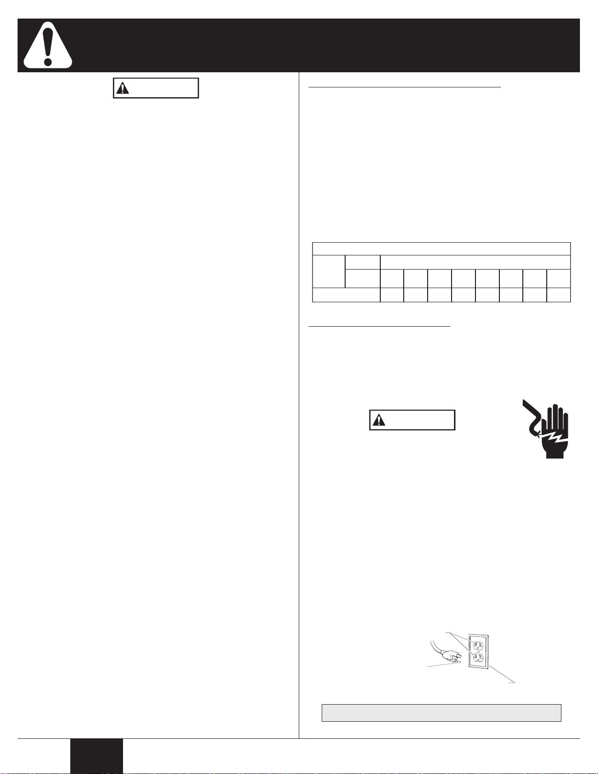
Minimum gauge for extension cords
Cord length (feet)Voltage
Ampere
rating
range
3 - 4
120V
25-50
100 150 200 250 300 400 500
18
16 14 12 12 10 10 8
operating the equipment. Save these instructions
Indicates a hazardous situation which, if not avoided, could
result in death or serious injury.
HAZARD: GENERAL
Can cause severe injury or property damage.
• Read all instructions and safety precautions for equipment and
spray material before operating any equipment.
• Comply with all appropriate local, state, and national codes
governing ventilation, fire prevention, and operation.
• This unit is intended for use with water-based textured
materials only
or oil-based materials.
•
Keep sprayer out of the reach of children.
• Hearing protection is recommended for extended use.
• Always wear appropriate gloves, eye protection and a
respirator or mask when painting.
• Do not operate or spray near children. Keep children away
from equipment at all times.
• Do not overreach or stand on an unstable support. Certain
material overspray can make floors slippery. Keep effective
footing and balance at all times. Wear rubber-soled shoes.
• Stay alert and watch what you are doing.
• Do not operate the unit when fatigued or under the influence of
drugs or alcohol.
• Use only manufacturer authorized parts. User assumes all
risks and liabilities when using parts that do not meet the
minimum specifications and safety devices of the turbine
manufacturer.
• Wear protective eyewear and ear protection.
• Wear long-sleeved work clothing to prevent skin irritation.
• DO NOT pull the trigger while the turbine is turned OFF (l) and
the hopper is filled with material. Material could leak down into
the turbine.
•
Always remove turbine before cleaning.
HAZARD: DUST INHALATION
Dust or mist created by this sprayer may cause eye, skin,
throat or respiratory irritation.
• Avoid inhalation of mist or dust. Wear a NIOSH / MSHA
approved respirator when using this equipment or for anyone
entering the work area.
•
Maintain proper ventilation to reduce mist / dust exposure.
• NO EATING, DRINKING OR SMOKING should be done in the
work area to prevent ingesting contaminated paint particles.
Workers should wash and clean up BEFORE eating, drinking,
and smoking. Articles of food, drink, or smoking should not be
left in the work area where dust would settle on them.
• Follow all warnings and recommendations provided by the
textured coating manufacturer.
. DO NOT use this sprayer with any flammable
Important Electrical Information
Use only a 3-wire extension cord that has a 3-blade grounding plug
and a 3-slot receptacle that will accept the plug on the product.
Make sure your extension cord is in good condition. When using
an extension cord, be sure to use one heavy enough to carry the
current your product will draw. An undersized cord will cause a
drop in line voltage resulting in loss of power and overheating. A14
gauge or 12 gauge cord is recommended. If an extension cord is
to be used outdoors, it must be marked with the suffix W-Aafter the
cord type designation. For example, a designation of SJTW-A
would indicate that the cord would be appropriate for outdoor use.
Wagner Spray Tech accessory extension cords recommended:
P/N 0090241 20 foot extension cord.
P/N 0090242 35 foot extension cord.
Grounding Instructions
This product must be grounded. In the event of an electrical short
circuit, grounding reduces the risk of electric shock by providing an
escape wire for the electric current. This product is equipped with a
cord having a grounding wire with an appropriate grounding plug.
The plug must be plugged into an outlet that is properly installed
and grounded in accordance with all local codes and ordinances.
DANGER--Improper installation of the grounding
plug can result in a risk of electric shock.
If repair or replacement of the cord or plug is necessary, do not
connect the green grounding wire to either flat blade terminal.
wire with insulation having a green outer surface with or without
yellow stripes is the grounding wire and must be connected to the
grounding pin.
Check with a qualified electrician or serviceman if the grounding
instructions are not completely understood, or if you are in doubt as
to whether the product is properly grounded. Do not modify the
plug provided. If the plug will not fit the outlet, have the proper
outlet installed by a qualified electrician.
This product is for use on a nominal 120 volt circuit and has a
grounding plug that looks like the plug illustrated below. Make sure
that the product is connected to an outlet having the same
configuration as the plug.
The
HAZARD: ELECTRIC SHOCK HAZARD
May cause severe injury.
• Always remove turbine before cleaning.
• Power cord must be connected to a grounded circuit.
• Never submerge electrical parts.
• Never expose the equipment to rain. Store indoors.
English
This product is intended for household use only.
2
Page 3
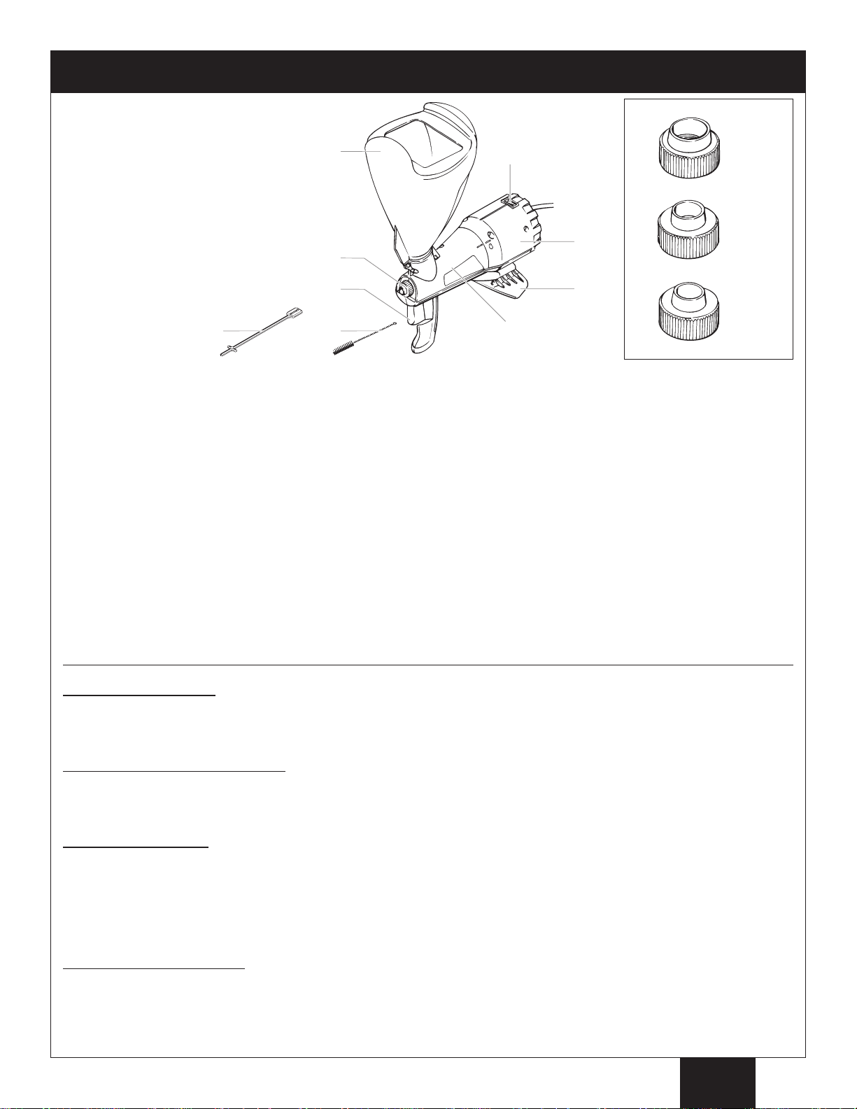
(a)
(b)
(c)
(d)
(e)
(f)
(g)
(h)
(i)
a) ON / OFF switch
1)
2)
3)
white
(large)
yellow
(medium)
black
(small)
b) Turbine
c) Arm rest / Stand
d) Sprayer body
e) Hopper
f) Spray nozzle
1) large nozzle
2) medium nozzle
3) small nozzle
g) Trigger
h) Cleaning brush
i) Nozzle holder
Components and Description
ON/OFF Switch. . . . . . . . . . . The ON/OFF switch turns the power to the sprayer on and of
Turbine . . . . . . . . . . . . . . . . . The turbine provides air flow that delivers the material from the sprayer.
Lock N Go™ . . . . . . . . . . . . This sprayer has been designed with Lock N Go™
Trigger. . . . . . . . . . . . . . . . . . The trigger controls the delivery of the fluid being pumped. The farther the trigger is pulled, the
more material will flow from the nozzle. DO NOT pull the trigger while the turbine is turned OFF (l)
and if there is material in the hopper. This may cause material to flow into the turbine.
Spray nozzle. . . . . . . . . . . . . This unit is equipped with three dif
(large, medium, small) that determine the volume of material being sprayed. The bigger the
opening, the more material will flow from the nozzle.
Hopper . . . . . . . . . . . . . . . . . The hopper can rotate 180º to accomodate a higher spraying angle.
be placed on the rear of the hopper for increased stability during usage.
Arm rest . . . . . . . . . . . . . . . . The sprayer has been designed to rest comfortably on the user ’s arm during usage.
Nozzle holder . . . . . . . . . . . . The nozzle holder can be threaded through the nozzles and then wrapped around the power cord
for easy stoage.
ferent spray nozzles. The nozzles have different opening sizes
technology, allowing for easy cleanup.
f (O=OFF, l=ON).
The user’s free hand may also
Product Description:
The Power Tex®is intended for use for the residential application of water-based textured materials to ceilings, walls, or other
surfaces. The Power Tex®is an ideal tool for applying textured material to small areas or for repairing damaged sections of
knockdown or acoustic texture surfaces.
Materials that can be sprayed:
This unit has been designed to be used with 1) aggregated materials such as simulated acoustic (“popcorn”) and 2) unaggregated
materials such as diluted joint compound for knockdown and orange peel. Make sure to follow all the manufacturer’s
recommendations and warnings when mixing and using textured materials.
Mixing the material:
When mixing the material you are going to spray, follow the manufacturer’s directions. It is very important that the material
you use is properly mixed. The material should appear creamy, wet, and lump-free, similiar to pancake batter (refer to chart on
page 5 for variations). DO NOT mix the material inside the hopper. Use a separate container to mix the material. For best
results, use an electric drill with a paint-mixer attachment when mixing the material. Make sure the material settles for 15 minutes
before using and then mix again thoroughly
separate batches for one job may give inconsistent results.
. To ensure proper consistency, mix enough material to complete the job. Mixing
Preparing the work area:
Texture spraying creates a great deal of dust and overspray material. It is necessary that you cover with drop cloths anything you
do not want sprayed (walls, windows, floors, furniture) and remove as many non-essential items from the room as possible. Make
sure the work surface has also been properly prepared. Application over unsealed, stained, improperly prepared, or not
completely dry surfaces may cause discoloration and adhesion problems.
3
English
Page 4
Ceilings
Walls
Setup
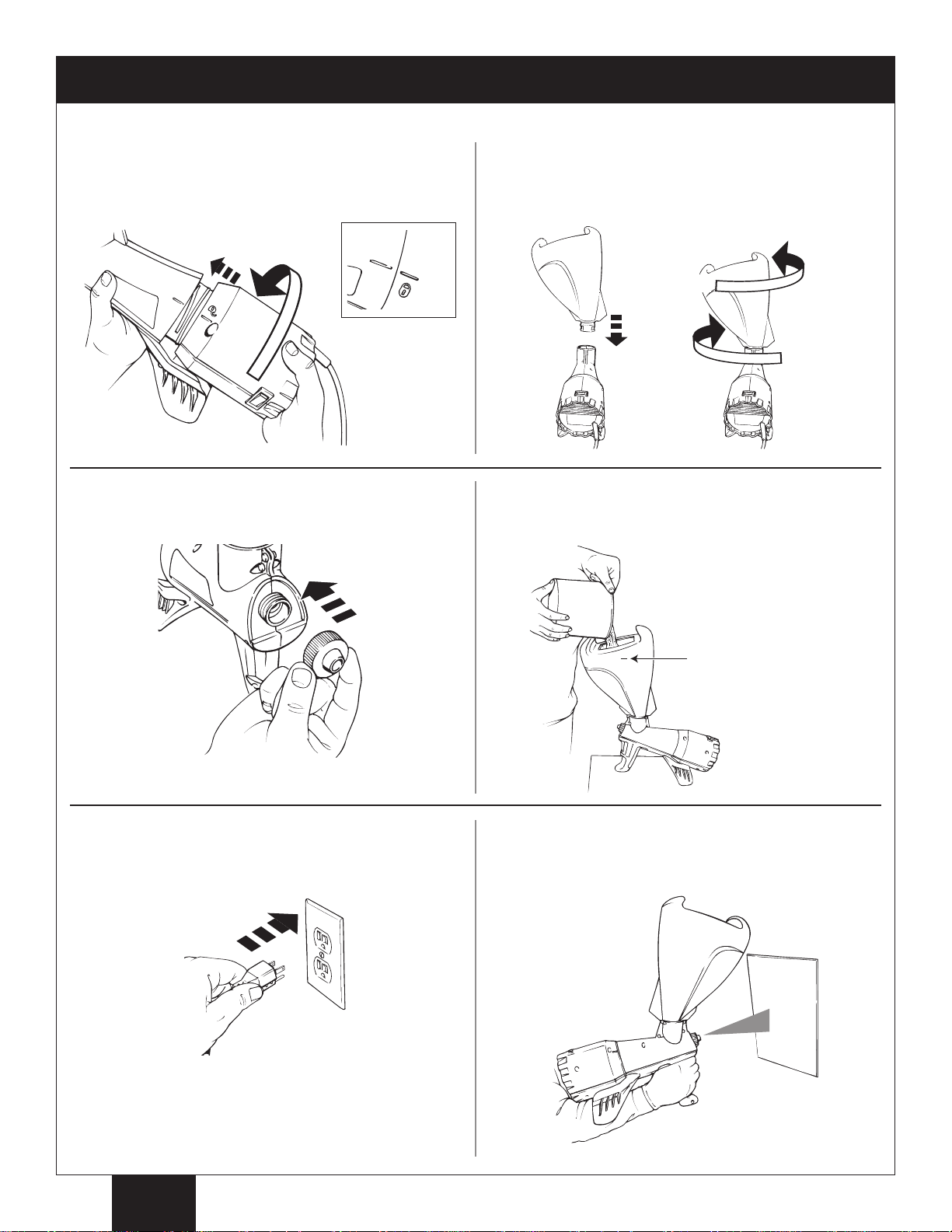
1. Line up the “unlock” symbol on the turbine with the guide
on the sprayer. Twist the two halves in opposite
directions until the “lock” symbol on the turbine lines up
with the guide on the sprayer.
3. Attach desired nozzle by threading it onto the end of the
sprayer.
2. While facing the rear of the sprayer/ turbine assembly,
insert the hopper into the receptacle with the hopper
oriented as shown. Depending on what surface you plan
to spray, turn the hopper 1/4 turn in either direction to lock
it in place.
4. Slowly fill the hopper with the material you plan to use.
Be sure the sprayer/ turbine assembly is resting on a flat,
stable surface that is covered by a drop cloth.
5. Plug the power cord into an extension cord. Plug the
extension cord into a grounded outlet. Turn the switch to
ON (l).
The turbine will start up and air will blow from the nozzle.
No material will flow from the nozzle until the trigger is
pulled.
Do not exceed fill
point as shown.
6. Place the arm rest over your forearm. Aim the sprayer at
a scrap piece of wood or cardboard to test the spray
pattern.
English
4
Page 5
Texture Spraying
45º65º
Do not exce
ed
2 fee
t
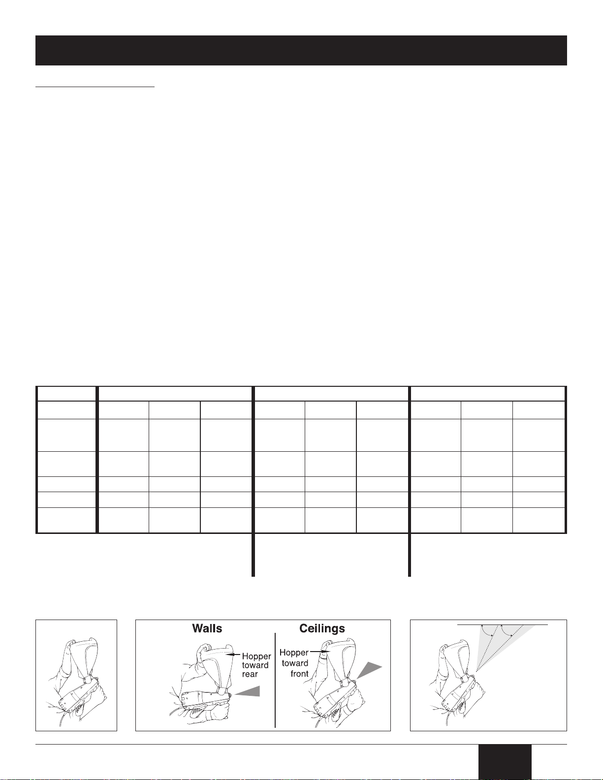
Texture Simulated Acoustic (popcorn) Knockdown Orange Peel
Effect Fine CoarseMedium Fine CoarseMedium Fine CoarseMedium
Trigger pull
Full FullFull Full FullFull Half FullFull
Paint needed
after application
No NoNoYes YesYes Yes YesYes
Material
Thickness
Slightly thinner
(add water)
Slightly thicker
(add material)
Pancake
batter
Slightly thinner
(add water)
Slightly thicker
(add material)
Pancake
batter
Slightly thinner
(add water)
Pancake
batter
Slightly thinner
(add water)
Fine
aggregated
Coarse
aggregated
Medium
aggregated
Unaggregated
or thinned
joint compound
Unaggregated
or thinned
joint compound
Unaggregated
or thinned
joint compound
Unaggregated
or thinned
joint compound
Unaggregated
or thinned
joint compound
Unaggregated
or thinned
joint compound
Material to
purchase
Nozzle color
Yellow YellowYellow Black WhiteYellow Black YellowBlack
*When using knockdown, let material dry for
10-15 minutes after application. Use a soft
squeegee to “knock down” the material. Do not
wait more than 30 minutes after application to
knock down the material.
General Spraying Tips:
• The sprayer can feel heavy when full of spraying material. It is recommended that your free hand be placed at the rear of the
hopper for increased support during usage (see figure 1).
• Swivel hopper forward when spraying a ceiling; swivel hopper toward the rear when spraying a wall (see figure 2).
When spraying, try to keep the nozzle no farther than 2 feet away. When doing ceilings keep the sprayer between a 45º-65º
•
angle to the spraying surface (see figure 3). Y
achieve desired results.
• If spraying a large surface, use broad, sweeping, side-to-side strokes with continuous trigger activation for optimal coverage. It is
recommended that the surface be sprayed in slightly overlapping, 3’ x 3’ sections. Spray each section in one direction, then spray
at a perpendicular angle to complete the section.
• The thickness of the spray material can be adjusted by adding small amounts of water or material.
• Texture spraying creates a great deal of dust and overspray material. It is recommended that you adequately cover anything you
do not want sprayed with drop cloths (walls, windows, floors, furniture) and remove as many non-essential items from the room as
possible.
• The spray pattern can be adjusted by switching to a different nozzle. Before removing/changing nozzles, always turn the sprayer
OFF (O) and unplug the power cord.
When repairing a small area, it is a good idea to scrape away any damaged material that may be around the affected area. Spray
•
an area slightly larger than the affected area to create a uniform look. Generally, when repairing a small area, the small nozzle
should be used, and the trigger should be activated using light, intermittent pressure.
• All new surfaces should be covered with primer prior to texture spraying.
• Knockdown and orange-peel materials may need to be painted after application to create a final uniform color.
ou can adjust the spraying angle, nozzle size, and vary trigger activation to
Refer to the chart below for assistance with all the variables involved in texture spraying. Texture spraying is not an exact
science, and the variables below may need to be adjusted to meet your particular texture spraying needs.
Figure 1 Figure 2
5
Figure 3
English
Page 6
Cleanup
(a)
(b)
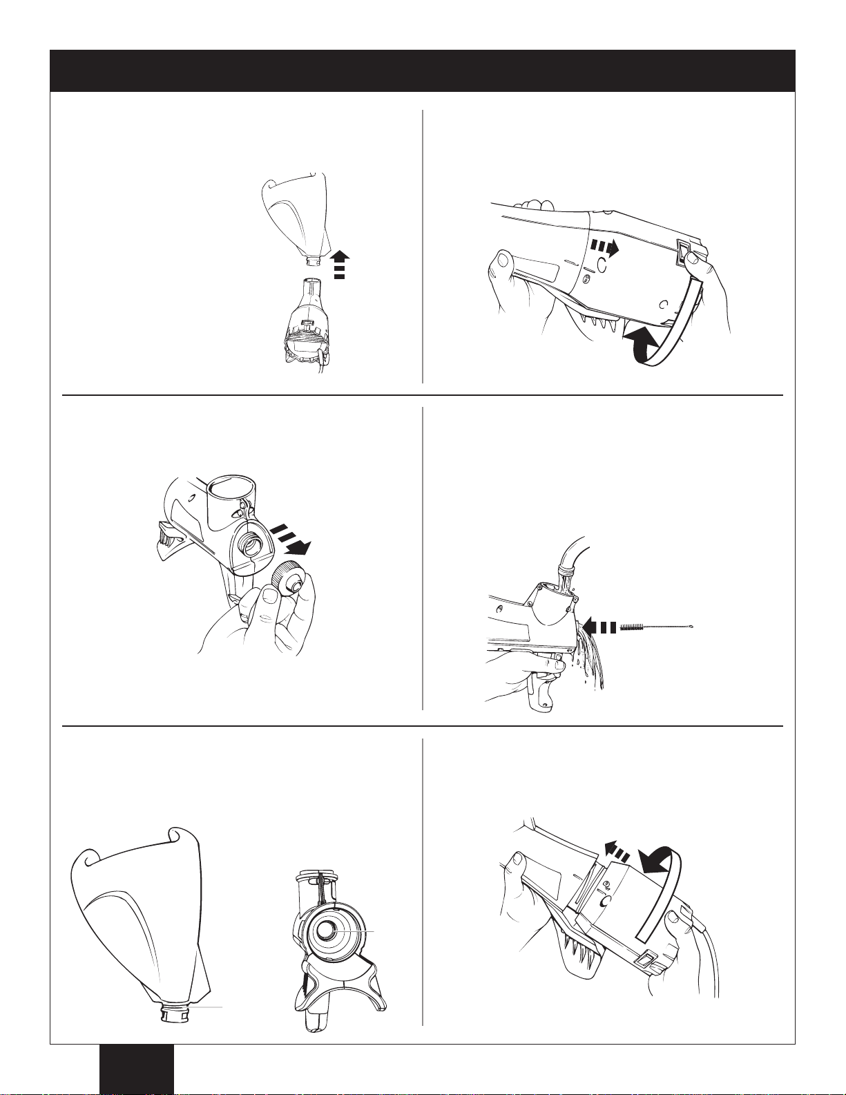
1. Turn the switch OFF (O) and unplug the power cord.
Make sure the hopper is empty of spraying material. Pour
any leftover material into a separate container. Remove
the hopper when empty.
NOT attempt to
DO
remove the hopper
from the sprayer if it
is full of material.
3. Remov e n o zz l e f ro m t he sp r ay e r. 4. The nozzle, sprayer and the hopper can now be hand-
2. Unlock turbine from sprayer by turning the two halves in
opposite directions. The “unlock” symbol on the turbine
should come toward the guide on the sprayer. Set
turbine aside in a dry area.
cleaned using warm, soapy water and the cleaning brush
provided with the unit. Let faucet water run into the area
where the hopper connects to the sprayer. While the water
is running, activate the trigger to fully clean the nozzle area
. DO NOT sumberge the turbine. The outside of the
turbine can be wiped clean with a damp cloth.
5. With the lubricant included with your sprayer, lubricate the
O-ring on the hopper (a) and lubricate the outer edge of
the plunger inside the rear of the sprayer housing (b).
Pull and release the trigger a few times to distribute the
lubricant.
Some water may flow
out the rear of the
sprayer body.
6. After all components are clean, wipe down with a dry
cloth. Reassemble the sprayer/turbine. ON/OFF switch
should be facing upward. Clean turbine labels with a
damp cloth.
English
6
Page 7

Troubleshooting / Warranty
Problem
A. The sprayer does not start.
B. No material coming from the
sprayer.
C. Application speed too slow.
D. Sputtering/intermittent flow.
E. Clumpy spray pattern.
F. Material leakage at hopper
connection.
Cause
1. The sprayer is not plugged in.
2. The ON/OFF switch is set to OFF.
3. No voltage at wall plug.
5. The extension cord is damaged or has too
low a capacity.
6. There is a problem with the turbine.
1. Material too thick.
2. Nozzle too small for thickness of material.
3. Plugged or dirty sprayer.
1. Nozzle too small.
2. Plugged or dirty sprayer.
3. O-ring on turbine damaged, missing or dirty.
1. Hopper empty.
2. Plugged or dirty sprayer.
1. Material not sufficiently mixed.
1. O-ring on hopper damaged, missing or dirty.
Solution
1. Plug the sprayer in.
2. Turn the ON/OFF switch to ON.
3. Properly test the power supply voltage.
5. Replace the extension cord.
6. Take sprayer to Authorized Service Center.
1. Thin the material by adding water.
2. Switch to a larger nozzle and/or thin the material.
3. Thoroughly clean the sprayer.
1. Switch to a larger nozzle.
2. Thoroughly clean the sprayer.
3. Clean or replace the O-ring.
1. Fill the hopper.
2. Thoroughly clean the sprayer.
1. Mix the material.
1. Clean or replace the O-ring.
WAGNER ONE-YEAR LIMITED WARRANTY - Keep on File
This product, manufactured by Wagner Spray Tech Corporation (Wagner) is warranted against defects in material and workmanship
for one year following date of purchase if operated in accordance with Wagner’s printed recommendations and instructions. This
warranty does not cover damage resulting from improper use, accidents, user’s negligence or normal wear. This warranty does not
cover any defects or damages caused by service or repair performed by anyone other than a Wagner Authorized Service Center.
ANY IMPLIED WARRANTY OF MERCHANTABlLITY OR FITNESS FOR A PARTICULAR PURPOSE IS LIMITED TO ONE YEAR
FOLLOWING DATE OF PURCHASE. THIS PRODUCT IS DESIGNED FOR HOME USAGE ONLY. IF USED FOR COMMERCIAL
OR RENTALPURPOSES, THIS WARRANTYAPPLIES ONLY FOR 30 DA YS FROM DATE OF PURCHASE. WAGNER SHALLNOT
IN ANY EVENT BE LIABLE FOR ANY INCIDENTAL OR CONSEQUENTIAL DAMAGES OF ANY KIND, WHETHER FOR BREACH
OF THIS WARRANTY OR ANY OTHER REASON. THIS WARRANTY DOES NOT APPLY TO ACCESSORIES.
If any product is defective in material and/or workmanship during the applicable warranty period, return it with proof of purchase,
transportation prepaid, to any Wagner Authorized Service Center. (Alisting of Service Center locations is enclosed with this product.)
Wagner’s Authorized Service Center will either repair or replace the product (at Wagner ’s option) and return it to you, postage
prepaid.
7
English
Page 8
Parts list • Liste de pièces • Lista de piezas
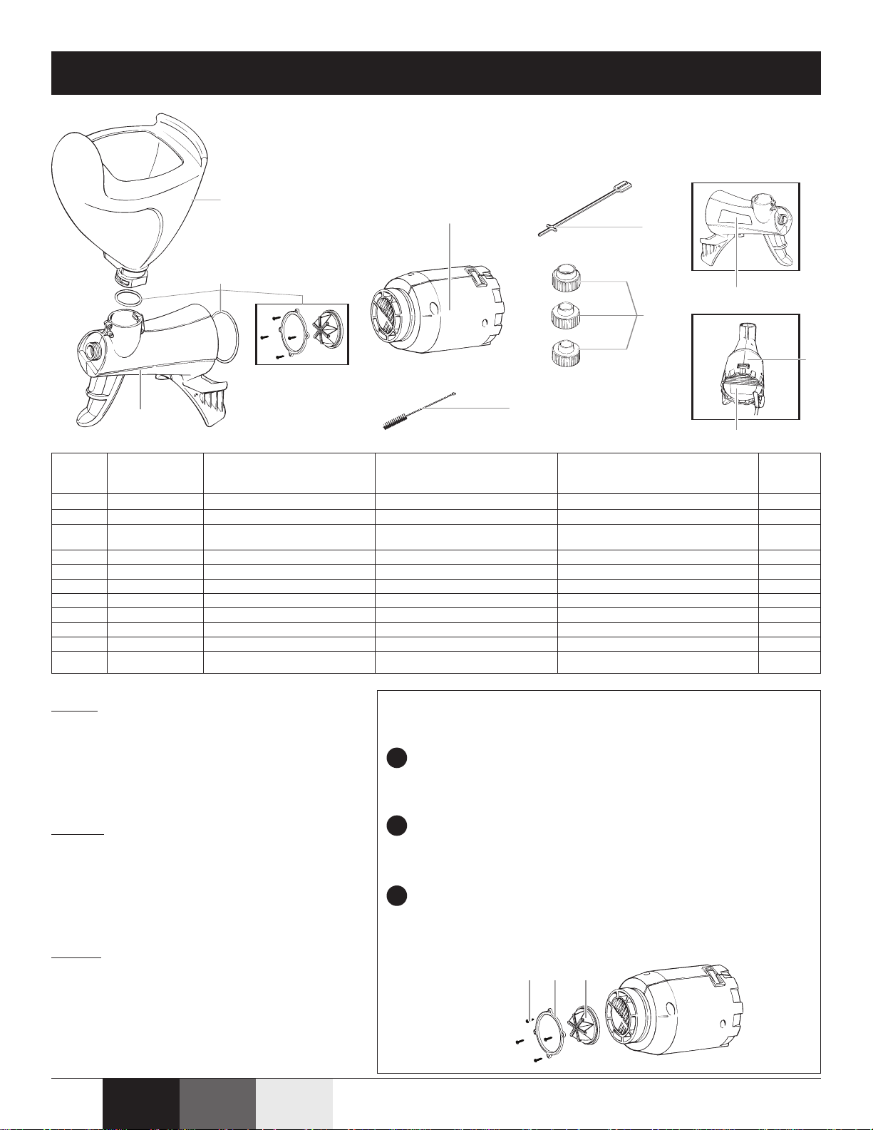
5
6
7
8
9
10
1
2
3
4
(a) (b) (c)
Parts List • Liste de pièces • Lista de piezas
Article
Articulo
English
*O-rings are located on the connecting areas of the
turbine and hopper.
***Includes all three nozzles (small, medium, and large)
All parts can be ordered by calling customer
service at 1-800-328-8251.
Français
*Les joints toriques sont situés sur les sections de
raccordement de la turbine et de la trémie.
***Inclut les trois buses (petite, moyenne et grosse).
Toutes les pièces peuvent être commandées en
appelant le service à la clientèle au 1 800 328-8251.
Espa
*Las juntas en forma de aro tórico se encuentran en
las áreas de conexión de la turbina y la tolva.
***Incluye las tres boquillas (pequeña, mediana y
grande)
Todas las partes se pueden ordenar llamando a la
línea del servicio al cliente: 1-800-328-8251.
Item
1) 0520103 Hopper Trémie Tolva 1
2) 0520104 Sprayer Pulvérisateur Rociador 1
3) 0520102 Turbine valve and Nécessaire de soupape de Juego de válvula de turbina y
4) 0520105 Turbine Turbine Turbina 1
5) 0514209 Cleaning brush Brosse de nettoyage Cepillo de limpieza 1
6) 0520101 Nozzle kit*** Nécessaire de buses*** Juego de boquillas*** 1
7) 0520324 Nozzle holder Support de buse Sujetador para boquillas 1
8) 0520801 Warning label Étiquette d’avertissement Etiqueta de advertencia 1
9) 0520802 Warning label Étiquette d’avertissement Etiqueta de advertencia 1
10) 0520805 Warning label Étiquette d’avertissement Etiqueta de advertencia 1
11) 9892550 Lubricant (not shown) Lubrifiants (non montré ) Lubricante (no demostrado ) 1
Part No.
N° de pièce
Pieza No.
English Description
o-ring kit* turbine et joints toriques* juntas de forma de aro tórico* 1
Français Description
Español Descripción
Quantity
Quantite
Cantidad
Replacing the turbine valve • Remplacement de la soupape de
turbine • Reemplácelo la válvula de la turbina
Remove the four valve ring screws (a) with a screwdriver.
1
Retirez le quatre vis d’anneau de soupape (a) avec un tournevis.
Quite los cuatro tornillos del anillo de la válvula (a) con un destornillador.
Remove the valve ring (b) and the old valve (c).
2
Retirez l'anneau de soupape (b) et la vieille soupape (c).
Quite el anillo de la válvula (b) y la vieja válvula (c).
ñol
Replace with new valve. Replace valve ring and screws.
3
Remplacez la nouvelle soupape. Remplacez l'anneau et les vis de
soupape.
Reemplácelo la válvula nueva. Reemplácelo el anillo de la válvula y
los tornillos.
FrançaisEnglish
Español
20
 Loading...