

Page 1

Item no. 2012
User’s Manual
5000 Watt AC Inverter
R
Page 2

5000 Watt AC Inverter by Wagan Tech
1
User’s Manual—Read before using this equipment
2
Thank you for purchasing this 5000 Watt DC to AC Power Inverter by Wagan Tech. With
minimal care and proper treatment it will provide years of reliable service. Carefully
read, understand and comply with all instructions before use. Keep this manual for future
reference.
ABOUT THIS INVERTER.
This power inverter converts 12 volts, direct current (12V DC) to 115 volts alternating
household current (115V AC). It easily powers TV/VCR combinations, microwave ovens,
refrigerators and small air conditioners. It also operates at high efficiency (up to 90%) that
results in longer running time and extended batter y life compared to other inverters with this
level of power output.
This inver ter has the highest surge capability in its class. Superior surge capability allows the
inverter to start most difficult motorized loads. Advanced microprocessor-controlled circuits
run cooler and are more reliable than competing units.
GENERAL INSTRUCTIONS:
• Keep the inverter away from any direct heat source or combustible materials.
• Keep well ventilated– this device generates heat.
• Keep the inverter away from combustible gases.
• Do not continuously operate any equipment over 5,000 watts.
• This inver ter is designed to operate from a 12 volt DC power source only.
• Do not attempt to connect the inverter to any other power source, including any AC
power source.
• Incorrect batter y polarity will damage the inverter and void the warranty.
• Keep this inverter in a dr y environment.
• Do not open the inverter; there are no user ser viceable par ts inside.
LOAD CONSIDERATIONS
When an appliance with a motor starts, it requires an momentary surge of power. This surge
of power is the “starting load” or “peak load”. Once started, the appliance requires less
power to continue to operate. This is known as the “continuous load”. It is important to know
the starting loads and the continuous loads of the appliances that are to be powered by the
inverter.
Appliance power is rated in watts. This information is usually stamped or printed on most
appliances and equipment. In some cases, a tool will be rated in amperes. To convert
from amps to watts, multiply: Amps x 115 (AC voltage) = Watts. This formula yields an
approximation of the continuous wattage load of that appliance.
The startup load of an appliance is a major factor of whether this inverter can power it.
Startup load is momentary. With many appliances, it is approximately twice the continuous
load but some appliance startup loads can be as high as eight times the continuous load.
To determine if an appliance or tool will operate with this inverter, run a test. This inver ter
will automatically shut down in the event of an output overload, so there is no danger of
damaging either the inverter or the equipment. When lit, t wo LED indicators signal a reason
why the inverter is shut down.
This inver ter may not properly operate some appliances with either speed control features
or dimmer controls. Some appliance GFCI power cords will not operate properly while
powered by this inverter. Again, the only way to be sure of proper operation is to try it.
SAFETY WARNING
THE INVERTER OUTPUT CAN BE LETHAL. IMPROPER USE OF THIS INVERTER MAY RESULT IN
PROPERTY DAMAGE, PERSONAL INJURY OR LOSS OF LIFE.
www.wagan.com
© 2010 Wagan Corporation
All Rights Reser ved
Wagan and wagan.com are trademarks used by Wagan Corporatio n
Page 3

BATTERY
AC OUTPUTS
VOLTS
OFF
ON
OVERLOAD
OVER TEMP
AMPS
MAX. 1500W
per outlet
1 32
5000 Watt AC Inverter by Wagan Tech
3
User’s Manual—Read before using this equipment
4
FRONT PANEL
The Front Panel view shows the inverter’s ON/OFF Switch, Indicators, direct wiring High
Current Terminals, four AC Outlets and optional Remote Switch Connector.
ON/OFF Switch
This switch controls operation of the inverter.
Over Temp LED
This indicator turns RED as the inverter shuts down because of excessive temperature.
Immediately turn off appliances if this occurs. Allow the inverter to cool before continuing.
Internal high-speed cooling fans automatically turn on when the inverter is switched on to
provide instant cooling. The inverter may overheat when it is being used in a location that
does not allow for adequate ventilation.
ON/OFF
Switch
Over Tem p
LED
Overl oad
LED
High Ou tput
Terminal s
Bar Gra ph
Displa ys
Four 115V
AC Outl ets
Remote
ON/OFF
Switch
Connec tion
Overload LED
This indicator turns RED as the inverter shuts down. Immediately turn of f some appliances
to reduce the load. If the continuous combined power requirement of appliances being
operated exceeds 5,000 watts, the inverter will overload. Sometime an appliance with very
high startup load will cause the inverter to shut down. If bat tery condition and cables should
suppor t the load, then a higher wattage inverter is required.
Bar Graph Displays
The inver ter is equipped with t wo bar graph displays to monitor DC input to the inverter.
These are used to help diagnose problems if they occur.
Volts Bar Graph:
This display is the measurement of the voltage at the DC terminals of the inverter, not
actual battery voltage. During high wattage applications the display may show a lower
voltage level than the battery because of voltage drop that occurs between the DC
input cables and the battery. This voltage drop should not be greater than 0.25 volts,
as a greater voltage will seriously reduce run time. This inverter will operate with input
voltage ranging from 10.5 to 15 volts of direct current (DC). If the inverter input voltage
level falls below 10.5 volts DC, an audible alarm will sound. When the voltage drops
below 10 volts DC, the inverter will automatically shut down.
During charging from a generator, solar panel or AC powered charger the battery
voltage will be higher than when it is resting. This inverter will automatically shutdown
if the input voltage is 15 volt s or higher. Voltages that are greater than 15 may cause
damage to the inverter. Damage caused by excessive voltage input is not covered
under warranty.
Amps Bar Graph:
This display indicates actual DC amperes of current being drawn from the battery
bank. Note that the A MPS display indicates a range of 120 to 600 amps. Current less
than 120 amps is not displayed. Note that for a 120 Amp reading the inver ter should
be powering 1,200 watt s of AC load.
High Output AC Terminals
There are three insulated terminals on the front panel of the inverter. These terminals are for
connecting 115 volt AC devices that require more than 15 amps to operate. Other uses are
for connection to distributed wiring that has multiple AC outlets. Any wiring that is directly
connected must be 10 gage or larger. Facing the front panel, the terminals are:
Left Middle Right
Ground Neutral Hot
www.wagan.com
© 2010 Wagan Corporation
All Rights Reser ved
Wagan and wagan.com are trademarks used by Wagan Corporatio n
Page 4

Sine Wave
5000 Watt AC Inverter by Wagan Tech
5
User’s Manual—Read before using this equipment
6
NEUTRAL and GROUND are bonded inside the inver ter to comply with the National Electric
Code (NEC) requirement that any AC source must have a neutral to ground conne ction.
Four 115V AC Outlets.
Each outlet will supply 15 amps, 115V AC maximum for powering appliances. Greater than
1,650 watts continuous power from an outlet may cause damage to the inverter and cause
possible injury.
Remote ON/OFF Switch Connection
An optional cable and switch assembly provides a convenient remote ON/OFF feature.
Contact your de aler for ordering information.
POWER INVERTER OUTPUT WAVEFORM
This inver ter’s AC output is a modified sine wave (MSW) 115 volts AC. The comparison of
modified sine wave and household AC is shown in the figure below.
This modified sine wave has a root mean square (RMS) voltage of 115 volts. Most ordinary
AC voltmeters are calibrated to read “average” voltage and assume that the AC waveform
will be a pure sine wave. These meters will not correctly read MSW voltage, and will display
about 20 to 30 volts too low. Any multi -meter identified as “TRUE RMS” will accurately read
MSW correctly.
INVERTER OUTPUT CHARACTERISTICS
The high output terminals and outlets of this inverter are wired in a similar manner to that of
house-hold wiring. The “ground” connection (the round conne ction on an outlet) is connected
to inverter frame’s ground. The two “blade” connections on an outlet are labeled HOT and
NEUTRAL because the neutral is connected to ground as in standard household distribution
wiring. This output conforms to the National Electric Code (NEC).
REAR PANEL
High-Speed Cooling Fan.
When the inverter is turned on, the fan automatically operates to cool the internal
temperature of the inverter.
High- Speed
Coolin g Fan
2 Nega tive (−) D C
Input Te rminals
2 Positive (+) DC Inpu t
Terminal s
Ground
Terminal
www.wagan.com
© 2010 Wagan Corporation
All Rights Reser ved
Wagan and wagan.com are trademarks used by Wagan Corporatio n
Page 5
5000 Watt AC Inverter by Wagan Tech
7
User’s Manual—Read before using this equipment
8
Two Negative DC (−) Input and Two Positive DC (+) Input Terminals
Both negative terminals are wired together inside the inverter. Similarly, both positive
terminals are wired together inside the inverter. For AC loads up to 2,500 watts only one
positive and one negative cable set is required. For AC loads from 2,500 to 5,000 watts use
two sets of cables.
After DC cables are installed, both sets of DC terminals should be insulated to protect from
accidental short circuits.
Ground Terminal.
This connection is located on the lower left of the re ar panel. It is for attaching a 6 gage
insulated safety ground wire. This safety wire is for protecting personnel if there is an
unlikely failure in either the cabling or enclosure insulation. Do not directly connect this
ground connection to the negative DC terminal. This safety wire is to be connected to the
vehicle frame or earth ground. This is described in the installation procedure.
PLANNING THE INVERTER SYSTEM
Any large wattage inver ter system requires planning before installation. There are several
steps to the planning process so the user must determine the following:
• Maximum inverter wattage required.
• Operating time (run time) neede d bet ween battery recharges.
• Battery bank capacity in amp-hours.
• Charger requirement to charge batteries within a practical time.
• Distance between batter y bank and inverter.
DETERMINING MAXIMUM APPLIANCE WATTAGE
Maximum AC appliance wat tage is the first factor in planning bat tery and charging systems.
Some background:
Large microwave oven specifications list cooking power (watts) and appliance power.
Appliance power is the AC load the inverter has to supply.
Most other electrical tools, appliances and audio/video equipment have labels that list the
unit’s power requirements in watts. If the tool or device is rated in amps, multiply the amps
by 115 (115V AC) to determine the watts. For example, a power tool rated at 4 amps will
draw 460 watts. Determine the wattage of each appliance you need to simultaneously
operate. Add all of the appliance wattages to obtain an estimated “total wat ts” number.
Remember to consider the startup surge that motorized appliances will cause. Do not exceed
the surge rating of this inverter (10,000 watts) this can cause imme diate overload shut down.
At 5,000 watts continuous output this inver ter requires a DC power supply (battery bank)
that can continuously supply 50 0 amps at 12V DC for the duration of the run time.
CONFIGURING THE BATTERY BANK
To determine the minimum bat tery ampere-hour rating that you will need to operate
appliances from the inverter and any DC appliances powered by the battery bank, follow
these steps:
1. List the maximum continuous wattage that the inverter has to supply.
2. Estimate the number of hours the appliances will be in use bet ween battery
recharges. This will vary depending on appliances. For example, a t ypical home use coffee maker draws 500 watts during its brew time of 5 minutes. It maintains
the temperature of the pot, requiring 100 watts. Typical use of a microwave oven
is only for a few minutes. Some longer operating time appliances are lamps, TVs,
computers and refrigerator/freezers.
3. Determine the total watt-hours of energy needed. This is done by multiplying
average power consumption in wat ts by hours of run time. For example: 1,500
watts for 10 hours = 15,000 watt hours. To get an estimate of the maximum current
(in amps) that a batter y bank must be capable of delivering to the inverter, divide
the load watts by ten. For example a 1,500 wat t appliance load will need 150
amps at 12 volts DC. Using the 1,500 watts (or 150 amps) for 10 hours example
as above, then 150 amps is needed for 10 hours. This provides us with the basic
amp- hours (AH) of battery that is required. Ten hours at 150 amps e quals 1,500
amp- hours (AH). This answer is just a beginning because there are additional
factors that determine actual run time. These include:
• AC appliance load and time in use (basic AH).
• Cable gage and length (cable losses).
• Charge level of the batteries (between use, chargers have to be able to
fully charge the batteries).
• Temperature of the batteries (colder batteries provide fewer amps).
• Age and condition of the batteries (older batteries lose AH capacity).
• Compliance with turning off unnecessary AC loads.
• Use of DC appliances and compliance with turning off unnecessary DC
loads.
DERATING THE BATTERY BANK
Most le ad- acid batteries have a rating expressed in amp-hours (AH). The most common
rating of AH is “at the 20 hour rate”.
NOTE: Despite several internet explanations, there is no relationship between cold cranking
amps (CCA) and amp ere- hours (AH).
www.wagan.com
© 2010 Wagan Corporation
All Rights Reser ved
Wagan and wagan.com are trademarks used by Wagan Corporatio n
Page 6
5000 Watt AC Inverter by Wagan Tech
9
User’s Manual—Read before using this equipment
10
For example; if a 20 AH battery is discharged at a 1 amp rate, is will take 20 hours to
discharge that battery. The terms “charged” and “discharged” relate to actual batt ery
voltage. This means that the output voltage of a nominal 12 volt battery starts at 13.2 volts
(fully charged) then drops to 10.6 volts (discharged). If the load on the battery causes
the batter y to discharge faster than the 20 hour rate, the capacit y (AH) of the battery is
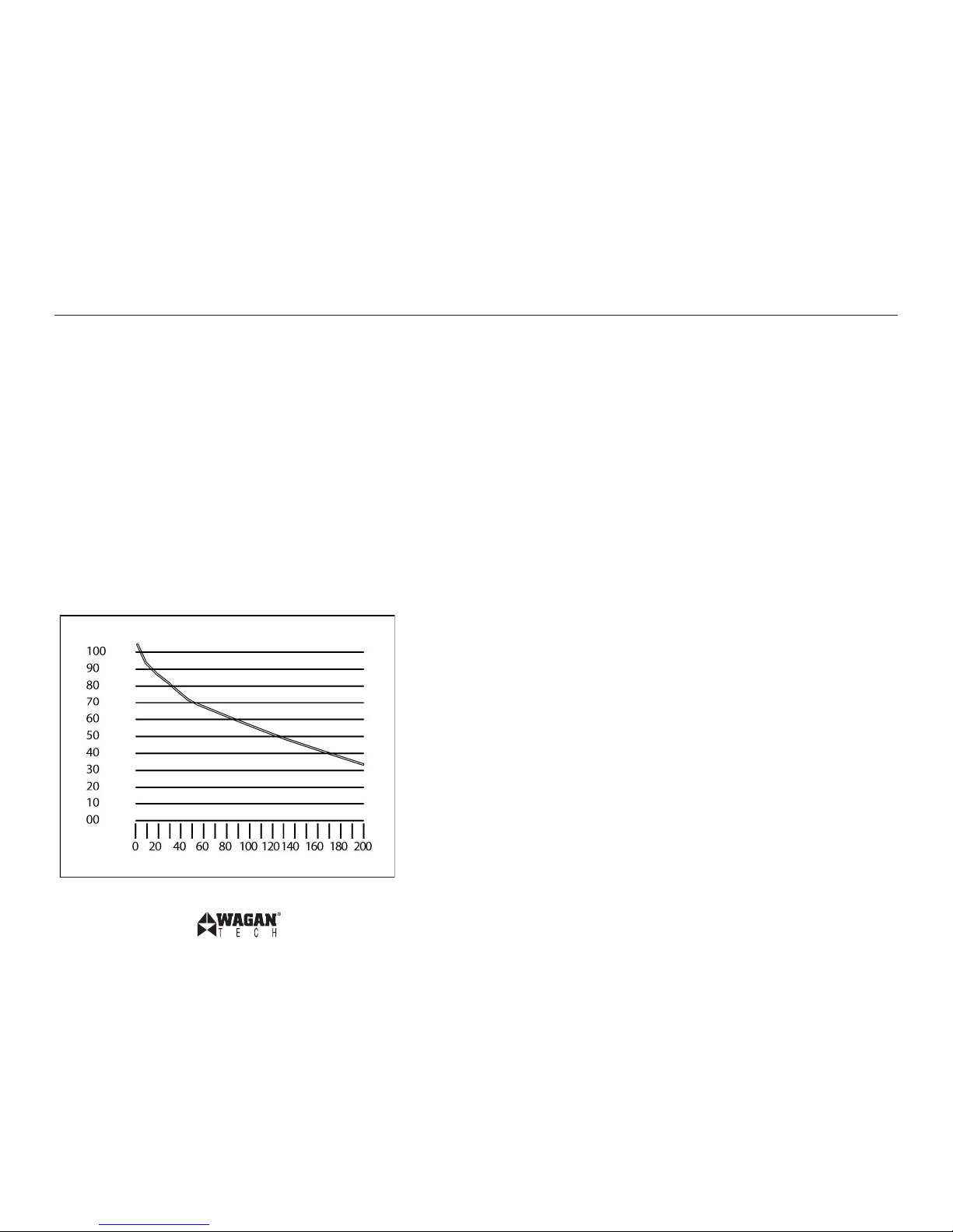
measurably reduced (derated). Derating is a major run time factor. The curve below can help
to determine what the battery bank can deliver under load. The results are used to estimate
how much additional bat tery capacity is needed to achieve the desired run time.
The lef t vertical numbers of the cur ve represents percentage of the batter y capacity at the 20
hour rate. In this example, the user needs a one hour run time. If the example battery is 220
AH (20 hour rate), and the load is 220 amps that is 100% (horizontal number) of the AH (20
hour rate), starting at the 100% horizontal point and looking up to the cur ve the results are
that only 56% of the battery capacit y is available. This means that a higher battery cap acity
is required to get the desired run time: one hour. The curve also shows that a load of 200%
of the 20 hour rate yields only 31% of the batter y capacity. The installer must carefully plan
the cap acity of bat tery bank or the run time may be seriously affected. To the inexperienced
installer, several trial bat tery capacities may be required to make sure a large enough
battery capacit y is available to achieve the desired run time.
The cur ve can be applied to any lead acid bat tery under load providing that it has an AH
rating at the 20 hour rate.
Continuing with the previous example, the 150 amp load will need to run for 10 hours, so
we begin configuration with a 1,500 AH battery. If the vertical is 1,500 and the horizontal
is 150 amps, the percentage of load on the batter y is 10%. The curve shows that the 1,500
AH is derated to 90% of maximum. This means that the battery will have to be 16,500 AH
for the full 10 hour run time. It is important to add some extra batter y capacity, because as
the batteries age they will lose AH capacit y.
CONFIGURATING THE BATTERY BANK
Six volt, 220 AH “golf cart” bat teries were selected for these illustrations because they are
generally readily available and relatively inexpensive. They are deep-cycle type and with
regular recharging they have a relatively long life. These batteries are “flooded” type; they
freely vent hydro gen and oxygen while under charging and heavy discharge. They must be
vented to outside air to prevent accumulation of explosive gases.
Fusing Requirements
NOTE: It is important that for this 5000 watt inverter has two ANL 400 ampere or
equivalent main b attery fuses be added to the positive (+) batter y cable as close as possible
to the battery bank’s positive terminal. The fuse amperage rating must be sized to allow
simultaneous op eration of all the AC appliances to be powered, allowing for the momentar y
high startup current requirements of inductive loads. Use the recommended fuse block (fuse
holder) and fuse, or an electrical equivalent. ANL type fuses and f use holders are readily
available from marine supply de alers.
The fuses are very important to protect equipment, batteries and personnel. The fuses protect
against b attery explosion if the cables that connect to the inver ter accidentally short.
www.wagan.com
© 2010 Wagan Corporation
All Rights Reser ved
Wagan and wagan.com are trademarks used by Wagan Corporatio n
Page 7
INVERTER
Safety Ground
6V
220AH
Fuse(s)
Fuse(s)
6V
220AH
6V
220AH
6V
220AH6V220AH
6V
220AH
+
–
+
–
+
–
+
–
+
–
+
–
5000 Watt AC Inverter by Wagan Tech
11
User’s Manual—Read before using this equipment
12
READ AND COMPLY WITH THE WARNING BELOW
EXPLODING BATTERIES CAN SPRAY MOLTEN LEAD, HOT SULFURIC ACID AND OTHER METAL
AND PLASTIC FRAGMENTS. BATTERIES THAT ARE CHARGING OR UNDER HIGH DISCHARGE
RATES PRODUCE EXPLOSIVE HYDROGEN GAS INTO THE SURROUNDING AREA. BE SAFE–
FUSE THE BATTERY BANK AND MAKE SURE THE BATTERIES ARE PROPERLY VENTILATED.
DC Cable Gage
Minimize cable losses by using the thickest wire available, and the shortest practical length.
If the inverter and the battery are positioned within four feet of each other, a minimum of
0 gage (zero gage) insulated copper wire should be used to make the connections. If the
distance is longer than 4 feet, heavier wire will be required. If insulated aluminum wire is
used instead of copper wire, 00 gage is a substitute for 0 gage copper wire.
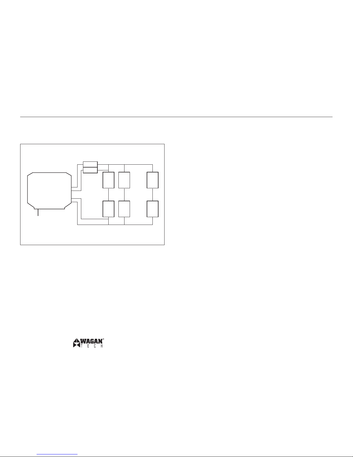
Battery Bank Diagram
The diagram below shows inverter connections to a battery bank with recommended fuse
protection.
CONNECTING THE INVERTER
General information
Loose connections will result in a severe voltage drop that can cause damage to connectors,
conductors and insulation and can cause sparking. Reverse polarity connection will blow
the fuses in the inverter and can permanently damage to the inverter. Damage caused by
reverse polarit y will void the warranty.
There are two sets of DC input terminals to ease cable connections and reduce the need for
larger gage cables. For AC loads less than 2,500 watts only one set of cables is required.
For loads over 2,500 watts use two sets.
Procedure
1. Make sure the cables are the proper gage and have the fuse holders as close to the
battery bank’s positive (+) terminal.
2. Install the fuses in the positive (+) cables.
3. Make sure the ON/OFF switch located on the front panel of the inverter is in the
OFF (0) position. Disconnect any remote switch from the connector on the front
panel.
4. Locate the ground lug terminal at the rear of the inverter. Connect an insulated 6
gage copper wire to the terminal. The other end of the ground wire is connected to
a “proper” grounding point. Use the shortest practical length of wire. Connect this
wire to the chassis of your vehicle or to the grounding system in your boat. In a city,
the ground wire can connect to a metal cold water pipe that goes underground. In
remote locations, the ground wire can be connected to an “earth ground”. This can
be an at tachment to a 6 foot long copper clad metal rod driven into the ground. In
the unlikely event of a short circuit, operating the inverter without proper grounding
can result in electrical shock. Do not directly connect this ground wire to the
negative (−) DC Terminal.
5. NOTE: Crimp -on ring terminals are required on all cable ends. The cable ends
need to be stripped of insulation for approximately 5/16th of an inch before
crimping ring terminals. Select ring terminal size to fit the gage cable and inverter
and bat tery terminal diameters. Af ter crimping make sure that the cable connectors
are secure on the cables so there are no loose connections.
6. Use a medium blade common screwdriver and loosen the cable connector screw.
Insert the negative (−) cable end into the terminal. Tighten the screw to clamp the
cable end. Make sure you have a good, secure connection.
7. Recheck and make sure the DC cable fuses are installed in the fuse holders.
CAUTION: Making an initial connection bet ween the positive cable and the
inverter’s positive terminal may cause a spark. This is a normal and is a result of
capacitors in the inverter starting to charge. Because of the possibilit y of sparking,
it is extremely important that both the inverter and the battery bank be positioned
away from any source of flammable fumes or gases. Failure to heed this warning
www.wagan.com
© 2010 Wagan Corporation
All Rights Reser ved
Wagan and wagan.com are trademarks used by Wagan Corporatio n
Page 8
5000 Watt AC Inverter by Wagan Tech
13
User’s Manual—Read before using this equipment
14
can result in fire or explosion. Do not make the positive terminal connection
immediately after the batteries have been charging. Allow time for the battery
gasses to vent to outside air.
8. Attach the positive cable end to the positive (+) DC conne ctor on the inverter. Make
sure the connection is tight and secure.
9. Replace the connector covers and secure with the small retaining screws.
10. Turn ON (1) the inverter. The display on the front panel should show 10.5 to 15
volts depending on the voltage of the power source. When the voltage reading
does not fall within this range, check the connections of the wires to the terminals
on the p ower source and the inver ter to make sure they are secure. Also che ck the
voltage of the power source. Make certain that the high temperature or overload
LED indicators are not lit.
11. Turn OFF (0) the inver ter. The overload and over temperature LEDs may briefly
“flash”. This is normal. The audible alarm may also sound a short “chirp”. This is
also normal.
12. When you have confirmed that the appliance to be operated is turned off, plug the
appliance into one of the four AC outlets on the front panel of the inverter.
13. Turn the inverter on.
14. Turn the appliance on.
Note: If an extension cord is used from the inverter to the appliance, limit the extension cord
length to 50 feet or less. Make sure that the cord is properly rated to carry the appliance
load.
CHARGING THE BATTERY BANK
It is not the purpose of this inverter user’s guide to provide detailed information regarding
battery charging systems. However, the user should try to augment any charging system with
either wind power or solar power. These can continue to operate during power outages and
they also reduce recharge time. If automatic AC powered battery chargers do not provide
enough charging current for a larger batter y bank, is permissible to have t wo automatic
battery chargers connected to the bat tery bank.
REGULAR LOSS OF COMMERCIAL POWER
If the inverter system is used during commercial power outages that occur daily, configure
the charger system to replace energy during the time that commercial power is available.
Replacement of battery energy always requires more than was taken from the battery
(typically 130%). In the example used earlier in this document, the AC load ran for 10 hours.
If commercial power is available, there are approximately 14 hours left in the day to do the
recharging. The following is an example of what is necessary to recharge a battery bank
that has 16,500 AH of capacit y (as in the example above) and has been discharged to 10.5
volts (discharge d). The charger has to replace 2145 AH (1650 x 1.3 AH) in 14 hours. So the
charger must charge at a rate of 153 amps for 14 hours. As this charge current is distributed
among the bat teries in the battery bank, the current received by an individual battery is
within its charge rating. Be sure that the b attery is well vented as the area will likely have
accumulations of an explosive mixture of hydrogen and oxygen. Follow all recommendations
for use that are contained in the battery charger manual.
WARNING
THERE IS DANGER OF EXPLOSION. DO NOT CONNECT OR DISCONNECT CHARGER CABLES
DIRECTLY AFTER BATTERY DISCHARGE OR RECHARGE–MAKE SURE THAT THE BATTERY BANK
AREA IS WELL VENTED BEFORE ATTACHING OR REMOVING CABLES.
If the flooded lead acid bat teries are used, as examples given in this document, be sure t hat
periodic checks of batter y electroly te levels are accomplished. Follow battery manufacturer’s
instructions in keeping the electroly tes at the proper level. Be sure to use pure distilled water
when replacing evaporated electrolyte liquid.
ABOARD A VESSEL OR VEHICLE.
Manufacturer supplied engine driven alternators can usually be replaced with ones that can
continuously deliver higher amperage. This should be done at the outset. Keep the batteries
charging when the vessel or vehicle engine is operating. In the case of a vessel, make sure
that shore power is used to recharge the batteries whenever possible.
OPERATING ISSUES
Television and Audio Equipment Suggestions.
Although all inverters are shielded and filtered to minimize signal interference, some
interf erence with your television picture may be unavoidable, especially with weak signals.
However, here are some suggestions that may improve reception.
• First, make sure that the television antenna produces a clear signal under normal
operating conditions (i.e. at home plugged into a standard 110/120V AC wall
outlet). Also, ensure that the antenna cable is properly shielded and of good
qualit y.
• Change the positions of the inverter, antenna cables and television power cord.
• Isolat e the television, its power cord and antenna cables from the 12 volt power
source by running an extension cord from the inverter to the television set.
• Coil the television power cord or install a clamp -on ferrite choke (available from
electronic parts suppliers).
Note: Some inexpensive audio systems may have a slight “buzzing” sound when operated
with the inverter. This is caused by insufficient filtering in the audio system. The only solution
to this problem is to get a sound system with a higher quality power supply.
www.wagan.com
© 2010 Wagan Corporation
All Rights Reser ved
Wagan and wagan.com are trademarks used by Wagan Corporatio n
Page 9
5000 Watt AC Inverter by Wagan Tech
15
User’s Manual—Read before using this equipment
16
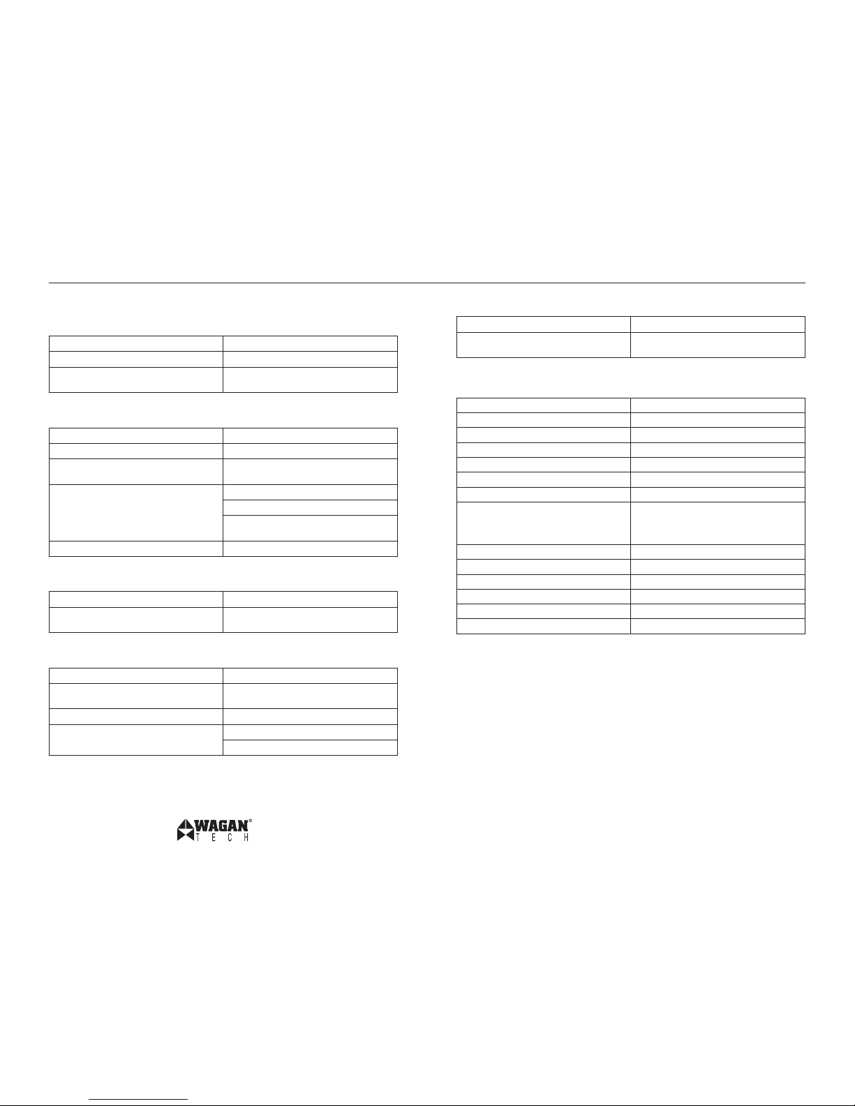
TROUBLESHOOTING
PROBLEM: Low or no output voltage
Reason Solution
Poor contact with battery terminals Clean terminals thoroughly
Using incorrect type of voltmeter to test
output voltage
Use true RMS reading meter
PROBLEM: Red bar graph
Reason Solution
Battery voltage below 10 volts Recharge or replace batter y
Equipment being operated draws too much
power
Use a higher capacity inverter or do not use
this equipment
Inverter is too hot (thermal shut down mode) Allow inverter to cool
Check for adequate ventilation.
Reduce the load on the inverter to rated
continuous power output
Unit may be defective See warranty and call customer service
PROBLEM: TV interference
Reason Solution
Electrical interference from the inverter Add a ferrite data line filter on to the TV
power cord
PROBLEM: Low batter y alarm on all the time
Reason Solution
Input voltage below 10.5 volts Keep input voltage above 10.5 volts to
maintain regulation
Poor or weak bat tery condition Recharge or replace batter y
Inadequate power being delivered to the
inverter or excessive voltage drop
Use lower gauge wire
Keep wire length as shor t as possible
PROBLEM: TV does not work
Reason Solution
TV does not turn on Contact TV manufacture to see if the TV is
compatible with a modified sine wave
SPECIFICATIONS
Name Description
Input 12V (10–15V) DC
Output 115V AC
Output wavefo rm Modifie d Sine Wave form
Continuous power 5,000 wat ts
Surge power 10,000 watt s
Efficie ncy Approximately 90 %
No load
Switch ON
Switch OFF
<0.3A DC
<0.2A DC
Battery low alarm 10.5 ± 0.5V D C
Battery low shutdown 10 ± 0.5V DC
AC outpu t socke ts 4 US standard gro unded
Power swit ch DC input ON/OFF control
Dimensio ns 20 x 9 x 7 in (50.8 x 22.9 x 7.8 cm)
Net Weight 22 lbs (9.98 kg)
NOTE
All spe cifications are t ypical at nominal line, half load, and 77ºF (25ºC) unless otherwise
noted. Specifications are subject to change without notice.
DISPOSAL OF INVERTER
Electronic products are known to contain materials that are toxic if improperly disposed.
Contact local authorities for disposal and recycling information.
www.wagan.com
© 2010 Wagan Corporation
All Rights Reser ved
Wagan and wagan.com are trademarks used by Wagan Corporatio n
Page 10
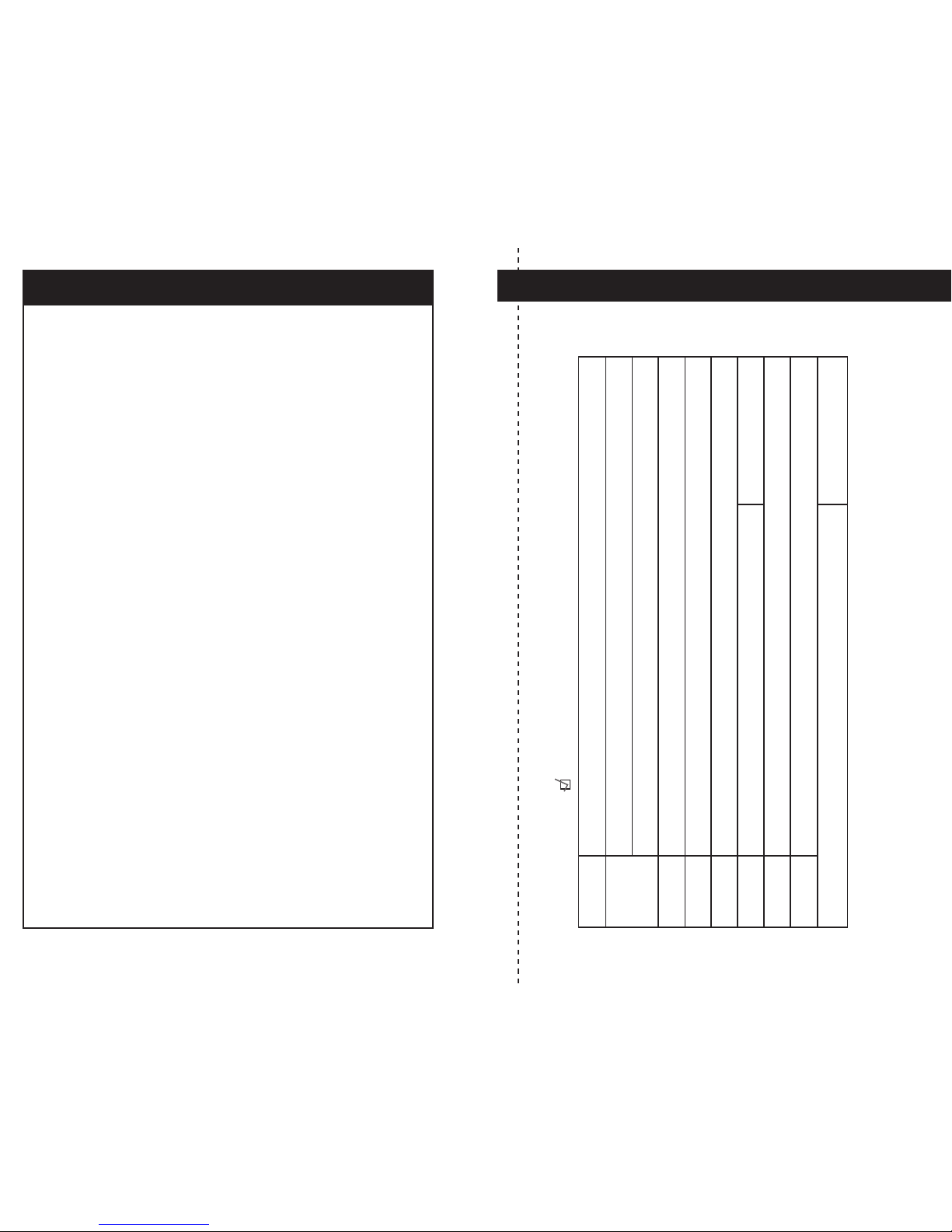
Please activate my limited warranty for WAGAN Corp.
WAGAN Corp. Limited Warranty Registration Form
Date
Item no.
Name
Mailing
address
City
State, Zip code
E-mail address
Item purchased
Store name
Date of purchase
Signature
All WAGAN Cor poration Products must be regis tered
within (30 ) days o f purchase to activate this warranty.
Mail the compl ete registratio n form, a long with a copy
of the o riginal s ales re ceipt to:
Attn: Customer Service
WAGAN Corporation
31088 San Clemente St.
Hayward, CA 94544
Detach and return right portion to the address above.
All WAGAN Corporation products are warranted to the original purchaser of this product.
Warranty Duration: This product is warranted to the original purchaser for a period of one
(1) Year from the original purchase date, to be free of defects in material and workmanship.
WAGAN Corporation disclaims any liability for consequential damages. In no event will
WAGAN Corporation be responsible for any amount of damages beyond the amount
paid for the product at retail. In the event of a defective item, please contact WAGAN
Corporation at (800) 231-5806 to obtain a Returned Merchandise Authorization number
(RMA#), and return instructions. Each item returned will require a separate RMA#. After
you have received the RMA# and the return instructions from WAGAN Corporation, please
follow the instructions and send the item with PREPAID SHI PPING, along with all of the
required documentation, a complete explanation of the problem, your name, address and
daytime phone number. WAGAN Corporation will, at its option, replace or repair the
defective part.
A Returned Merchandise Authorization number (RMA#) is REQUIRED when sending in any
defective item. WAGAN Corporation is not responsible for any it em(s) returned without
an official Returned Merchandise Authorization number. The item(s) must be returned with
prepaid shipping. WAGAN Corporation is not responsible for any shipping charges incurred
in returning the item(s) back to the company for repair or replacement. This warrant y is
void if the product has been damaged by accident, in shipment, unreasonable use, misuse,
neglect, improper ser vice, commercial use, repairs by unauthorized personnel or other
causes not arising out of defects in materials or workmanship. This warrant y is ef fective only
if the product is purchased and operated in the USA and does not extend to any units which
have been used in violation of written instructions f urnished.
Warranty Disclaimers: This warranty is in lieu of all warranties expressed or implied and
no representative or person is authorized to assume any other liability in connection with
the sale of our products. There shall b e no claims for defects or failure of performance or
product failure under any theory of tort, contract or commercial law including, but not limited
to negligence, gross negligence, strict liability, breach of warrant y and breach of contract.
Warranty Performance: During the above one (1) Year warranty period, a product with a
defect will be replaced with a comparable model when the product is returned to WAGAN
Corporation with an original store receipt. The replacement product will be in warranty for
the balance of the one (1) Year warranty period. Updated August 2008
WAGAN Corp. Limited Warranty
Page 11
www.wagan.com
U.S.A. & CAN Toll Free: 1.800.231.5806
1.510.471.9221
31088 San Clemente Street
Hayward, CA. 94544
U.S.A.
© 2008-2010 Wagan Corporation.
All Rights Reserved.
Wagan and wagan.com are trademarks used by Wagan Corporation.
Revised May 2010
 Loading...