

1
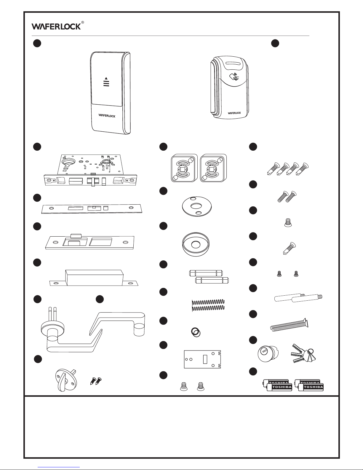
Front Reader
2
Inside control unit
9
Thumb turn set with 2 screws
L342 Parts List
www.waferlock.com
3
Electronic mortise
18
Fix Screws for Lip Plate
& Mortise Lock
24
Screw (with stick screw)
7
Outside Lever
8
inside Lever
5
Lip Plate
6
Dust-prove box
25
ANSI cylinder with keys
13
Spindle
23
Stick screw
16
Plate
10
Spring cage
26
Batteries (AAA)
22
Front reader slide cover screw
14
Lever spring
15
Outer lever ring
11
Mounting plate
12
Inside rose
version.01
4
Side plate
17
Side plate screw
20
Mounting Screw (for control unit)
21
Mounting Screw (for plate)
19
Lever screw
Federal Communication Commission Interference Statement
This equipment has been tested and found to comply with the limits for a Class B digital device, pursuant to Part 15 of the FCC Rules. These limits are designed to provide reasonable
protection against harmful interference in a residential installation.
This equipment gen erates, uses and can radiate radio frequency energy and, if not installed and used in accordance with the instructions, may cause harmful interference to radio
communications. However, there is no guarantee that interference will not occur in a particular installation. If this equipment does cause harmful interference to radio or television
reception, which can be determined by turning the equipment off and on, the user is encouraged to try to correct the interference by one of the following measures:
. Reorient or relocate the receiving antenna.
. Increase the separation between the equipment and receiver.
. Connect the equipment into an outlet on a circuit different from that to which the receiver is connected.
. Consult the dealer or an experienced radio/TV technician for help.
FCC Caution: To assure continued compliance, any changes or modifications not expressly approved by the party responsible for compliance could void the user's authority to operate
this equipment. (Example - use only shielded interface cables when connecting to computer or peripheral devices).
This device complies with Part 15 of the FCC Rules. Operation is subject to the following two conditions:
(1) This device may not cause harmful interference, and (2) This device must accept any interference received, including interference that may cause undesired operation.
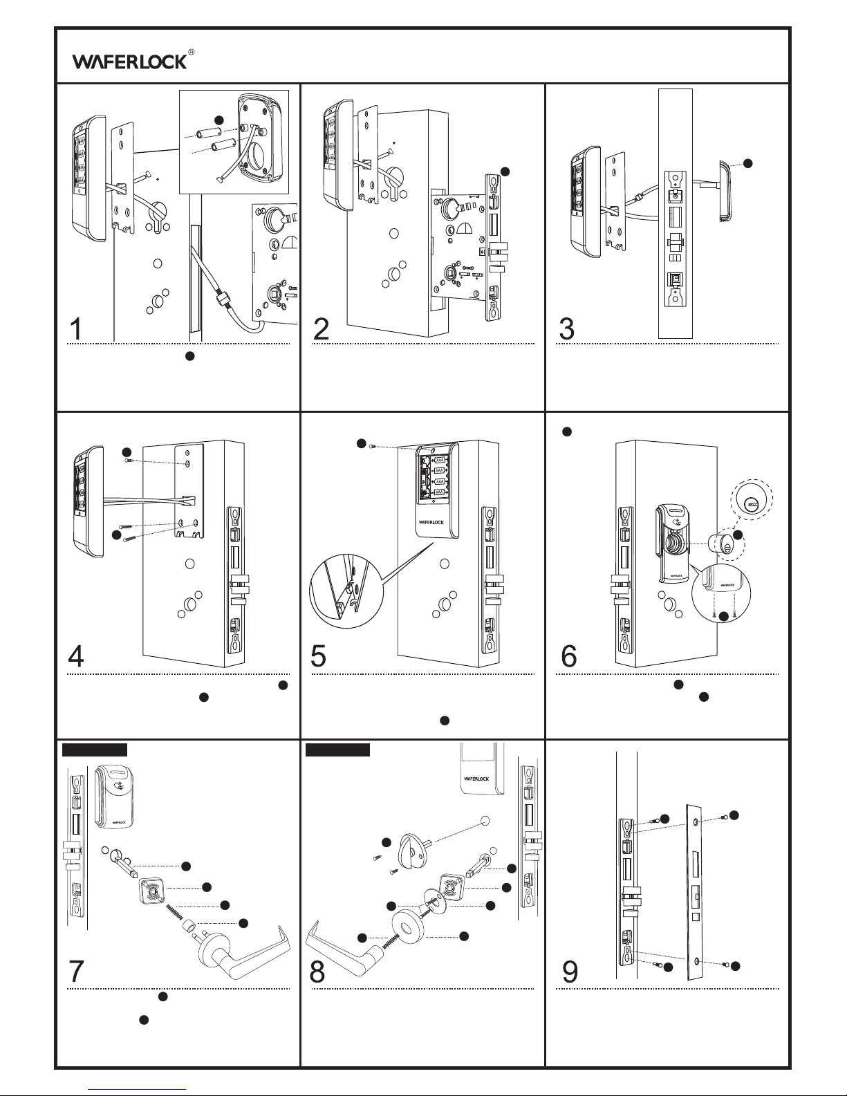
A. Fasten two stick screws to reader case.
B. Pull the inside control unit cables through plate.
C. Connect cables between control unit and mortise.
Slide the mortise into the door, and please be careful.
if the cable is clipped or connector is disconnected.
A. Fasten the plate and front reader with screws.
B. Fasten the mounting screw.
A. Stuff the extra cables into the door.
B. Slide the control unit from the bottom up and
fasten it on the plate.
C. Fasten the mounting screw for the control unit.
A. Install the ANSI cylinder.
B. Fasten the slide cover screws.
A. Place spring cage onto outside lever assembly
with arrows pointing in direction of lever rotation.
Insert spindle into hub of lock case.
B. Position outside lever assembly into post holes
of lock case.
A. Insert spindle into hub of lock case.
B. Place spring cage with arrows pointing in direction
of lever rotation and mounting plate(spring-mount
assembly) onto lock case and fasten with screws.
C. Cap inside rose over spring-mount assembly.
D. Insert inside spring into lever hole and tighten inside
lever bushing with spanner wrench.
E. Insert turn piece assembly and fasten with screws.
Fasten the mortise screws and cover by side plate
A. Pull the front reader cable through the door and
on top of mortise. Stick screws match the holes
on the door.
B. Connect cables between the front reader and
control unit.
21
21
10
14
13
13
10
24
24
18
L342 Installation Manual
www.waferlock.com
1
3
20
20
25
25
Outside Lever Inside Lever
23
23
A
22
22
13
10
11
17
18
18
17
19
9
12
12
15
 Loading...