

Page 1
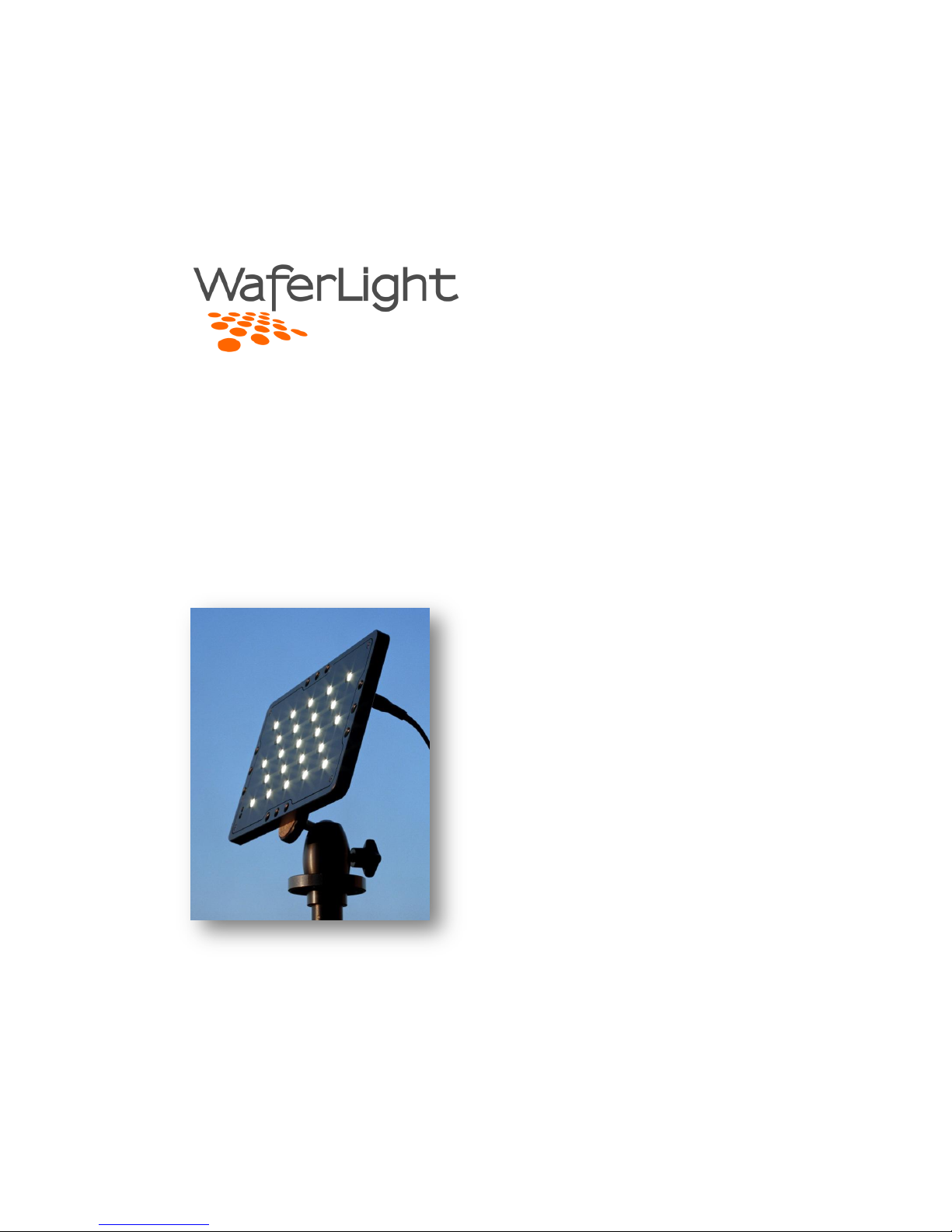
WL23 LED Light
User Manual
Page 2

Page | 2
Contents
Introduction...................................................................................................... 3
Contacting WaferLight ..................................................................................... 3
Key Features ..................................................................................................... 4
System ..................................................................................................................... 5
Operation ................................................................................................................. 6
Buttons ............................................................................................................. 6
Indicators ......................................................................................................... 7
Power input ...................................................................................................... 7
Infrared remote control ........................................................................................... 8
Activating IR control ......................................................................................... 8
Standard IR functions ....................................................................................... 8
Light group mode ............................................................................................. 8
Extended IR functions ....................................................................................... 9
Troubleshooting IR ........................................................................................... 9
Mechanical features ............................................................................................... 10
Soft box / diffuser .................................................................................................. 11
Specifications ................................................................................................. 12
WL23 Battery Pack ................................................................................................. 13
Battery replacement ....................................................................................... 14
Specifications ................................................................................................. 14
Accessories............................................................................................................. 15
Angle adapter ................................................................................................. 15
IR remote........................................................................................................ 15
AC adapter ..................................................................................................... 15
Remote battery cable ..................................................................................... 16
Warranty ................................................................................................................ 17
FCC NOTE ....................................................................................................... 18
Page 3

Page | 3
Introduction
Thank you for purchasing this state of the art LED illumination system. This lighting
unit is designed for many years of dependable operation and as a versatile tool that
can be extended or adapted to the many uses required in the lighting industry.
This user manual describes the features and operation of the WL23 LED light, the
WL23-BP battery pack and the system accessories.
Contacting WaferLight
Waferlight Systems Inc.
www.waferlight.com
Page 4
Page | 4
Key Features
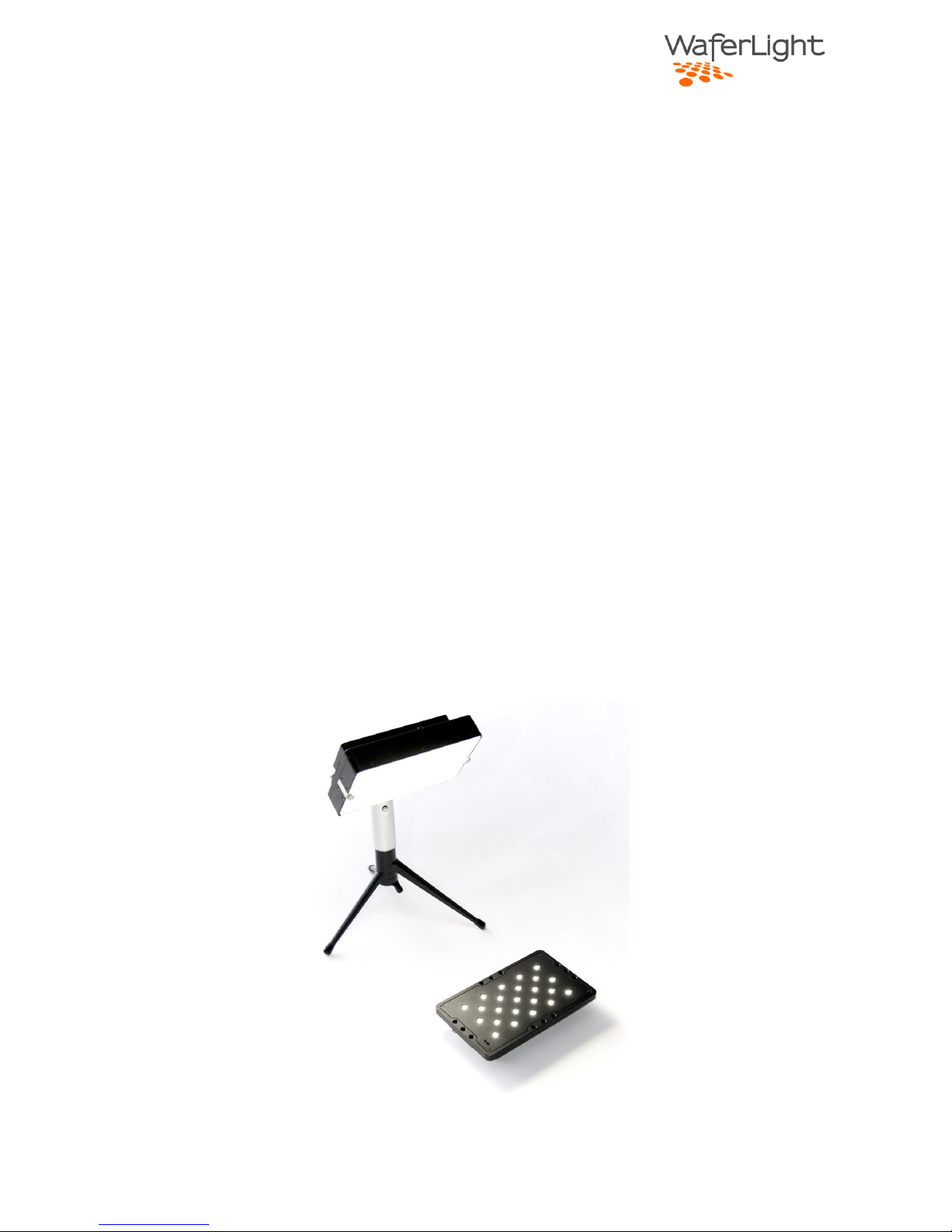
Key features include:
Very high light output at over 2000 lumens @ 5000K
Rugged ultra slim one-piece machined aluminum design
Versatile and extendable form factor with mounting holes along the edges of
the frame.
High power battery pack with user replaceable battery cells
Integrated soft box with replaceable diffuser film. Soft box can be removed
for maximum light output.
Can be powered from AC adapter or from other DC sources, such as existing
battery packs.
Available IR remote control for adjusting light output and power on and off
the light. The WL23 units can be set to respond in predetermined groups for
multi-light operation.
Page 5
Page | 5
System
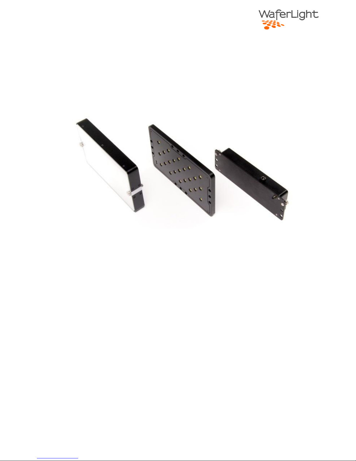
The WaferLight WL23 system consists of three main parts:
The Soft Box / Diffuser The Wafer The Battery Pack
Wafer
The wafer is designed with three ¼”-20 holes on each side of the frame. These
holes are used for mounting the soft box, battery pack and tripod/light stand, but
can be used for mounting any required accessory.
The integrated DC connector on the back side of the unit is compatible with
standard ø2.1/ø5.5mm DC-plugs. Any voltage from 5V to 24V can be used to power
the light but 12V is required for full power.
Soft Box
The soft box is mounted on the front of the wafer using two long ¼”-20 thumb
screws. By removing the thumb screws the protective front and the diffuser film
can be removed or replaced.
Battery pack
For flexibility there are three mounting holes on the battery pack. Any position can
be used with the short thumb screws. The pack features a built-in connector that
plugs into the DC connector on the Wafer.
Page 6
Page | 6
Operation
Buttons
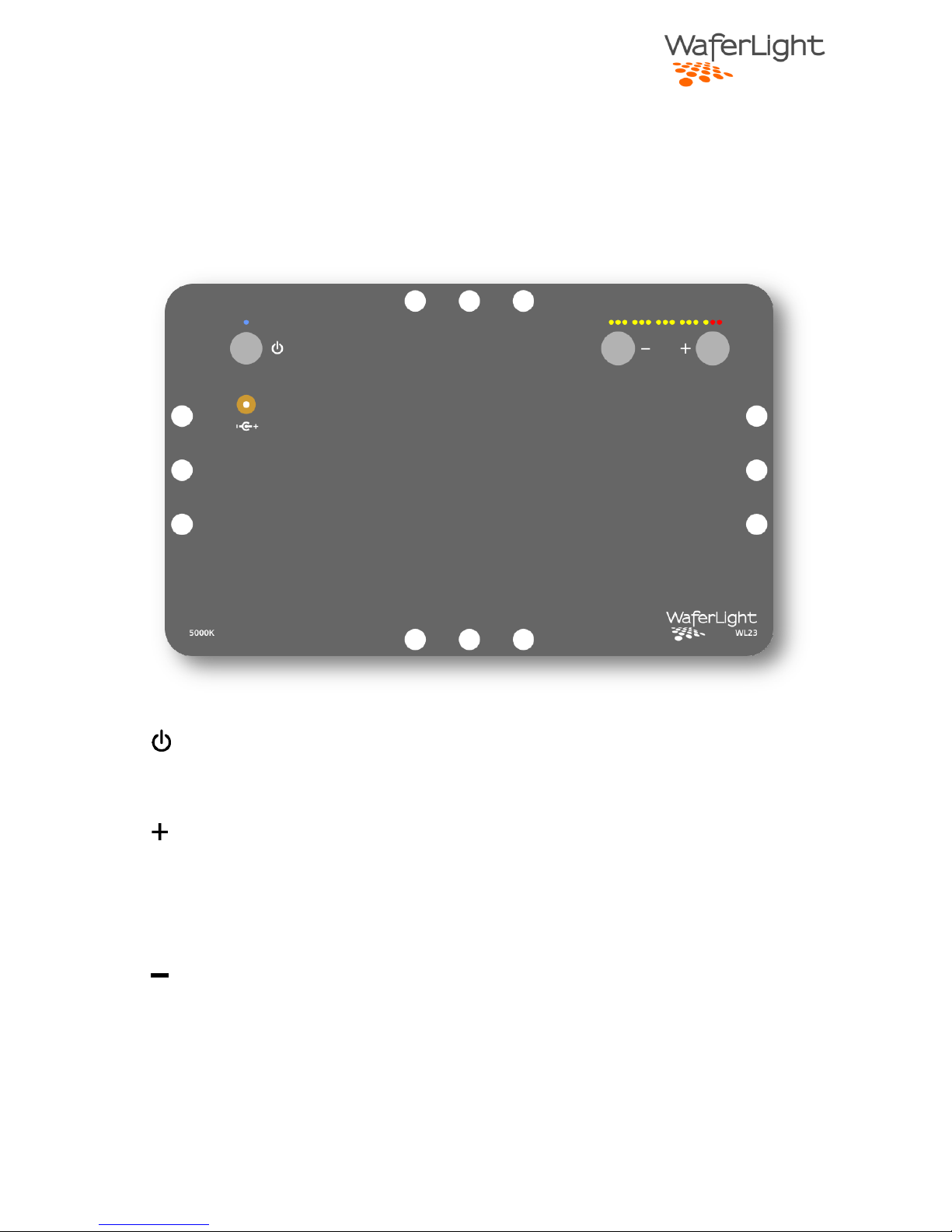
The WL23 unit has three integrated buttons that are recessed into the body.
Power button
This button simply turns on and off the light.
Up button
This button increases light output in 1/3 stop steps indicated by the row of LEDs on
the backside of the unit. Light output can be trimmed up in smaller steps by
holding this button.
Down button
This button decreases light output in 1/3 stop steps. Light output can be trimmed
down in smaller steps by holding the button.
Page 7

Page | 7
Indicators
When the unit is powered the blue indicator will be lit. The row of 15 LEDs
indicates the current light output.
Note that in the red zone (the two highest power levels) the light output may be
reduced automatically if the light gets very hot to protect the unit. This depends on
the ambient temperature and how long the light has been running. The blue LED
will start blinking if the temperature reaches a warning temperature of 55°C /
131°F and light output will be reduced at 60°C / 140°F.
Power input
The power input connector is integrated into the unit frame to protect the
connector from mechanical damage.
This is a standard ø5.5/ø2.1 mm DC-jack for maximum versatility. The light can be
powered from any power source from 5V to 24V, although to obtain maximum
output power 12V is required.
Page 8
Page | 8
Infrared remote control
The WL23 unit is equipped with a very sensitive IR sensor
on the front side of the unit. The optional IR remote can
control all the functions of the light.
Note that the default setting for the IR function is Off to
avoid accidental power turn-on while the unit is stored.
Activating IR control
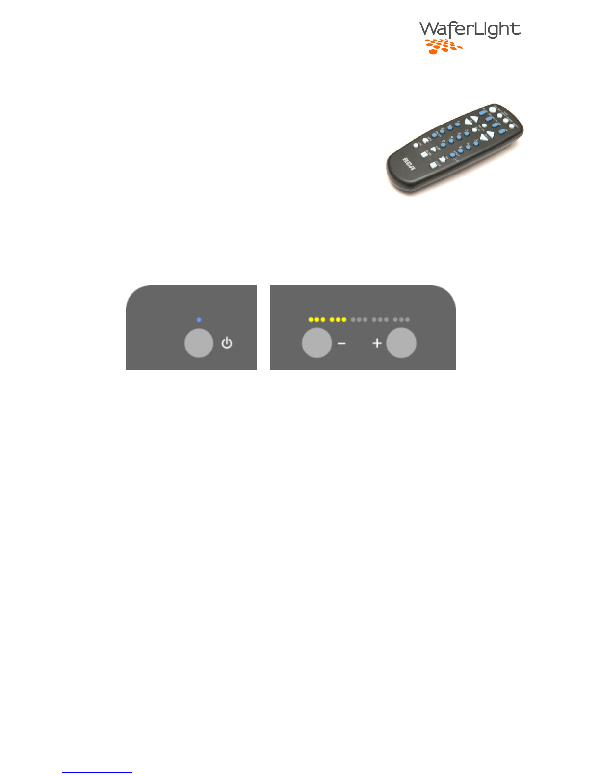
With power to the light press and hold the power button until the blue power
indicator is blinking. Now press the Down button (repeatedly) until six yellow
indicators are lit. When only one yellow LED is on the light is in light group mode 16 (details below).
Standard IR functions
ON-OFF Turns the light on and off
VOL Increases/decreases light output by 1/3 stop
CHAN Increases/decreases light output in small steps for trimming
MUTE Turns off the light
Light group mode
In light group mode several WL23 units can be controlled in groups. This is
convenient if the lights are used in larger lighting setups that need individual
remote control of each light unit.
Press and hold
Press until 6 indicators are on
Page 9
Page | 9
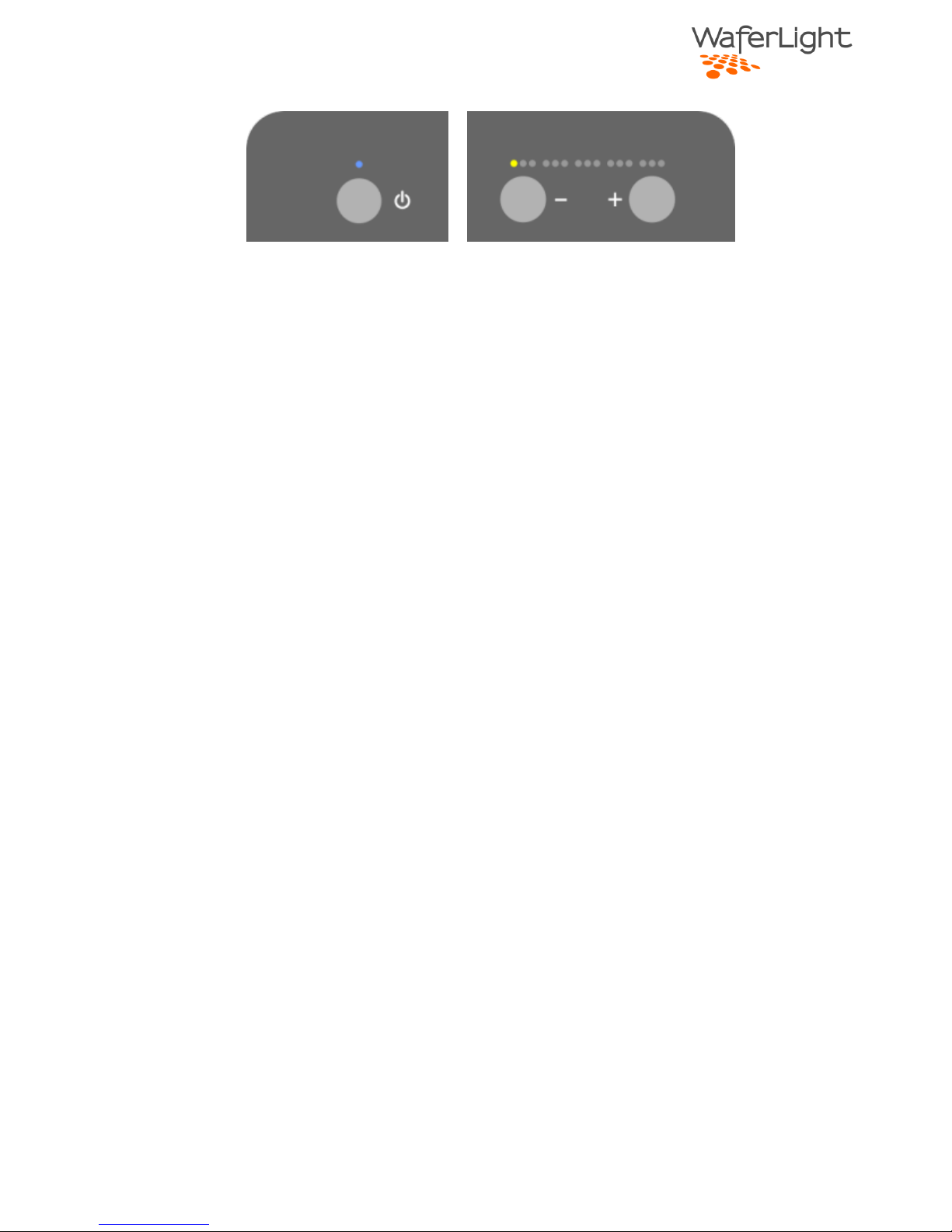
Six groups are available and they can be enabled by pressing and holding the power
button until the blue indicator is blinking and then pressing the Down (-) button
repeatedly.
If several lights are selected as the same group they will be controlled
simultaneously.
Extended IR functions
To control lights in groups the number button on the remote must be pressed first.
Press 1 to 6 for the group and then any of the standard commands.
To control all the light (turn off f. ex.) even though they are in groups, press the 0
button on the remote first.
Troubleshooting IR
If you are experiencing trouble getting the IR function enabled, please check these
steps:
1. Activate IR function on the main unit as described above
2. Install batteries in the remote
3. Press the TV button on the IR remote
4. Press and hold CODE SEARCH on the remote until the red indicator light and
enter the number 1454 (this programs the remote for correct function).
Press and hold
Light group 1 is selected
Page 10
Page | 10
Mechanical features
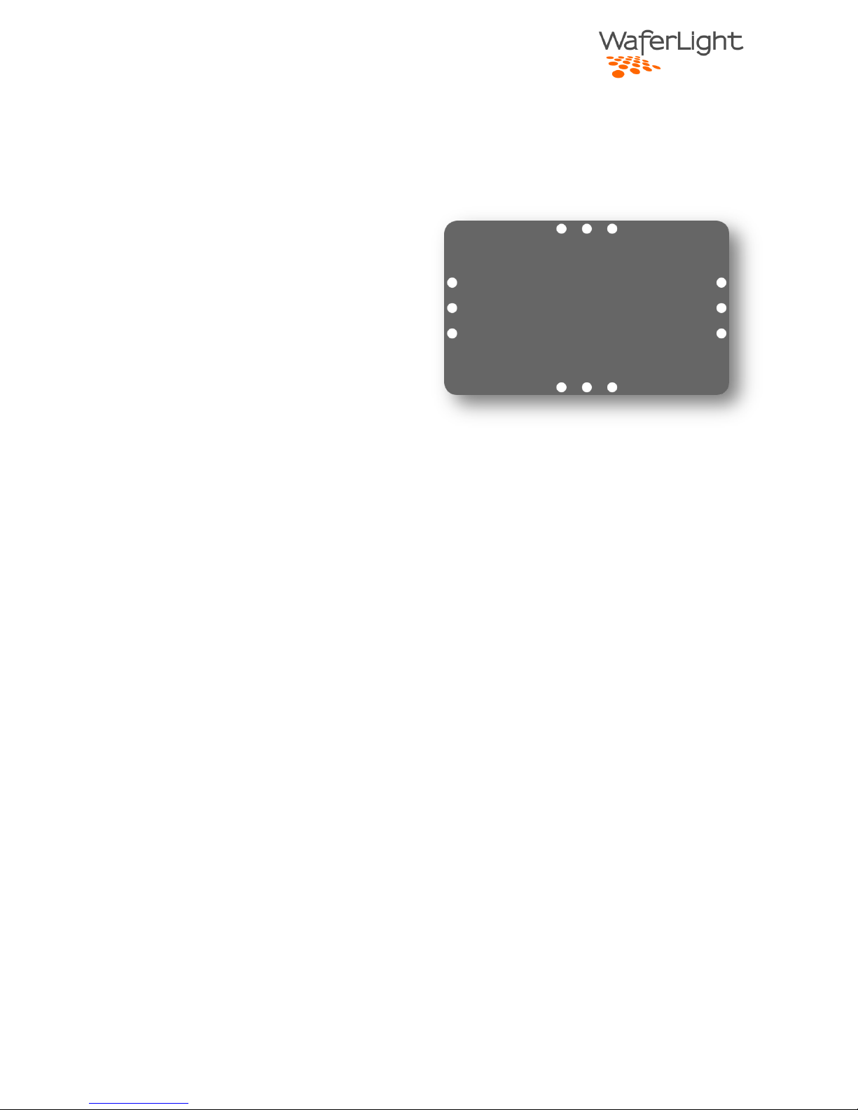
Along each edge of the frame are three mounting holes with standard 1/4”-20
threads. These holes are used for a
variety of mechanical add-ons:
Battery pack
Soft box
Stand adapters
Multi-panel brackets
Any other optional equipment
Our standard 1/4”-20 thumb screw fit
into these holes but any length standard
screw can be used for special applications.
Page 11
Page | 11
Soft box / diffuser
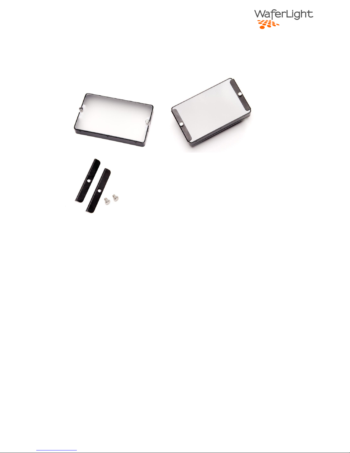
The soft box / diffuser in combination with the WL23 wafer will create a uniform
light source with excellent shadow quality. As with other parts of the system we
have designed the soft box to be modular and versatile.
Features:
The soft box can easily be removed from the wafer with two thumb screws.
The diffusion material can be replaced with other types of diffusion material
for specialty applications.
Two sheet holders are included with the system that can be used to hold
filters etc.
The front is made of high strength optically clear acrylic. If this part becomes
damaged in use it can easily be replaced.
The unit is designed to have minimal light leakage.
Page 12
Page | 12
Specifications
Description
Color Temperature
5000K
Input voltage
5V to 24V
Min 12V is required for full output power. Power setting is
automatically limited based on input voltage.
Input power
Typical power is approx. 30W at full power.
Input current
Max 3A.
Depends on input voltage and light setting.
Typical input current with the supplied 20V adapter at full
light output setting is 1.5A.
Total light output
Approx. 2300 lumens
Remote control
Light can be controlled in 1/3 stops or in small trim steps.
Power on/off function
Group control function.
Page 13
Page | 13
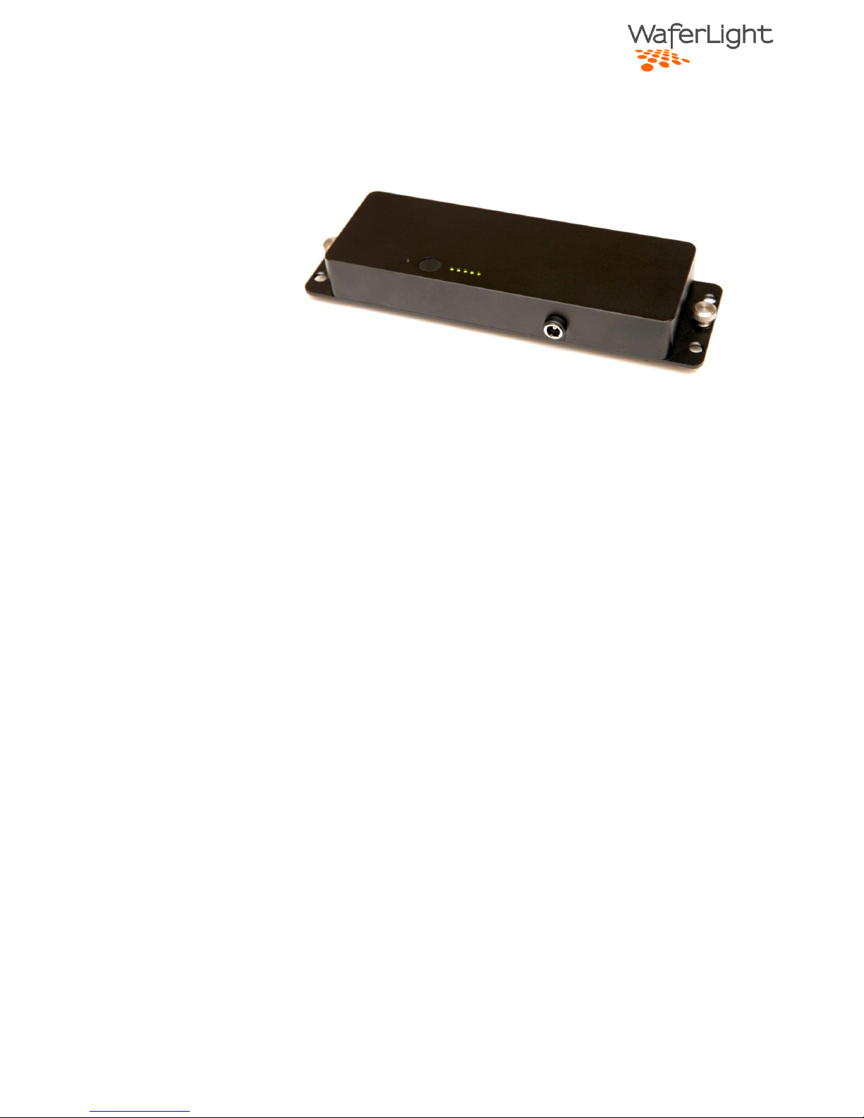
WL23 Battery Pack
Features of the battery pack
Made of durable machined aluminum
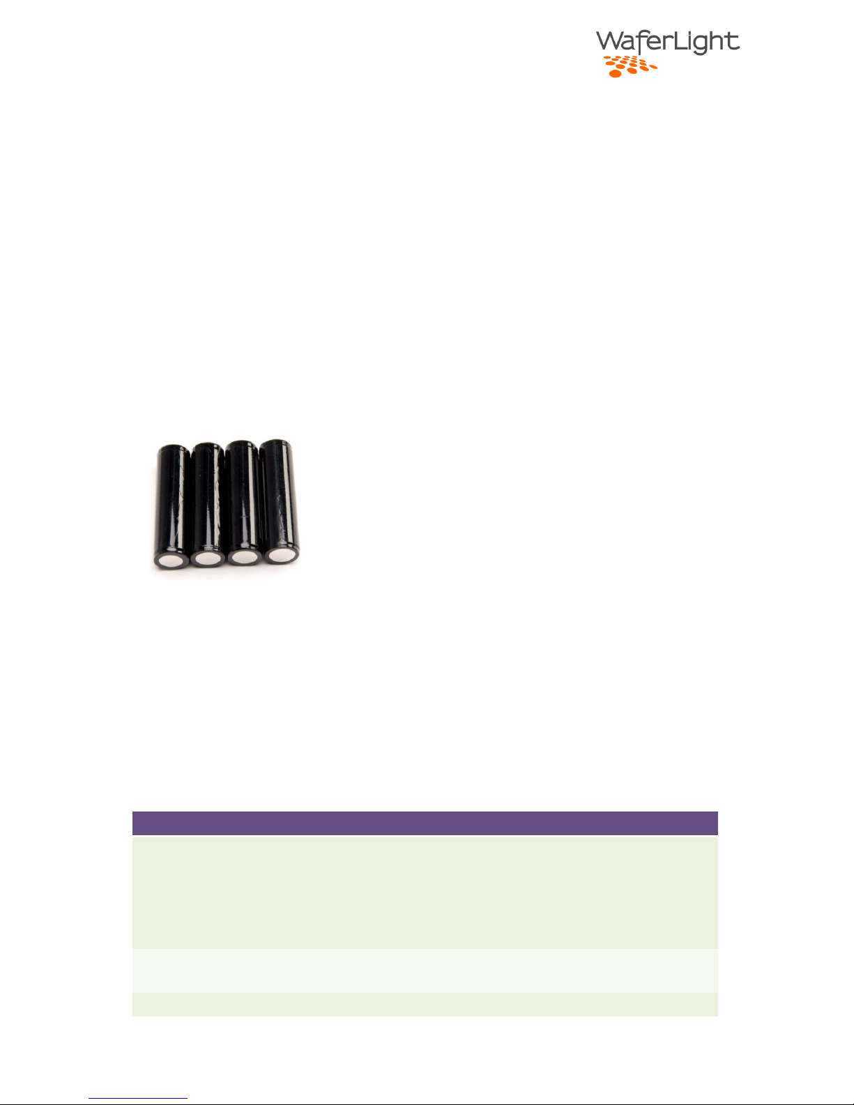
Holds four industry standard user replaceable 18650 protected cell batteries.
Built in battery charger. Battery can be charged on or off the light unit.
Any voltage from 5V to 24V can be used for charging.
The battery pack is made of durable machined aluminum and will power the WL23
wafer for a very long run time. The supplied batteries are high capacity, high quality
rechargeable lithium ion batteries with built-in cell protection. Due to this
protection the cells can be replaced by the user for lower cost and less waste.
The recommended batteries are Panasonic NCR-18650A with built in protective
circuit and are rated at 3.7V 3100mAh. Please see our list of accessories for
replacement batteries.
The pack has a built in charging circuit, so almost any power source that can supply
500mA can be used to charge the battery.
Built-in safety features.
If the temperature is above 50°C the red indicator will start flashing and at
55°C the battery pack will disconnect the output from the batteries.
Overcurrent protected.
Battery cell overcharge protection.
Note that if the battery pack is mounted on the light the power source will supply
the wafer directly if the voltage is above 17V. The supplied power adapter (20V)
can run the wafer at full power and recharge the battery at the same time.
Page 14
Page | 14
Check battery status
Press the button on the battery pack to check the remaining charge. Five lights
indicate fully charged and one light blinking is lowest charge. If no indicators are
shown the pack should be recharged to protect the battery from extended periods
of complete discharge.
NOTE:
The battery indicator may not show the correct battery status if the light is being
used at high power levels. For the most accurate indication, turn off the light
before pressing the battery button.
Battery replacement
To replace the batteries unscrew the four Philips screws on the back side of the
battery pack. Remove the battery cells carefully and replace with new ones. The
spring is the negative side of the cell.
Please use our replacement batteries or high quality Panasonic lithium cell with cell
overcurrent protection. Recommended battery type is Panasonic NCR-18650A with
cell protection.
Specifications
Description
Input voltage
5V to 24V
Will charge batteries at all voltages.
Note that input voltage must be larger than 17V (4 x Lithium Ion
batteries) to drive the WL23 light unit directly. If the voltage is
lower battery power will be used.
Input current
The built-in charger will draw between 0.4A at 0.5A at any input
voltage. For faster charging use a higher voltage.
Output voltage
Nominal 15V, 14V-17V depending on charge state.
Page 15
Page | 15
Accessories
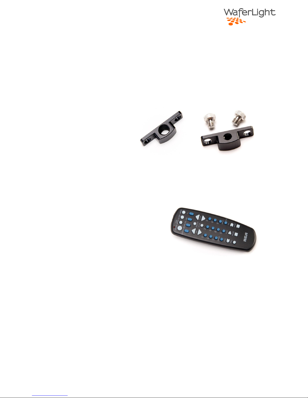
Angle adapter
This adapter is typically used for mounting the light vertically using a horizontal
tripod mount or light stand. Two models are available with different threads; 1/4”20 and 3/8”-16.
IR remote
The IR remove is a convenient controller for the light and allows use of multi-panel
lighting setups controlled in groups.
See IR remote chapter for instructions.
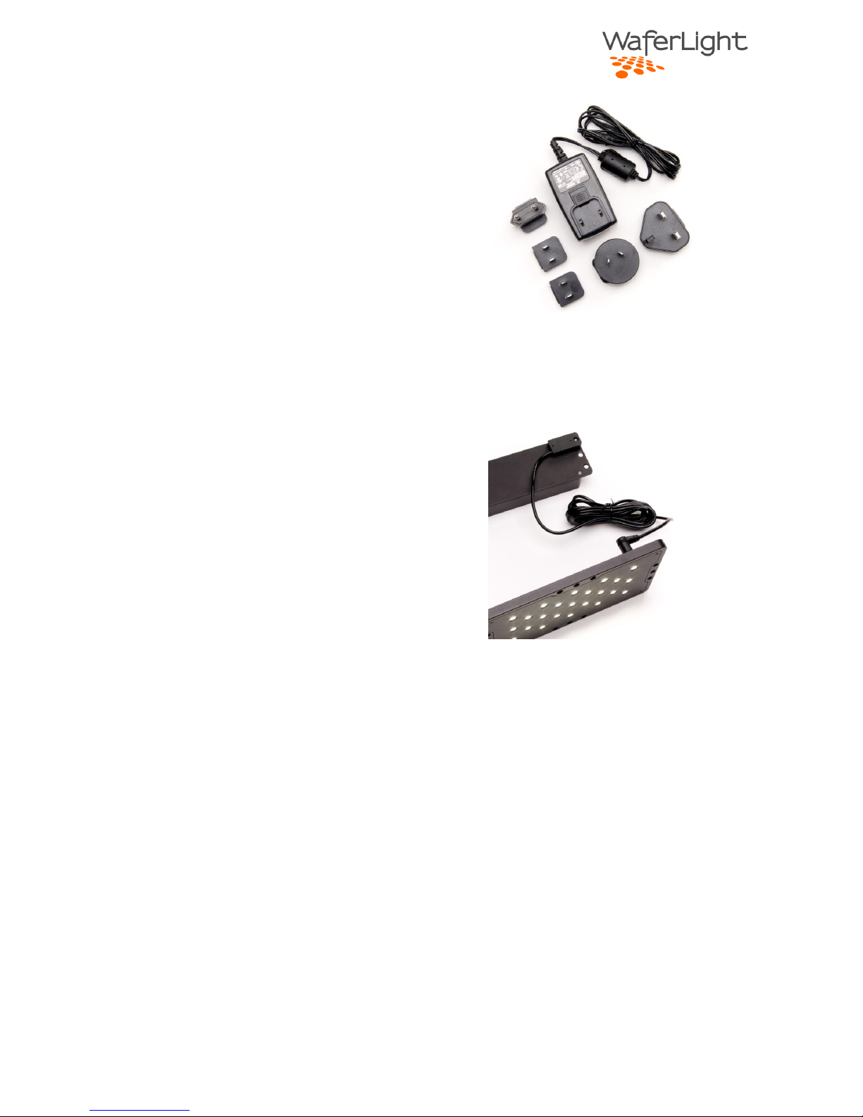
AC adapter
AC adapter will run the wafer at full power and charge the batteries at the same
time and features a small form factor and international blade-adapters for use
around the world.
Page 16
Page | 16
Remote battery cable
The remote battery cable lightens the weight of the light for on-camera use. The
battery pack can be safely stowed away in an equipment pocket.
Page 17

Page | 17
Warranty
Page 18

Page | 18
FCC NOTE
Note: This equipment has been tested and found to comply with the limits for a Class B digital
device, pursuant to part 15 of the FCC Rules. These limits are designed to provide reasonable
protection against harmful interference in a residential installation. This equipment generates,
uses and can radiate radio frequency energy and, if not installed and used in accordance with the
instructions, may cause harmful interference to radio communications. However, there is no
guarantee that interference will not occur in a particular installation. If this equipment does
cause harmful interference to radio or television reception, which can be determined by turning
the equipment off and on, the user is encouraged to try to correct the interference by one or
more of the following measures:
Reorient or relocate the receiving antenna.
Increase the separation between the equipment and receiver.
Connect the equipment into an outlet on a circuit different from that to which the receiver is
connected.
Consult the dealer or an experienced radio/TV technician for help.
Modifications not expressly approved by the manufacturer could void the user's authority to
operate the equipment under FCC rules
 Loading...