

Page 1
WAFER GSM-KEY REMOTE CONTROL UNIT
http://www.waferstar.com
GSM-KEY-3G
MANUAL
New version published from 2016
SHANGHAI WAFER MICROELECTRONICS CO.,LTD
Page 2
WAFER GSM-KEY REMOTE CONTROL UNIT
http://www.waferstar.com
GSM-KEY OPERATING INSTRUCTIONS
PRODUCT DESCRIPTION
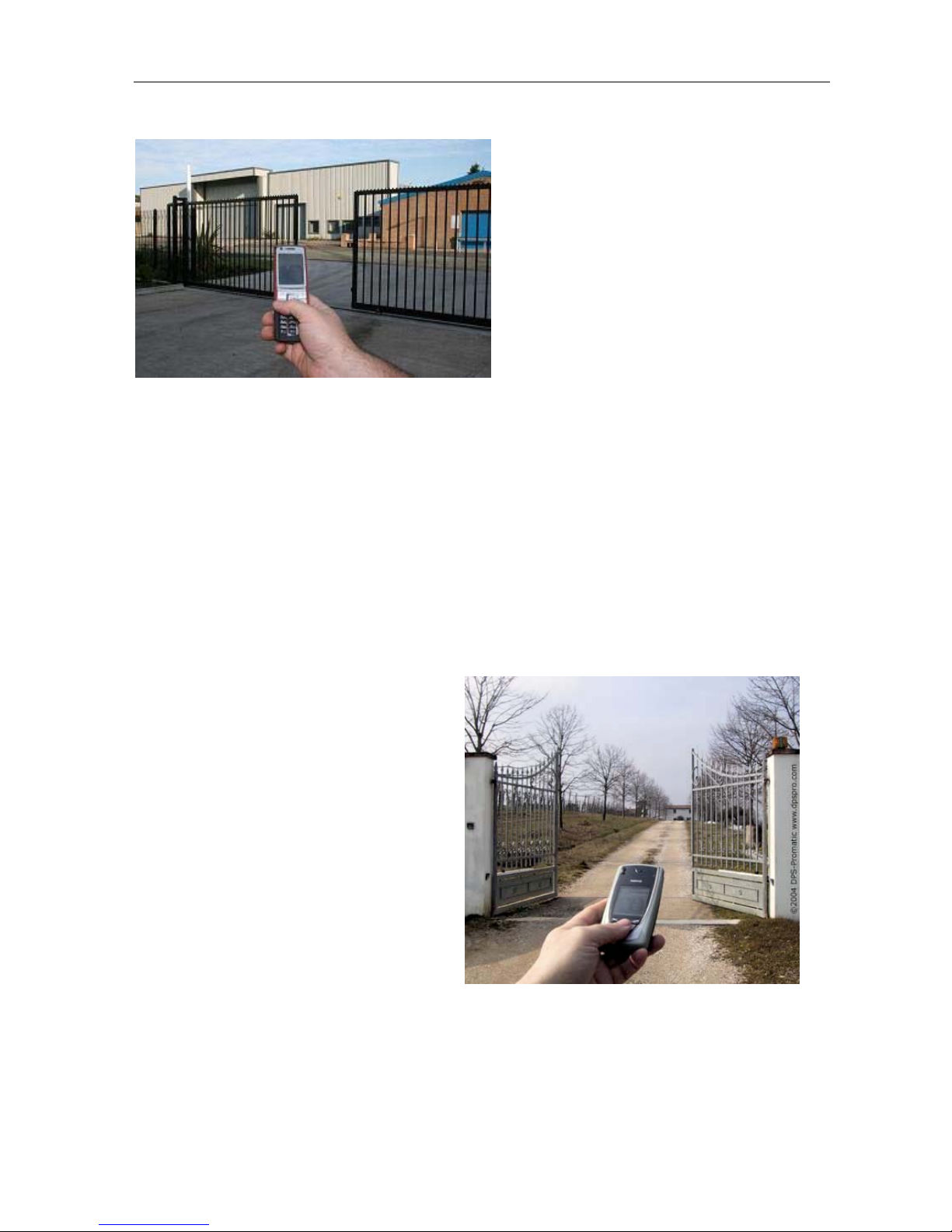
WAFER GSM-KEY is an electronic board with an on-board GSM modem.The purpose of
this device is to open an electric gate by means of a GSM phone.It has a door open relay whose
contact has to be connected in parallel with the button which opens the gate. It has a White List of
numbers who are enabled to open the phone, up to 2000. When the GSM-KEY receives a call, it
will check to see if the calling number is in the list. If it is in the list it will reject the call (so there
will be no charge -at least with today's charging procedures) and click the relay momentarily.
Also GSM-KEY has two alarm input port for the security detection.
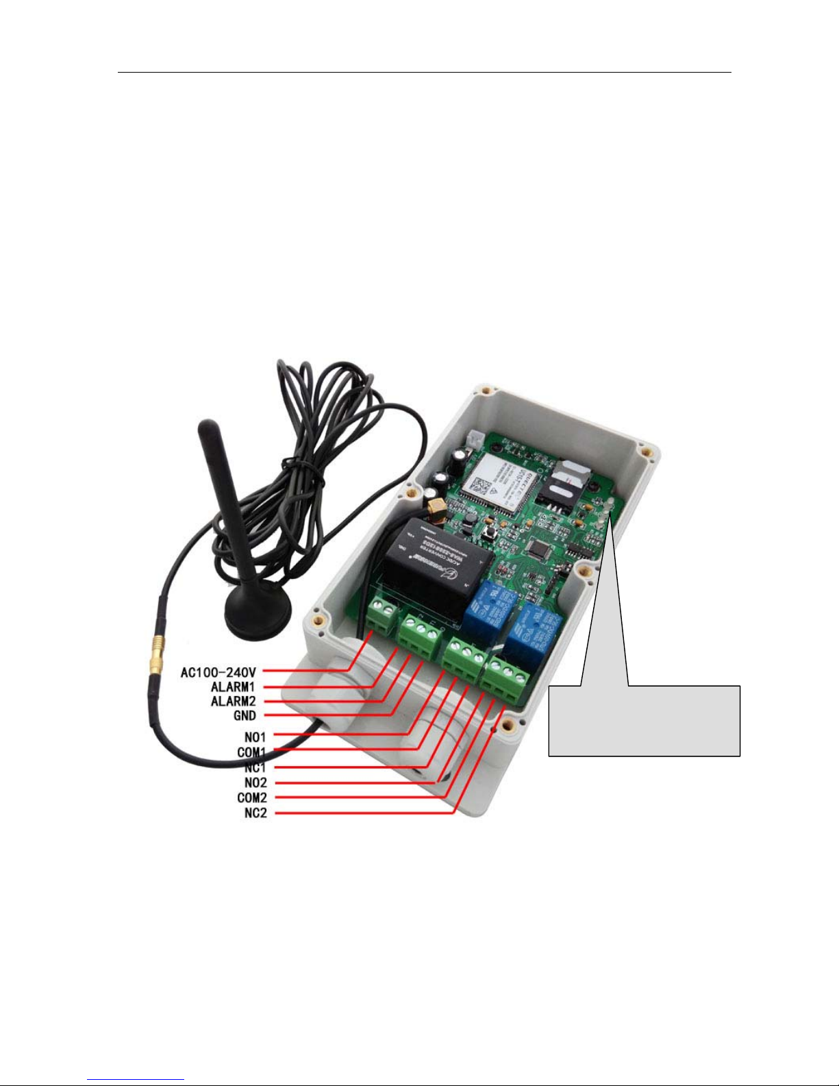
CONNECTOR DESCRIPTION
ADVANTAGES OF WAFER GSM-KEY
ˇ 2000 Number memory.
ˇ No call charges to operate.
ˇ No line rental using ‘Pay as You Go’.
ˇ Open gates prior to arriving.
1. 3G/GSM module LED (D6)
2. MCU LED (D4)
3. SMS Status LED (D2)
Page 3
WAFER GSM-KEY REMOTE CONTROL UNIT
http://www.waferstar.com
ˇ Let visitors and deliveries in remotely.
ˇ Caller ID confirmation for security.
ˇ Easy programming in minutes with your phone or PC software
INSTALLATION
To install the GSM-KEY, you need to connect the 2 wires of the relay contact in parallel with
the gate opening button. The relay contacts can stand 48V 0.5A maximum, this is enough for its
operation but don't try to switch higher voltages or currents. You should install the GSM-KEY
in a place where there is GSM signal coming from the operator you want to use. Check it with a
phone before proceeding with the installation. If you need to install the device in a place with little
signal, you may consider using an external antenna that we may supply as an option to be
purchased separately with 50cm cable.
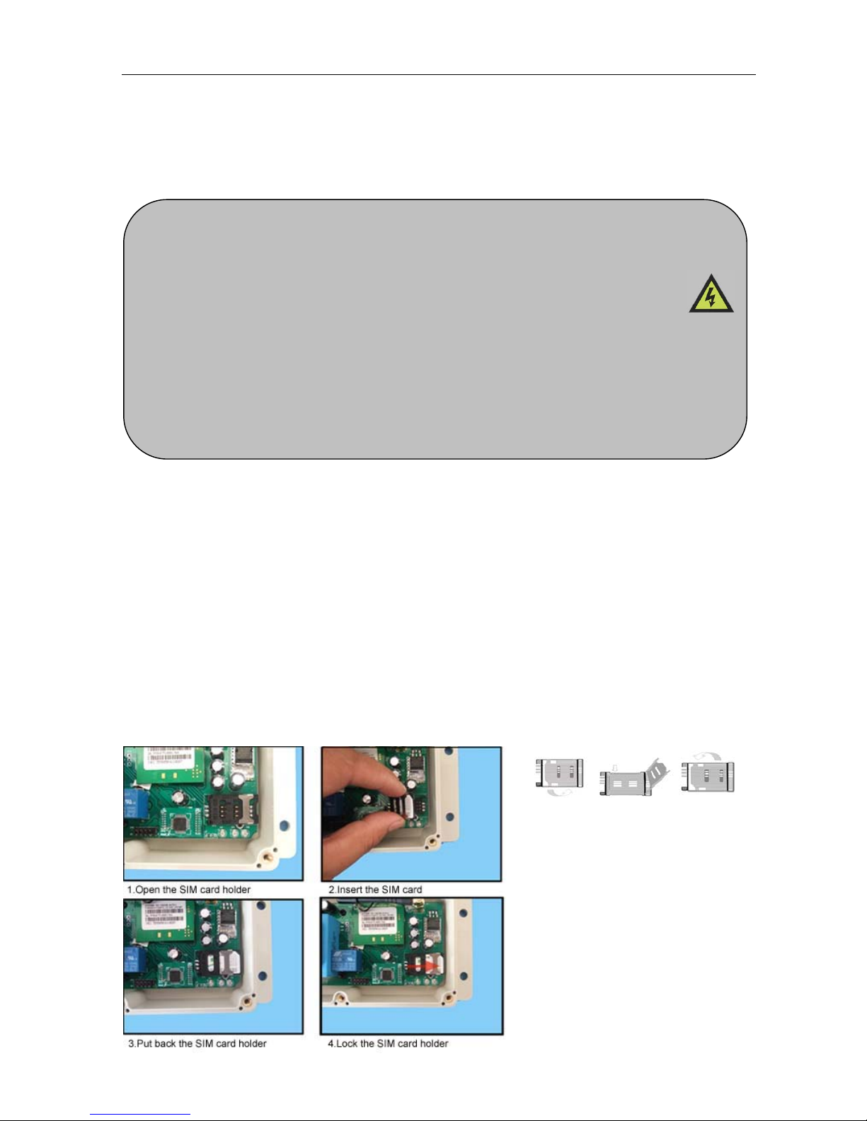
You should then insert the SIM Card of the operator you want to use with the right direction
according to the following pictures.
!Note! : You must remove the PIN request from the SIM before inserting it in the
unit, otherwise the device will not work. In order to do so, insert the SIM in a phone and
disable the PIN request (usually there is a security menu that enables you to do so).
Please read this entire manual before installation !Note!
z Take EXTREME care with the high voltage AC220V Power line installation
z In case of fault pull the mains adapter out from 220V network immediately.
z If device is connect into electricity, you couldn’t take off its cover.
z To maximise reception, install the GSM antenna in a prominent elevated position
if possible, and vertically mounted.
z The GSM unit requires mounting carefully in a weatherproof enclosure for out
door operation.
z Always ensure that the power is switched OFF before inserting or removing a SIM
card from its holder or damage will be caused to the module.
1.Slide back the SIM door and
lift it up
2.Slide the SIM Card into the
SIM door making sure that
the clipped corner of the SIM
card lines up with the clipped
corner of the SIM holder
3.Close the SIM door
4.Slide the SIM door to lock the
SIM card in place
Page 4
WAFER GSM-KEY REMOTE CONTROL UNIT
http://www.waferstar.com
GSM-KEY also comes with additional 2 Input.The inputs can be used to generate alarms
when triggered.For examples,you can can connect the saftey beam output to the GSM-KEY
Alarm1 and Alarm2 input.
WAFER GSM-KEY PROGRAMMING
You can program the GSM-KEY with SMS commands using your phone. It is safe to do so
because in addition to the fact that other people may not know the number of the SIM inserted in
it, we also use a Password that makes it impossible for anybody who doesn't know it to access the
system by chance.
Remember that commands must be CAPITAL LETTERS. It is PWD not pwd, CAP not Cap
etc. Don't add spaces or any other character.
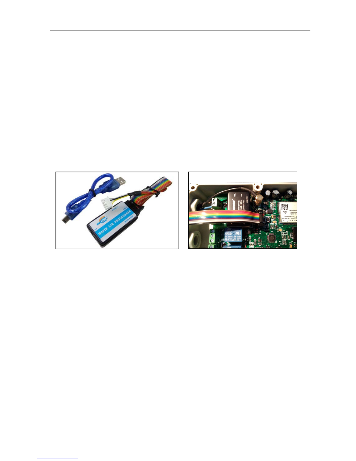
Some complicated Instructions,that cann’t be programmed by the phone SMS. That would
need to use the PC software to program and inquire the status of the terminal.
The bellow wire picture is to show how to connect the cable to the PC program connector
with the Program adapter.Please connect it in the right direction with the picture.
The following compand is used in the GSM-KEY :
#PWD: Password
#CAP: Change password
#WHL: White List (add or remove numbers)
#GOT: Gate pulse time
#ALARM: Alarm information setting
#MODE: Relay mode
#CSQ: Check Signal Quality
#SCA: Set service center address
#STATUS: Check status
Once you issue a command with an SMS, you will receive a confirmation SMS with OK
if everything is correct or Err if there is an Error.
Page 5

WAFER GSM-KEY REMOTE CONTROL UNIT
http://www.waferstar.com
GSM-KEY SMS COMMAND LIST:
#PWD Password.
This command must always come first 6 digits as a password.
The standard default one, when the device comes from the factory, is 123456.
We suggest that you change it, using the #CAP command.
In all the following examples we will use 123456 as an example of password.
#CAP Change Password.
Use this command to change the password with a new one that you will chose for your device
( don't forget it or you will have to send the unit back to us to reset it, and this has a cost )
The #CAP command must be issued 2 times to be sure you don't digit a wrong one.
OF course it must be preceded by the old password.
For example, to change the password 123456 into the new password 333444 you need to send the
following SMS:
#PWD123456#CAP333444#CAP333444
Acknowledge SMS: PWD SETUP OK
If you wrote correctly, or an Error message if you made a mistake.
If the old password is error,then conformation would be : Error Old Password
If you input two different new password,then reply would be : Error New Password,Please Check the
input again
#WHL White List.
This is the command that you will use most. it is used to add or remove numbers that are enab led
to open the gate into the White List. You can add up to 2000 numbers in the list. Every position
must be indicated in the command and we advise you to keep a list written somewhere to know
which numbers are in and in which position.
• To add a number, the syntax of the command is the following:
#PWD123456#WHL01=61143815
Acknowledge would be : WHL01 SET TO 61143815 OK
Where 01 is the position in the list and 61143815 is the number enabled.
Please note that it is possible to program up to a maximum of 10 digits for a number. If it has
more digits you should use the rightmost ones. For example, if your number is 33446665555 you
should program 3446665555. If your number appears as +85261143815 you should not program
the country code (+852). If your number has only 9 digits or less, it is not a problem. The
important thing is that you don't exceed 10 digits.
• To check which is the number in a place of the list:
#PWD123456#WHL01?
Acknowledge : WHL01 IS 61143815 OK
• To erase a number:
#PWD123456#WHL01=0000000
(or you can write over it another number you wish to add)
Page 6

WAFER GSM-KEY REMOTE CONTROL UNIT
http://www.waferstar.com
Acknowledge : WHL01 SET TO 00000000
List All numbers in the List
#PWD123456#WHL=ALL? (
PC)
Acknowledge :
WHL01 IS XXX
WHL03 IS XXX
WHL08 IS XXX
……
#SHL, #PHL, #QHL Special List.
Set from what time to what time you want these numbers operate (SHL maximum number is 250)
#PWD123456#SHL001=13564121668:1357(8:32-23:59)
Acknowledge : SHL001 SETUP TO 61143815:1357(8:32-23:59)
### SHL001 number would operate from 8:32 to 23:59 in Mon,Wen,Fri,Sun in every week.
Set from date to date you want these numbers operate (SHL maximum number is 250)
#PWD123456#PHL001=13564121668:100324-101012(8:32-18:26)
Acknowledge : PHL002 SETUP TO 61143816: 100324-100812(8:32-18:26)
### PHL001 number would operate from 8:32 to 18:26 from Mar.24th to Oct.12
Set how many times these numbers can operate (QHL maximum number is 100)
#PWD123456#QHL001=13564121668:12
Acknowledge : QHL003 SETUP TO 61143817:12
### QHL001 number would operate total 12 times,then would be expired.
• To check which is the number in a place of the list:
#PWD123456#SHL0001?
Acknowledge : SHL01 IS 61143815 OK
Or #PWD123456#PHL0001? #PWD123456#QHL0001?
• To erase a number:
#PWD123456#WHL01=0000
Or #PWD123456#PHL01=0000 #PWD123456#QHL01=0000
(or you can write over it another number you wish to add)
List All numbers in the List
#PWD123456#SHL=ALL? (Instruction Only for
PC)
Acknowledge :
SHL01 IS XXX
SHL03 IS XXX
QHL08 IS XXX
……
#QUERY Query the phone number in the WHL list. (PC$PHONE)
Query the phone number in the position of the WHL list,Special phone list or Alarm phone list
#PWD123456#QUERY=143535353 (PC$PHONE)
Page 7

WAFER GSM-KEY REMOTE CONTROL UNIT
http://www.waferstar.com
Acknowledge: QUERY RESULT: 143535353 AT WHL004
#ACM Safety control or free control mode setting. (PC$PHONE)
#PWD123456#ACM=ON
#PWD123456#ACM=OFF
ACM=OFF, Then any number can free control the device through the phone calling
ACM=ON, Then only the authorized number can control the device through the phone calling
#GOT Relay working output delay time. (PC$PHONE)(Only for NO.1 Relay)
When setup the GOT Timer,first you also need to setup the timer multiplier at millisecond or second
or minutes.
#PWD123456#GOT5000:MILLISECOND
#PWD123456#GOT500:SECOND
#PWD123456#GOT500:MINUTE
This command is useful in case you need to keep the Relay output working longer. The standard
time is 5 seconds (5000 ms). You can change it with the GOT command.
With the above command the delay time has been set to 5000 ms (5 seconds).
You can check what the current relay output delay time is with the command
#PWD123456#GOT? (PC$PHONE) (Only for NO.1 Relay)
Acknowledge: DELAY TIME IS 05000 MS
#ALARM Alarm setup
In GSM-KEY V2015,that Alarm01 is very important position,not only act as a alarm number,but also
working as the REPORT phone number, that means if you enable the REPORT function,then every report
event happen,then would send the REPORT SMS to this number
(1)You can setup the alarm phone number when have the alarm information input
#PWD123456#ALARM01=13818120592 (
PC$PHONE)
Where 01 is the position in the list
Acknowledge: ALARM01 SET TO 61143815 OK
When the number is seted to 000000,that means delete the number in this position
(2)
check which is the number in a place of the alarm phone list:
#PWD123456#ALARM01?
(PC$PHONE)
Acknowledge: ALARM01 IS 61143815 OK
(3)
List all numbers in the alarm phone list:
#PWD123456#ALARM=ALL?
(PC$PHONE)
Acknowledge: ALARM IS XXXXX:XXXX:XXXXXXX:0000:0000
(Will show total five numbers, if no effective number,that will be replaced with 0000 )
(4) Alarm mode setup (
PC$PHONE)
There are two alarm input ,you can set at PHONE or SMS
#PWD123456#ALARM-IN1=ON:PHONE:10,ALARM-IN2=OFF (
PC$PHONE)
Acknowledge: ALARM_IN1=ON:PHONE:10,ALARM_IN2=OFF OKAY
#PWD123456#ALARM-IN1=ON:SMS:300,ALARM-IN2=ON:PHONE:10 (PC$PHONE)
Page 8

WAFER GSM-KEY REMOTE CONTROL UNIT
http://www.waferstar.com
Acknowledge: ALARM_IN1=ON:SMS:300, ALARM_IN2=ON:PHONE:10
If at phone mode: when receive the alarm input,then will phone the number in the alarm phone list until you
reject the phone call or that will continue to phone the number again after the minutes setted.
If at SMS mode: When receive the alarm input,then will send the SMS to the number in the alarm phone list
until you send the SMS to PAUSE the alarm .
(5) Config the SMS TEXT :
(PC)
#PWD123456#UDI1:XXXXXX, UDI2:XXXXXX
Acknowledge: UDI1:XXXXXX, DI2:XXXXXX OKAY
(When the Alarm input is triggered,then will send the
SMS you already setted with this UDI command)
Check the text set
#PWD123456#UDI?
Acknowledge: UDI1:ABC1, UDI2:ABC2
#REPORT Report the system status change (PC$PHONE)
When setup to:
#PWD123456#REPORT=ON
Then any device status change would send the alarm SMS to Alarm01 number
#PWD123456#REPORT=OFF
No report for the device status change
#PWD123456#REPORT?
Check the REPORT setting status
#CSQ Check GSM signal quality. (PC$PHONE)
This command is useful to see what is the GSM network
signal level your GSM-KEY is receiving. It ranges from 0 to 32 (if it is 0 we doubt it will
ever answer...). You should have a signal above 12 to be sure of being able to open the
gate in any condition. Better if above 16. You should add an external antenna if this is not the case,
or eventually even change operator with another that serves your area better.
#PWD123456#CSQ?
Acknowledge: CSQ IS 26
#MODE Relay Operation Mode SETUP (PC$PHONE)
#PWD123456#MODE0
Acknowledge: RELAY SET TO MODE0
#PWD123456#MODE1
Acknowledge: RELAY SET TO MODE1
If set to MODE0,that is
Momentary pulse and If Config to MODE1,that is Ratchet relay
#STATUS Check the config information of the terminal (PC$PHONE)
#PWD123456#STATUS?
You will receive a Acknowledge with:
ALARM1=ON:SMS:040960,ALARM2=OFF:SMS:4352,GOT=05S,WHL=01,ALARM1=HIGH,
ALARM2=HIGH,BCPW=00,CSQ=10,RELAY1=ON,RELAY2=OFF
Page 9

WAFER GSM-KEY REMOTE CONTROL UNIT
http://www.waferstar.com
#OUT Control the Relay Output on or off (PC$PHONE)
#PWD123456#OUT1=ON or OFF
#PWD123456#OUT2=ON or OFF (If has the second relay output on board)
Config the RELAY Status when power Reset again
#PWD123456#POWER-RESET=11 (1 means ON ,0 means OFF when power on)
You will receive the following similar confirmation from the unit
POWER-RESET OK
#PWD123456#POWER-SAVE
You will receive the following similar confirmation from the unit
POWER-SAVE OK
Customized output control command TEXT: (PC$PHONE)
#REPLY SMS reply OFF or ON
#PWD123456#REPLY=ON
When setup to ON,then Device will reply the customized command after Relay is toggled
#PWD123456#REPLY=OFF
When setup to OFF,then Device will not reply the customized command after Relay is toggled
(This command is used to save the cost for user)
With these command you can customize the command to control your output.then would be easy
for you to understand the command
#PWD123456#OPEN1-TEXT#XXXX
#PWD123456#CLOSE1-TEXT#XXXX
#PWD123456#RLY-TEXT1#XXXX
If have the second output reply,then use the following command to config the second output
#PWD123456#OPEN2-TEXT#XXXX
#PWD123456#CLOSE2-TEXT#XXXX
#PWD123456#RLY-TEXT2#XXX
Check the Customized command text:
#PWD123456#OUT1-TEXT?
Reply:
OPEN1-TEXT=OPEN1,CLOSE1-TEXT=CLOSE1,TRIG1-TEXT=XXXX
#PWD123456#OUT2-TEXT?
Reply:
OPEN2-TEXT=OPEN2,CLOSE2-TEXT=CLOSE2,TRIG2-TEXT=XXXX
For example,you send the command:
#PWD123456#OPEN1-TEXT#GATE1 OPEN
Then you can use the simple SMS: GATE1 OPEN to switch on the output1 relay
#PWD123456#CLOSE1-TEXT#GATE1 CLOSE
Then you can use the simple SMS: GATE1 CLOSE to switch off the output1 relay
#PWD123456#RLY-TEXT1#GATE1 DIAN
Then you can use the simple SMS: GATE1 DIAN=5 to trigger the output1 relay for 5 second
Page 10

WAFER GSM-KEY REMOTE CONTROL UNIT
http://www.waferstar.com
#PWD123456#OPEN2-TEXT#GATE2 OPEN
Then you can use the simple SMS: GATE1 OPEN to switch on the output1 relay
#PWD123456#CLOSE2-TEXT#GATE2 CLOSE
Then you can use the simple SMS: GATE1 CLOSE to switch off the output1 relay
#PWD123456#RLY-TEXT2#GATE2 DIAN
Then you can use the simple SMS: GATE1 DIAN=5 to trigger the output1 relay for 5 second
PC Software interface:
Software language select
Select the right language according to your county,wafer will update the language step by setp.
(When Distributor need to support your local language,please contact wafer company)
COM Port parameters config interface and connect to the device
Before program the device through the PC,firstly you need to config the COM port paramters and
then connect the device to PC software.
Password is the PWD password, if no change,the initial password is “ 123456 ”
In the is program mode selection area, you have three type of the program mode to select
according your program adapter ordered ( you can confirm it from the following program adapter
pictures list )
1. Nomal program mode (RS232 program adapter and USB program adapter)
No selection of box of the RF-KEY mode and use modem
Input the right password,initial password is “ 123456 ”
2. RF wireless program mode ( RF program adapter )
Check the select box of the RF-KEY mode
Page 11

WAFER GSM-KEY REMOTE CONTROL UNIT
http://www.waferstar.com
Input the ID number of your device and password. This mode is only for the GSM-RFKEY
device. And each device have a special ID number.
3. GSM modem program mode (GSM modem program adapter)
Check the select box of the “ use modem”
For this mode,that is to use the SMS to program the remote GSM-KEY device. So you need to
input the “ Receive expired time ”, and also need to input the GSM-KEY device SIM card
number into the “ unit phone number ” text box.
For this mode, you also need to put another SIM card number in the GSM Modem
Normally the “ Receive expired time ” is setup to 2 minutes ( 120 seconds ),
The “ unit phone number ” is the SIM card number in the remote GSM-KEY device,not the
SIM card number in the GSM Modem.
RS232 and USB program adapter
Page 12

WAFER GSM-KEY REMOTE CONTROL UNIT
http://www.waferstar.com
Phone Numbers Setting interface:
(Before download the phone numbers,you need to SET the index to red color,then push the
button”Download All Phones”)
Special Phones Setting:
Page 13

WAFER GSM-KEY REMOTE CONTROL UNIT
http://www.waferstar.com
Alarm Phone Numbers Setting:
Log Interface
Page 14

WAFER GSM-KEY REMOTE CONTROL UNIT
http://www.waferstar.com
Miscellanelous Parameters Setting Page:
Unit Info: That is showing the Device edition of the design,you don’t need to change it
Unit Time; That is used to setting the timer of the GSM-KEY Device
Unit Password: That is used to change the control password
Reception: That is used to test the GSM signal quality of the site
Battery backup: That is used to setup the Power off alarm when power off.
Self clock update SMS: That is used to setup the phone number that is used to update the clock
Band selection: Not available
Relay Mode: That is used to setup the working mode
Relay Status: That is used to test the device through ON or OFF the on board relay
Alarm: That is used to setup the alarm mode of the two alarm channel
Alarm content: That is used to setup the alarm SMS content.
Note:
1. Gate delay cann’t be setup to “0”, then when you call the device, that relay output would not
work.
2. You should not change the BAND selection if you are not very familiar with the GSM device,
that would cause the function to stop to work
3. You can use the Relay Status selection box to check if that relay output can work well or not.
Battery backup function is not available on the normal Wafer products.
Page 15

WAFER GSM-KEY REMOTE CONTROL UNIT
http://www.waferstar.com
Troubleshooting
No LED is on after power up
· Check the power supply.
GSM LED D6 is not flash slowly or kept light continuesly (fast fast around 0.5s per time)
· GSM Signal is not good and cann’t register to GSM
· Check the SIM card.
· Check the PIN.
· Check the antenna connection.
· Select a place with a good GSM signal.
MCU LED is not flash slowly
· MCU is not working properly,Check the syster power
· Don’t move the GSM antenna above the MCU board
No tone can be heard after line off-hook
· Check the telephone line connection.
· GSM-KEY is not initialized properly upon start (approx. 10s after power up).
· GSM-KEY is not supplied with power.
No COM port on my computer
· COM port can be find in the computer device manager or not ?
· Our device has no relationship with the COM port can be find or not.
· If you use the USB to RS232 adapter,should check the drive is properly installed or not
What type of the USB to COM port adapter should order to work with GSM-KEY
· That would be better to order WAFER USB adapter
· Order the good quality USB adapter with FT232 chip inside
GSM-KEY does not communicate with PC
· Check the serial cable connection.
· Check the COM number setting on PC.
· Check the COM parameters (1200-115200 bps, 8N1).
· An incoming call is ringing on GSM-KEY
· An incoming Alarm is on processing by GSM-KEY
No Relay working tone can be heard when phone calling the device
· Check if your Control number is already setup into the device.
· GSM-KEY is not initialized properly upon start (approx. 10s after power up).
· If the GOT timer is setup to a very short timer ( normally should be more than 500ms )
Page 16

WAFER GSM-KEY REMOTE CONTROL UNIT
http://www.waferstar.com
This brochure provides an overview of the products and services of WEIFU GSM
Modules, For further information and queries kindly contact:
Email: wafer@waferstar.com
Web: www.waferstar.com
T el: 0086-21-51870528
Also accessible via our online Service Skype: wafer-service
If you need any sample order,please check our online store:
Http://www.wafer-shopping.com
Copyright 2008, WEFU GSM
V2016-4.0
 Loading...