

WAFE 350 EFS Quick Manual
PLEASE REMEMBER. The document also serves as a service book and warranty sheet (on the back).
QUICK GUIDE
WAFE 350 EFS Energy recovery ventilation unit
In every circumstances make sure you adhere safety regulations, warnings and instructions provided in
this guide and in the main manual. Their non-observence can lead up to personal injury or demage to
the unit. The latest version of the manual can be found in our document: www.wafe.eu/dokumenty.
In case you encounter a complex technical issue, contact WAFE customer servis immediately at +420 273
139 700. For easier problem identification, note the error code number (displayed on the unit display)
and the type of your unit (see the nameplate on the side of the unit).
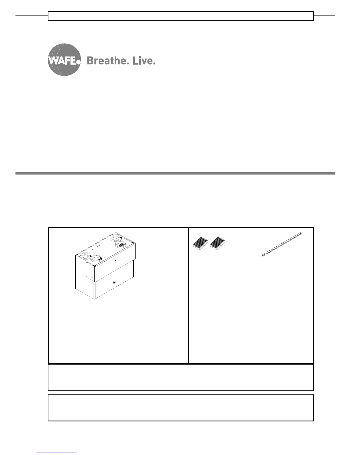
PACKAGE
INCLUDES
WAFE 350 EFS
energy recovery ventilation unit
M5 a F7 filters
(inside the unit)
Wall rail
User manual:
WAFE 350 EFS energy recovery ventilation unit
Brief guide:
WAFE 350 EFS energy recovery ventilation unit
Cardboard stoppers for air pipes (4x)
230 V/ 50 Hz cable
v 2.0

2
SAFETY INSTRUCTIONS
• Ventilation unit must be installed in accor-
dance with the general safety regulations valid in the place of installation.
• Ventilation unit must be installed, connec-
ted, operated and servised only by a properly
trained service technician, that is, a person
with appropriate education, experience and
knowledge of all the relevant regulations,
standards and potential risk and dangers involved.
• When laying the wires connected to the unit
it is necessary to make sure they are not exposed to any mechanical damage or detrimental enviromental effects and that they
do not interfare with the use of the space in
which the unit is installed.
• To prevent demage and injury when manipu-
lating with the electrical plug, pull the plug
head itself instead of its cable.
• The unit cannot be used by children under 8
years old and persons with reduced physical,
sensory or mental capabilities or lack of experience and knowledge, unless they are supervised or instructed on the use of the unit
in a safe way and understand the potential
dangers.
• Children must not play with the unit or per-
form the cleaning and maintenance of it.
TABLE OF CONTENTS
safety instructions 2
WAFE 350 EFS operation 3
Operation modes 3
Unit control 4
WAFE 350 EFS Maintenance 6
Maintenance by user 6
Technical support 7
Service book 8
WARRANTY AND RESPONSIBILITY 15
Warranty 15
Responsibility 15
Symbols used
Important information.
Unique feature differentiating your unit from
the competition
There is a danger of unit or ventilation systém
damage
There is a danger of personal injury
3
WAFE 350 EFS OPERATION
WAFE 350 EFS has been designed for your miximum comfort. After installion and initial setup of operating
values by WAFE technician (accoring to the construction project, see section WAFE 350 Installion / Installation and handover), the unit needs little to no attention.
Operation modes
INTELIGENT MODE
The unit analyses its surroundings and through optimal ventilation keeps the CO2 level as low as possible.
Recommended for general use.
Requires manual activation and deactivation through my.wafe.eu.
In case CO2 sensors are demaged unit will automatically switch to the forced Weekly mode.
WEEKLY MODE
The unit provides ventilation according to its factory settings (constantly except for workdays from 8AM till 4PM)
or according to its own time schedule set up at my.wafe.eu.
Alternative to recommended general use.
Requires manual activation and deactivation through my.wafe.eu.
For other than default factory setting login to my.wafe.eu web application, activate the Weekly mode and set your
own time schedule. Remember to confirm the new setting!
HOLIDAY
(OUT)
Unit is in low power mode and ventilates the house once a day.
Suitable when leaving the ventilated areas for extended periods of time.
Requires manual activation and deactivation through my.wafe.eu.
SLEEP
(STAND-BY)
The unit is in low power mode, communicates over the internet (if connected) but does not ventilate.
Turn on before unplugging from the power outlet.
Requires manual activation and deactivation through my.wafe.eu or via unit’s control panel.
Part of the transition to Sleep mode is a drying process: the unit closes its exterior flaps and the heat exchanger and
dries for 10 minutes. Unplugging the unit from the power outlet during this step might result in residual moisture
staying inside the unit.
CIRCULATION
The unit does not intake fresh air. The air circulates to spread out the heat or aroma in the building.
Activation and deactivation through my.wafe.eu.
DEHUMIDIFICATION
The unit primarily addresses the reduction of relative humidity in the building. EFS flap system remains in its position.
The unit must be connected to the condensate drain. When temperature below −𝟑℃, the unit can perform dehumidification function with SAFE DEHUM MODE.
Activation of DEHUMIDIFICATION function and SAFE DEHUM is performed by technician in SETUP menu.
OFF
The unit is unplugged from the power outlet: it does not ventilate and does not communicate over the internet
even if connected.
Not recommended: consider using the Sleep mode instead.
Switch the unit into Sleep mode (wait for the whole drying process to finish!) and unplug the cable.
ERROR
The unit does not ventilate and is awaiting the error resolution.
Automatically activated mode after encountering any errors.
After switching to Error mode, follow the steps in section WAFE 350 EFS Maintenance / Technical support.
Table 01: Operation modes
WAFE 350 EFS
4
Unit control
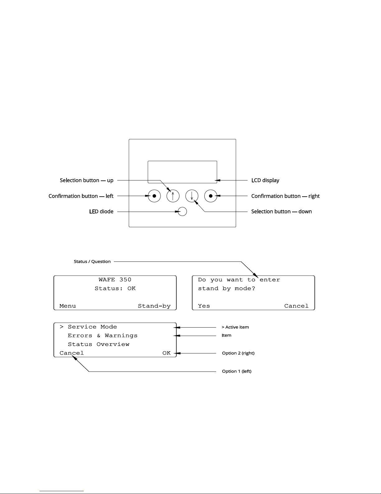
Control via LCD display
The unit’s control panel consists of an LCD display, four buttons with symbols and a LED diode.
Confirmation button—left/right (see Figure 02) are used to choose between Option 1 (Left)/2 (Right) (see
Figure 03). Pressing the Confirmation button always activates the option on the topmost line of unit display. To select a different option, scroll the menu by pressing Selection button—up/down so that your desired option is displayed on the first line.
Figure 02: Buttons on the control panel.
Figure 03:
The menu structure

5
Control panel LED diode has four light modes.
LED COLOUR
UNIT STATE
REQUESTED ACTIONS
Blue Glowing
The unit is on. Everything is ok.
Breathe. Live.
Yellow Glowing
The unit is on: incoming message
Check teh LCD display or my.wafe.eu web application.
Red Glowing
The unit is off: Error!
Check the LCD display or my.wafe.eu web application
and follow the instructions in section WAFE 350 Maintenance / Technical support.
Green Flashing
The unit did not change its state; green
flashing light signal an ongoing data
transfer.
Nothing. Do not unplug the unit from the power grid!
Table 02: LED light modes and related unit states.
Remote control via my.wafe.eu web application
Remote control of the unit is possible only if:
• The unit is connected to internet.
• You have been successfully registered as WAFE user and linked to your unit.
To control the unit remotely login to my.wafe.eu web application with your user identification data.
Any command entered through my.wafe.eu might take up to one minute to reach the unit.
First login to web application
After your account registration, you’ll receive an activation email with your login details. After you first log
in and choose a new password, the unit is ready for remote control via my.wafe.eu web application.
 Loading...