

Page 1
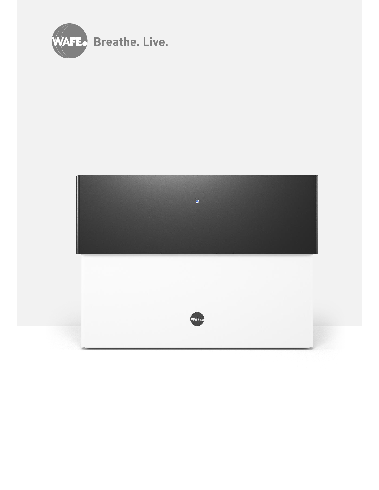
v 1.0
USER MANUAL
WAFE 350 Ene rgy Recovery Ventilation Unit
Page 2

Page 3

About the document | 3
Table of contents
About the document 3
Safety Instructions 5
Disposal 5
WAFE Intelligent ventilation specialist 6
Heat recovery story 7
Heat recovery basics 7
WAFE 350 Energy recovery ventilation 8
Unit summary 9
Unit parameters 10
Unit technical drawing 11
Unit exploded-view drawing 12
Unit anatomy 13
WAFE 350 Installation 17
Planning the installation 17
Installation and handover 18
WAFE 350 Operation 19
Operation modes 19
Unit control 20
Special cases 22
WAFE 350 Maintenance 23
Maintenance by user 23
Problem solving 24
Warranty and responsibility 25
Warranty 25
Responsibility 25
Notes 26
ABOUT THE
DOCUMENT
Information stated in the User manual:
WAFE 350 Energy recovery ventilation unit
(hereinafter “manual”) are to provide safe
and economically efficient operation of
WAFE 350 energy recovery ventilation
unit (hereinafter “unit”).
Read carefully, please.
Manual and its contents are owned by
WAFE s.r.o. For either partial or full publication, a written approval from
WAFE s.r.o. is necessary. Reproduction
for review purposes is allowed and there
is no need for official approval.
Manual is written, published and applicable exclusively for WAFE 350 unit.
Original version of this document was created in Czech language. The producer is
not responsible for any possible discrepancies due to the translation.
As we are constantly upgrading and improving our devices, your version of the
unit might look different than the one portraited in this manual.
The latest version of the manual can be
found in our document database:
www.wafe.eu/documents
© WAFE 2017. All rights reserved.
Page 4
4 | About the document
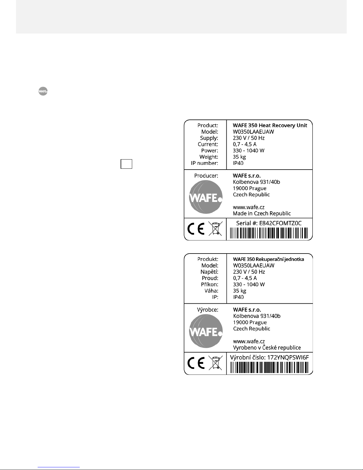
Type designation
Nameplate is used to identify the precise
model of the unit which is necessary for the
safe use of the product. The nameplate is
permanently located on the side of the unit.
Figure 01: An example of a unit
nameplate.
Symbols used
Important information.
Unique feature differentiating your
unit from the competition.
There is a danger of unit or ventilation
system damage.
There is a danger of personal injury.
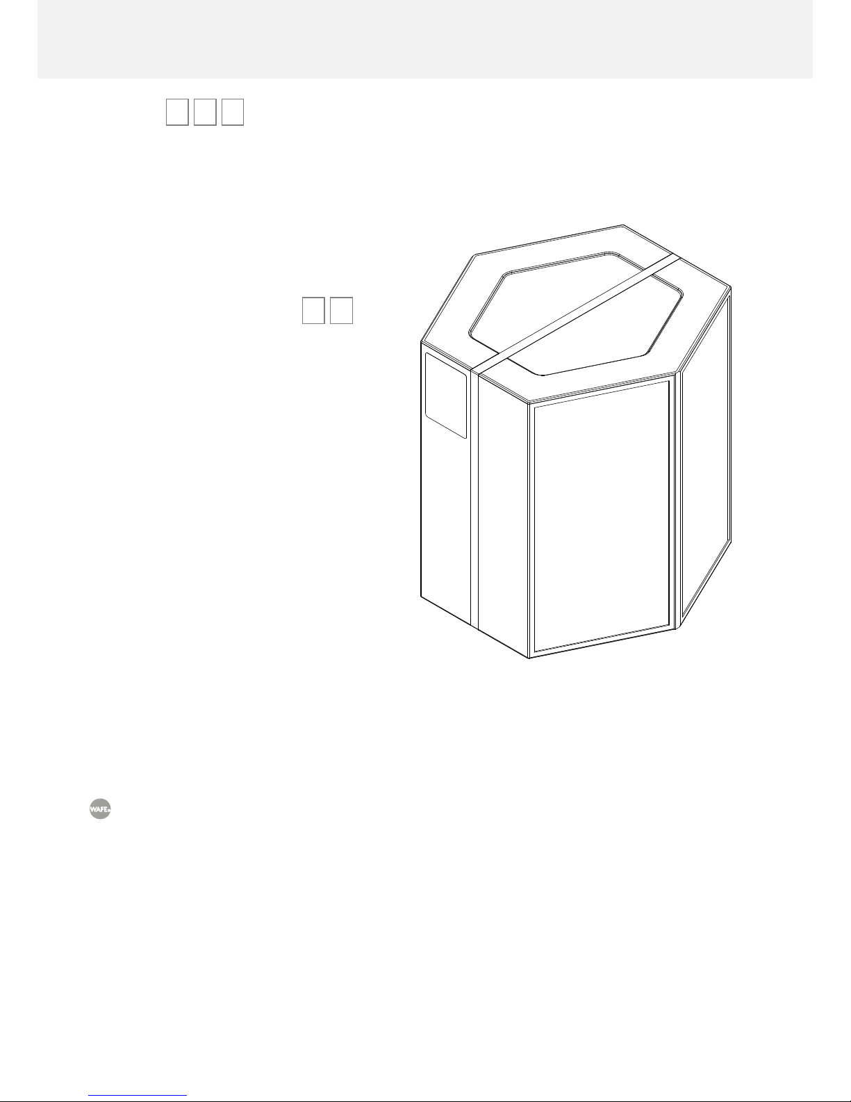
The numbers shown in box 123 refer to the
Figure 05: Exploded-view drawing of the unit
and Table 02: List of components.
Intended use
WAFE 350 energy recovery ventilation unit is
an air ventilation device with an active heat
and humidity recovery function designed for
comfortable and ecological ventilation management of living spaces up to an area of
250 m2 and out-side temperature of -30 to
+45 °C.
The unit can be used only for the purposes
for which it was developed and manufactured and for which it is technically eligible
in accordance with the conditions specified
by the manufacturer. Its design, implementation and technical condition adhere to
general safety requirements.
Page 5

Safety Instructions | 5
SAFETY INSTRUCTIONS
Before using the ventilation unit carefully read all the safety instructions below. By
compliance with the following, chances of mechanical or bodily damage are minimised. Manufacturer is not responsible for any damages resulting from non-compliance with these instructions.
• Ventilation unit must be installed in accordance with the general safety regulations valid
in the place of installation.
• Ventilation unit must be installed, connected, operated and serviced only by a properly
trained service technician, that is, a person with appropriate education, experience and
knowledge of all the relevant regulations, standards and potential risks and dangers involved.
• When laying the wires connected to the unit it is necessary to make sure they are not
exposed to any mechanical damage or detrimental environmental effects and that they
do not interfere with the use of the space in which the unit is installed.
• In case of damaged power supply, it must be replaced by manufacturer, his service tech-
nician or equally qualified person
• To prevent damage and injury when manipulating with the electrical plug, pull the plug
head itself instead of its cable.
• The unit cannot be used by children under 8 years old and persons with reduced physical,
sensory or mental capabilities or lack of experience and knowledge, unless they are supervised or instructed on the use of the unit in a safe way and understand the potential
dangers.
• Children must not play with the unit or perform the cleaning and maintenance of it.
Disposal
Dispose the package material in an environmentally friendly way. Once the life cycle of
WAFE 350 comes to its end choose an eco-friendly option for its disposal. The unit must not be
disposed together with a regular household waste. The unit has been classified according to
the EU Directive 2012/19/EU. The directive is valid throughout Europe and it sets a framework
for returning and recycling procedures of disposed appliances.
Page 6

6 | WAFE Intelligent ventilation specialist
WAFE
INTELLIGENT VENTILATION SPECIALIST
Welcome to the world of WAFE.
We are specialists on heat and energy recovery ventilation units. We do not produce radiators
or humidifiers or smart home control systems. We
focus on the one and only: designing and
manufacturing advanced ventilation units
that will operate flawlessly with minimal
service for many years to come.
We know that ventilation is something
you do not usually think of nor do you
want to. There’s more to life than that.
WAFE products are developed and built
so they would not interfere with your
daily routine; you do not need to fiddle
with numerous settings only to remem-
ber to unset them later. WAFE units oper-
ate in Intelligent mode and are equipped
with reliable sensors and electric circuits taking
care of unit’s internal logic. We assemble our prod-
ucts from quality Czech, German and Dutch components from reputable sources.
Thanks to our unique Enthalpic Flap System (EFS™) WAFE 350 reaches the highest efficiency
in its class at very low power consumption levels. Operating costs are minimal: you only replace
the filters. We sell a complete package, too: installation doesn’t require any additional expensive components you need to buy.
Here at WAFE - we think just like you do.
Petr Šec,
founder of WAFE
Prague, 30.3.2017
Page 7
WAFE Intelligent ventilation specialist | 7
Heat recovery story
Housing standards in the Western world are continually rising. It’s not only about comfort
anymore: ease of maintenance, ergonomics and low operating costs do matter, too. Above all
– we expect to live in a healthy and natural environment.
At first, we tried to solve this with better quality building materials, more efficient isolation and
airtight door and window systems. Some heat savings were achieved but it soon became apparent that a sealed off indoor environment like this is far from healthy and natural. Levels of
CO2 kept rising due to an accumulated exhaled stale air inducing weariness and a loss of focus.
Opening the window was the only solution. By doing so, however, we not only reversed any
previous heat saving benefits but allowed the city pollution and noise back into our homes.
Ventilation with heat recovery became the only suitable alternative.
Heat recovery basics
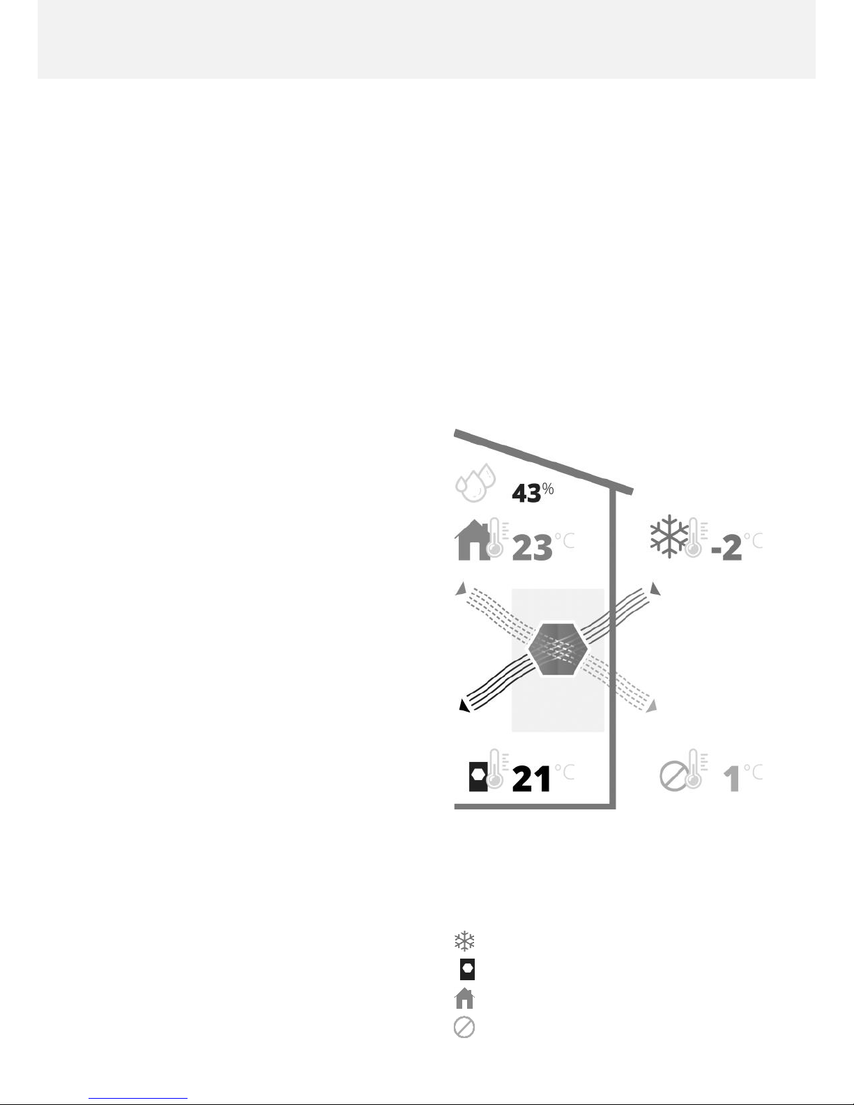
Heat Recovery Ventilation (HRV) efficiently
uses energy of waste stale air ejected out of
the building (with high levels of CO2) to
warm up the fresh air coming from outside,
thus creating a healthier and more comfortable environment for all the residents. In
summer, on the contrary, the air flowing
into the building is pleasantly cooled.
In addition to filtering out dust, smog elements and various allergens, superior
forms of ventilation systems —like
WAFE 350— recover not only heat but hu-
midity, too. Devices like these —called
Energy Recovery Ventilation (ERV) units—
save us money on heating costs and, more
importantly, create healthy and balanced
home environment.
Energy recovery ventilation is the
new standard in the construction of
modern houses, apartments and
commercial properties.
Figure 02: Flowing of air in and
out of heat recovery
ventilation system.
Outside temperature °C –2
Intake air temperature °C 21
Inside temperature °C 23
Exhaust air temperate °C 1
Page 8
8 | WAFE 350 Energy recovery ventilation
WAFE 350
ENERGY RECOVERY VENTILATION
Thank you for buying WAFE 350, our premium energy recovery ventilation unit.
Energy recovery ventilation (ERV) is a smart
way to ventilate your home without any significant loss of heat energy. WAFE introduces new concepts to the ventilation market and solves the most common industry
problems.
WAFE 350 energy recovery ventilation unit:
• doesn’t need to pre-heat the incoming
fresh air when temperatures are low,
hence saving even more on electricity
costs,
• keeps a natural and healthy levels of
humidity in your home even without
using expensive membrane heat exchangers,
• asks for a filter replacement only when
it’s actually necessary. Our competition
still uses timers with fixed replacement
intervals meaning that the filters are
often replaced too late or way too
early. Thanks to its inner sensors and
advanced logic WAFE 350 monitors a
real state of your filters,
• operates autonomously and does not
bother you with unnecessary and complicated functions.
WAFE 350 fulfils the high standards of modern living.
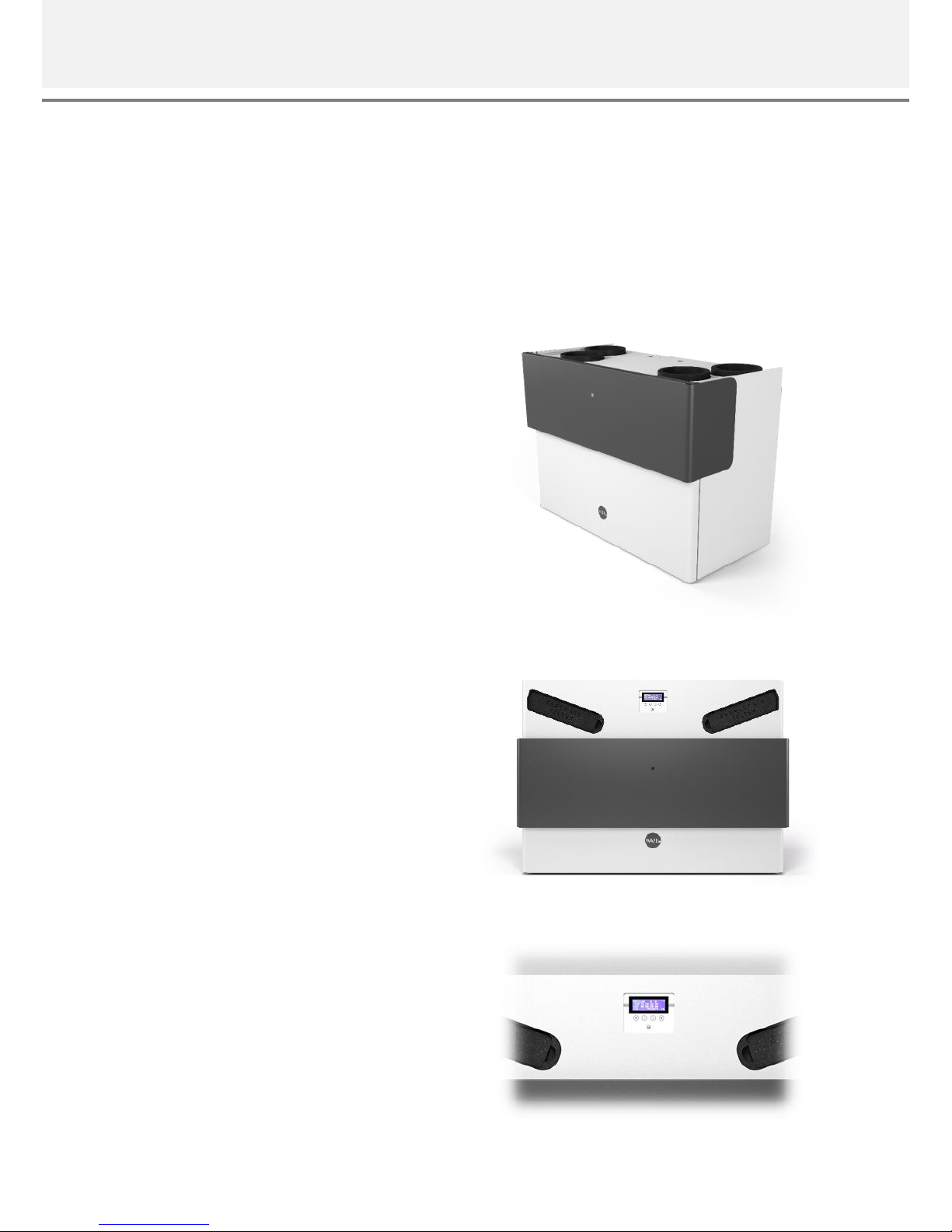
Figure 03: WAFE 350 ERV unit.
Page 9

WAFE 350 Energy recovery ventilation | 9
Unit summary
WAFE 350 Main benefits
Minimal required user interaction thanks to its
highly autonomous intelligence capable of analysing changes in its surroundings.
Practical and beautiful design made of the highest quality European components will inspire you
and faithfully serve you for years to come.
Enthalpic Flap System (EFS™) keeps healthy hu-
midity in your home and does not need expensive
pre-heating of intake fresh air during cold months.
Low investment costs – no more expensive acces-
sories. Everything needed for the operation is already included.
Low operating costs - maximum filter life expectancy, no expensive electric pre-heating and heat
exchanger that does not need to be replaced. Ever.
Wireless internet access gives the owner complete control over settings and costs of the unit and
enables automatic sending of notifications and error messages.
WAFE 350 Modes and functions
Intelligent mode
Sensors inside the unit analyse their surroundings, regulate the level of ventilation in the home
and maintain desired values of CO2 in the air.
Weekly mode
Unit runs in factory settings and ventilates constantly except during workdays between 8:00–
16:00. Changes in the schedule can be done
through my.wafe.eu web application.
Holiday mode [Out]
Unit is in low power mode and ventilates the
house once a day. Suitable when leaving the ventilated areas for extended periods of time. Requires manual activation and deactivation
through my.wafe.eu. //in development//
Sleep mode [Stand-by]
Sleeping unit is in low power mode, still communicates over the internet (if connected) but does not
ventilate.
Circulation
Suitable for localised heating or aromatherapy;
stops the intake of fresh outside air and only circulates the air between the rooms.
Night mode
When active, automatic initiation of Intense ventilation [Boost] (in Intelligent mode) and via external
button is disabled during evening hours (10PM–
7AM). Online initiation via my.wafe.eu is still possible. Night mode requires manual activation and
deactivation via my.wafe.eu.
Summer mode [By-pass]
The unit intakes outside fresh air into the house
without any heat exchange between the inside
stale air. This mode launches automatically during
summer months to prevent unwanted overheating
of buildings.
Intense ventilation [Boost]
In the occurrence of sudden decrease of air quality
(unpleasant smell, increased CO2) unit can raise
the intensity of ventilation for up to four hours.
This function is either activated automatically (in
the Intelligent mode), via separately installed external button or via my.wafe.eu web application.
Fireplace ventilation
Prevents a formation of negative pressure atmosphere when operating the unit along with the fireplace. //in development//
Page 10
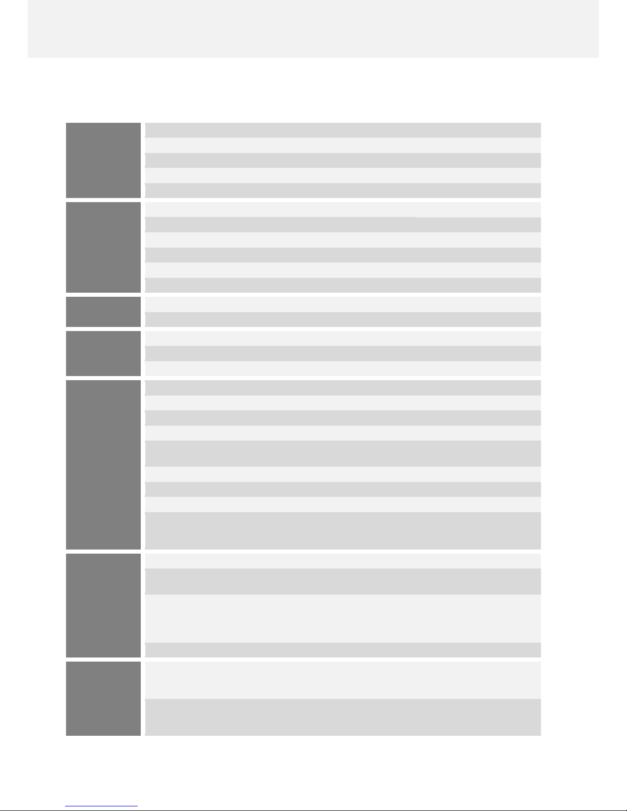
10 | WAFE 350 Energy recovery ventilation
Unit parameters
BASIC
PARAMETERS
Airflow
m³ / h
80–350
Temperature limits
°C
-30 to +40
Heat recovery efficiency
%
86–97
Humidity recovery efficiency
%
up to 95
External static pressure (ESP)
Pa
150–250
OPERATIONAL
PARAMETERS
Airflow reference
m³ / h
120
180
270
External static pressure (ESP) reference
Pa
100
100
100
Heat recovery efficiency
%
96,70
92,80
91,20
Acoustic pressure level
1 m distance
dB
35,4
38
41,5
Acoustic pressure level
2 m distance
dB
30,9
33,5
37
Power input
W
59,1
79,4
137,9
DESIGN
Weight
kg
35
Dimensions (w x h x d)
mm
1075 x 776 x 539
INSTALLATION
Installation room temperature
°C
5–40
Installation room relative humidity
% at °C
<70 at 22
Installation position
Vertical installation
COMPONENTS
Body Expanded polypropylene (EPP)
Heat exchanger
Plastic duct counterflow
Fans EC CF radial with forward curved blades
Flap system
Enthalpic Flap System (EFS™)
Filters
F7 fineness for fresh incoming outdoor air
M5 fineness for stale exhaust air from the building
Control panel
Analog buttons and 4-line display
Sensors
Pressure, temperature and humidity, CO₂
Sheathing
Aluminium plates with powder coating
Accessories
(upcoming — sold separately)
INELS wall remote control
Aromatizer
SIGFOX Internet of Things network connectivity
CONSTRUCTION
READINESS
Ventilation
mm
DN 160/200 mm (inner/outer diameter)
High voltage
230 V AC, 50 Hz
+ 2 m cable with a standard euro connector
Low voltage
(optional)
Ethernet / RJ45 + CAT5e cable
Potential free (dry) one-way button for Intense
ventilation [Boost]
24 V DC servo drive for façade flaps
Sanitary infrastructure
(optional)
Condensate outlet with 5/4" external thread
OPERATIONAL
LOGIC
Modes
Intelligent mode
Weekly mode
Sleep mode [Stand-by]
Holiday [Out]
Summer [By-pass]
Night mode
Functions
Intense ventilation [Boost]
Fireplace ventilation
Circulation
Table 01: Parameters of the unit.
Page 11
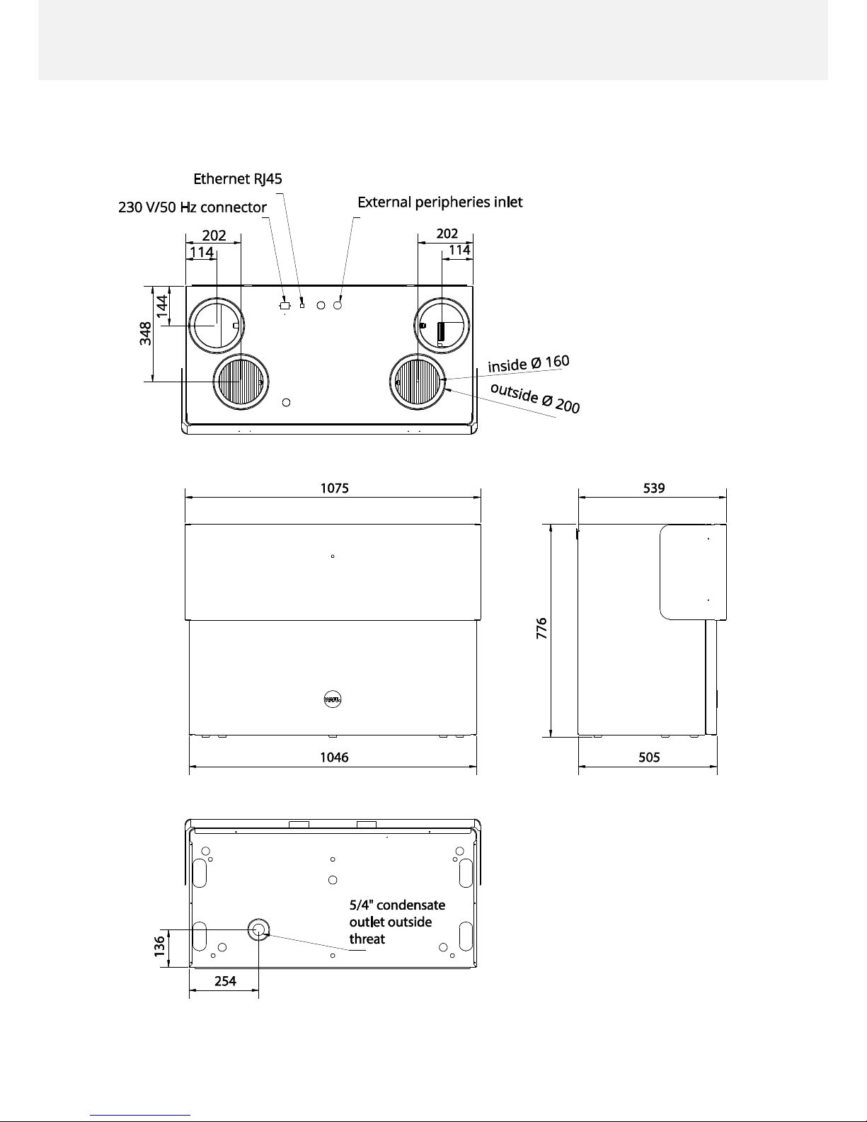
WAFE 350 Energy recovery ventilation | 11
Unit technical drawing
Figure 04: Technical drawing of the unit.
Page 12
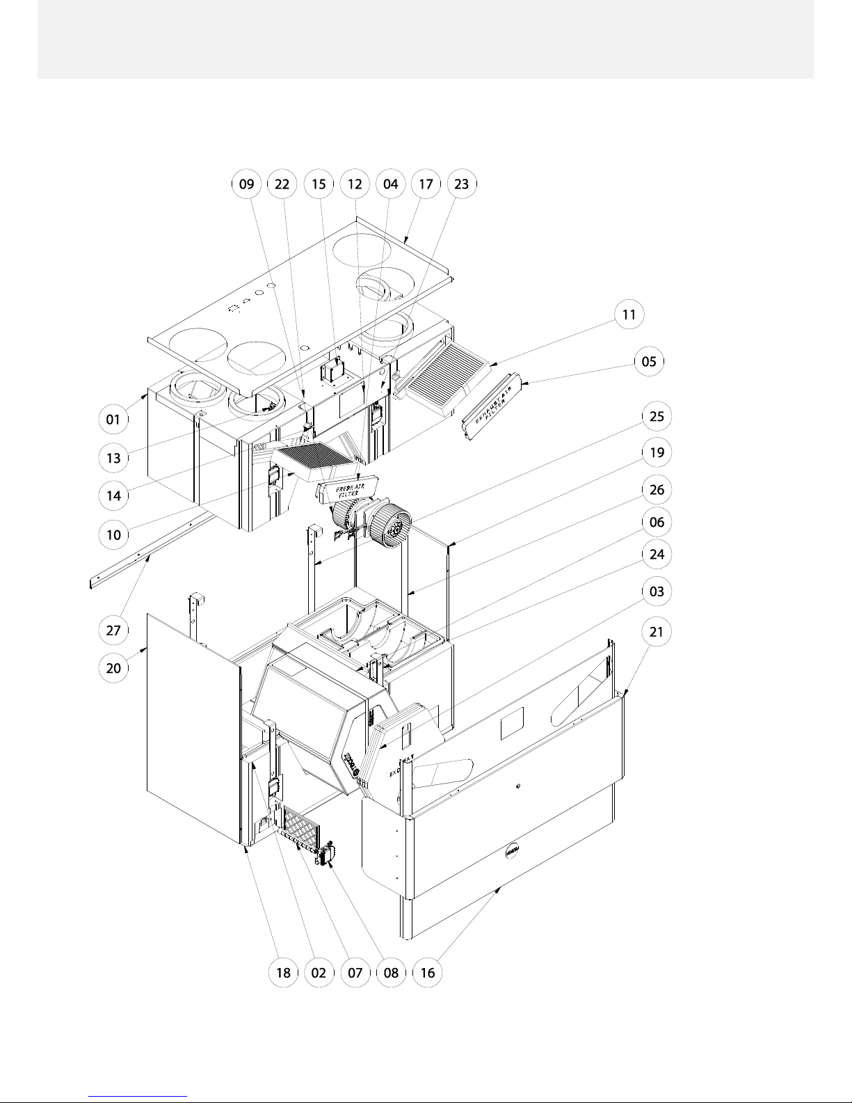
12 | WAFE 350 Energy recovery ventilation
Unit exploded-view drawing
Figure 05: Exploded-view drawing of the unit.
Page 13
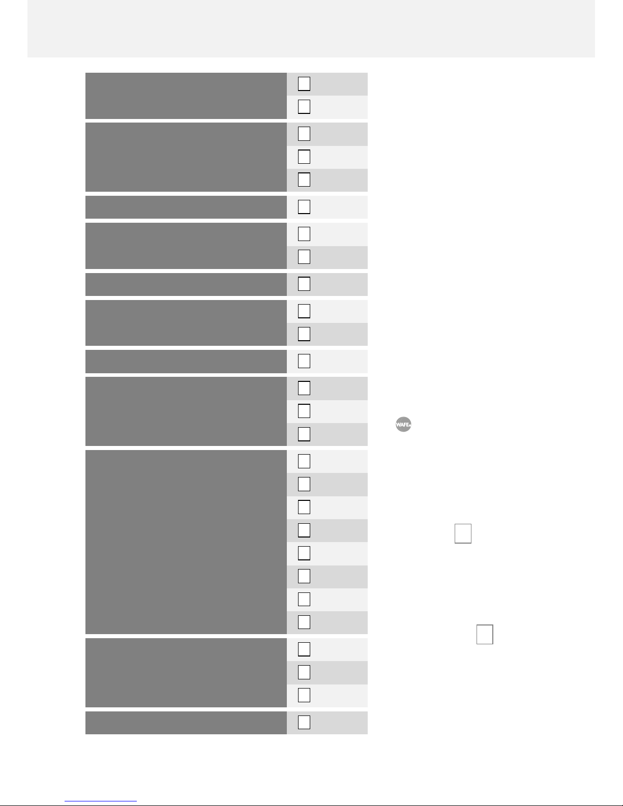
WAFE 350 Energy recovery ventilation | 13
Unit anatomy
Body
The internal construction of the
unit is made of high quality expanded polypropylene (EPP)
body which guarantees perfect
tightness and sound and temperature insulation without
thermal bridges. It is a modern
and premium alternative to now
obsolete metal constructions.
Manufacturing process of all
WAFE EPP bodies includes injecting a fine granulate under
high pressure into massive aluminium moulds and subsequently hot steam baking them.
The result is a complex
casting that allows us to
offer the lightest, most
compact energy recovery
ventilation unit on the
market in its category.
Top body 01
The top EPP body consists of
four air pipes and a space for
mounting unit’s electronic sys-
tems.
Bottom body 02
In addition to firmly anchoring
unit’s mechanical parts the bottom EPP includes a condensate
outlet in case you plan to use it.
BODY, TOP
01
1x
BODY, BOTTOM
02
1x
STOPPER, HEAT EXHANGER
03
1x
STOPPER, FILTER — FRESH AIR
04
1x
STOPPER, FILTER — EXHAUST AIR
05
1x
HEAT EXCHANGER
06
1x
FLAP
07
4x
FLAP SERVO DRIVE
08
5x
VENTILÁTOR
09
2x
FILTER — FRESH AIR
10
1x
FILTER — EXHAUST AIR
11
1x
CONTROL PANEL
12
1x
SENSOR — HEAT AND HUMIDITY
13
4x
SENSOR— FILTER PRESSURE
14
2x
SENSOR — CO2
15
1x
PLATE — COVER, FRONT
16
1x
PLATE — COVER, TOP
17
1x
PLATE — COVER, BOTTOM
18
1x
PLATE — COVER, RIGHT
19
1x
PLATE — COVER, LEFT
20
1x
PLATE — COVER, DECORATIVE
21
1x
PLATE — HOUSING, ELECTRONICS
22
1x
PLATE— HOUSING, DISPLAY
23
1x
CLAMPING BELT, FRONT
24
2x
CLAMPING AND HANGING BELT, BACK
25
2x
CLAMPING BELT, SIDE
26
2x
WALL RAIL
27
1x
Table 02: List of components.
Page 14
14 | WAFE 350 Energy recovery ventilation
Stoppers 03 04 05
Filter and heat exchanger stoppers are manufactured with the same care as the rest of the EPP
body. Do not be afraid to put more power into their handling and always make sure you plug
them in as far as possible.
Recovery ventilation
system
Heat exchanger and flaps 06 07
Heat exchanger inside your unit is the latest iteration of the classic duct counterflow
type that has been improved and perfected
over the years and is still considered to be
the standard in air-to-air heat recovery.
Counterflow exchangers have the best parameters with regards to heat recovery efficiency and under normal conditions they
never need to be replaced.
An alternative to counterflow heat exchangers are the membrane exchangers
able to recover not only heat but also all
the healthy humidity back into your home.
This advantage is offset, however, by their
low efficiency, high freezing temperature
and the fact they need to be replaced every
5 to 6 years, thus increasing the costs of
ventilation rapidly (average price of new
membrane exchanger is about 670€).
Due to our unique Enthalpic Flap System (EFS™) WAFE 350 can recover both heat and
humidity with a standard duct counterflow exchanger. Thanks to EFS™ you get the
best of both worlds: low operating costs and reliability of the counterflow exchanger
and the ability to recover humidity like with newer membrane exchangers.
Another great advantage of WAFE 350 is elimination of the need to pre-heat the incoming fresh air: many other units do so at low temperatures to keep the water condensate inside them from freezing and to artificially increase their intake/outtake heat
efficiency levels. Needless to say, they do so at the expense of overall economy of the
unit’s operation.
Figure 06: Counterflow exchanger
provides a high efficiency heat recovery.
Page 15
WAFE 350 Energy recovery ventilation | 15
Fan 09
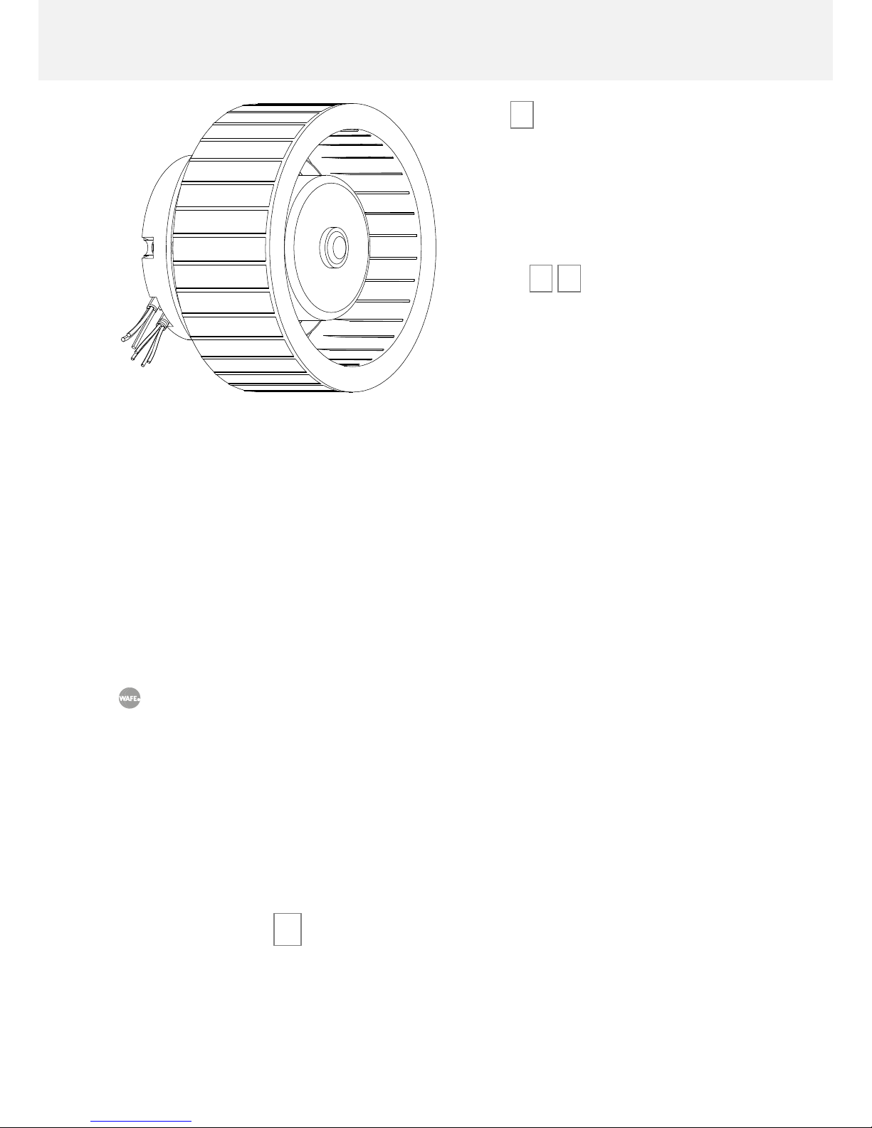
The unit is equipped with two electrically
powered radial fans with forward curved
blades and an integrated constant airflow
function. Even at high speeds or sudden
starts they remain quiet and reliable.
Filters 10 11
The production process of genuine WAFE
filters is fully automated: their cardboard
construction is cut by a German laser, synthetic filtration material is sliced at perfect
right angles by Swiss blades and each piece
is air-tightly isolated in the chamber vacuum sealer machine made in Italy.
End result is a precise product for the best
price on the market.
WAFE 350 filter portfolio currently contains
four models with different fineness of filtration: F7 and M5 (included) provide a high standard of air hygiene; F9 is suited for areas with
excessive levels of air pollution; and F7/AC composite filter with added active carbon particles
filters out various odours and volatile organic compounds (VOC) produced by plants and animals as well as from cleaners, wall paints, new furniture and some building materials.
In contrast with other ventilation units that ask for filter replacement in pre-set time
intervals (often too early or too late) WAFE 350 —thanks to its just-in-time technology— monitors the real state of filter clogging. We do so by examining the growing
pressure drop as detected by our pressure sensors and smart internal logic.
Earning money by selling you filters you don’t really need is not what we do.
The need for filter replacement is indicated by yellow glowing diode on the control panel of the
unit, digitally via e-mail or via personal notification on my.wafe.eu (if the unit is connected). For
more information, see WAFE 350 Maintenance / User maintenance / Replacing the filters.
Control panel 12
Pulling down the black decorative plate reveals a simple four-line, two colour LCD WAFE 350
control panel with two confirmation and two selection buttons and an information LED diode.
Nothing else is needed to control the basic functions of your unit - properly installed device
Figure 07: Powerful radial fan with
forward curved blades
propels the air inside
and outside of your
unit.
Page 16

16 | WAFE 350 Energy recovery ventilation
(see chapter WAFE 350 Installation) is capable of autonomous operation without any intervention from you.
For advanced feature control such as Intense ventilation (without previously installed
external button), Fireplace ventilation, Circulation and Night mode you need to log in
to my.wafe.eu (see WAFE 350 Operation / Unit control / Remote control via my.wafe.eu
web application).
The primary function of the panel is to provide a visual clue of your unit status. Blue glowing
diode tells you: "Do not worry. Just breathe. Live." Any different colour requires your attention.
See section WAFE 350 Operation / Unit control / Control via the LCD display.
Sensors 13 14 15
WAFE 350 is not only beautiful but smart and sensitive, too. Its complex logical operation is
supplied with data from seven temperature, humidity, pressure and CO2 sensors. Unit can then
analyse the quality of air flowing through it and in Intelligent mode (see section WAFE 350 Op-
eration / Operation modes) respond flexibly to any changes, increase ventilation intensity on the
fly or prevent potential damages.
Sheathing 16 17 18 19 20 21 22 23
Unit’s cover plates are made of powder coated aluminium sheet. The top sheet has two breakin inlets for additional external accessories.
Their clean, beautiful lines are the result of creative collaboration between WAFE designers
and engineers and the leading Czech design studio Anna Marešová Designers.
Anna holds several prestigious design awards in the field of product design: Czech
Grand Design Award (2012, second place), Dolce Vita Magazine/Prototype of the Year
(2011), National Student Design Award (2011, first place) and others. Her talent lends
WAFE 350 its industrial charm not often seen in devices to be installed in utility rooms.
Unit design, however, does not come at the expense of its practicality. The dominant black
decorative plate is harmonized by central LED diode; pull the plate down along the side rails
and you will reveal a simple control panel. Each cover plate (front, top, bottom and two lateral)
is simple to remove and allows easy access to the interior of the unit.
Page 17
WAFE 350 Installation | 17
WAFE 350 INSTALLATION
Information in the following chapter assume that your WAFE 350 unit will be installed
by certified WAFE service technician.
Any other form of installation without a previous agreement with WAFE s.r.o. may
affect the warranty on your device.
Planning the installation
Construction readiness
Purchase and delivery of WAFE 350 is preceded by consulting the parameters of the construction project with a responsible person.
In addition to the initial handover of the project parameters between two parties, make sure that at the time of installation the place of installation is prepared in accordance to the document Construction readiness: WAFE 350 En-
ergy recovery ventilation unit.
For the latest version of the document ask your WAFE sales representative or download it from www.wafe.eu/documents
Transportation and unpacking
When transporting the unit, be careful and bear in mind
the principles of working with heavy objects:
• Make sure that the transport path and the
place of rest are empty before transporting
the unit.
• Do not carry the unit over long distances
on your own without a proper transportation aid.
• While lifting the unit up bend your knees
and keep your back straight.
The unit has to be stored in a protective plastic cas-
ing and in the original box until the moment of instal-
lation.
Page 18

18 | WAFE 350 Installation
WAFE 350 package includes:
WAFE 350 energy recovery ventilation unit
M5 filter and F7 filter (inside the unit)
Wall rail
Cardboard stoppers for air pipes (4x)
230 V/50 Hz cable
User manual: WAFE 350 Energy recovery ventilation unit
Quick guide: WAFE 350 Energy recovery ventilation unit
Report any missing components to your supplier immediately.
Installation and handover
Installation starts with the arrival of WAFE service technician and ends when the unit is handed
over. The process consists of four steps requiring only minimum interaction from your side.
TECHNICIAN ACTION
USER ACTION
ASSEMBLY OF THE UNIT
ON THE WALL
Mounting the unit on the wall according
to the project and building readiness.
None.
SETTING UP THE UNIT
Turning the unit on, connecting it to PC
and setting it according to project parameters via WAFE Setup app.
None.
USER REGISTRATION
Creating a new user account and linking
it to the identification number of the
unit.
Filling required personal and contact
data into a digital form together with
WAFE service technician.
Advantages available for registered users only:
• Remote control via my.wafe.eu web application
• Access to mobile app
• Dynamic user statistics
• Automatic error message sending
• Unit software updates resulting in new features and more ef-
ficient operation
PŘEDÁNÍ JEDNOTKY
Final revision of the installation and filling the handover forms.
Signing the documents and taking the
unit over.
Table 03: Unit installation process by WAFE service technician .
Congratulations! Your WAFE 350 has been successfully installed.
Page 19

WAFE 350 Operation | 19
WAFE 350 OPERATION
WAFE 350 has been designed for your maximum comfort. After installation and initial setup of
operating values by WAFE technician (according to the construction project, see section
WAFE 350 Installation / Installation and handover), the unit needs little to no attention.
Operation modes
INTELLIGENT
MODE
The unit analyses its surroundings and through optimal ventilation keeps the CO2 levels as low
as possible.
Recommended for general use.
Requires manual activation and deactivation through my.wafe.eu.
In case CO2 sensors are damaged unit will automatically switch to the forced Weekly mode.
WEEKLY MODE
The unit provides ventilation according to its factory settings (constantly except for workdays
from 8AM till 4PM) or according to its own time schedule set up at my.wafe.eu.
Alternative to recommended general use.
Requires manual activation and deactivation through my.wafe.eu.
For other than default factory setting login to my.wafe.eu web application, activate the Weekly mode and
set your own time schedule. Remember to confirm the new setting!
HOLIDAY
[OUT]
Unit is in low power mode and ventilates the house once a day.
Suitable when leaving the ventilated areas for extended periods of time.
Requires manual activation and deactivation through my.wafe.eu.
SLEEP
[STAND-BY]
The unit is in low power mode, communicates over the internet (if connected) but does not
ventilate.
Turn on before unplugging from the power outlet.
Requires manual activation and deactivation through my.wafe.eu or via unit’s control panel.
Part of the transition to Sleep mode is a drying process: the unit closes its exterior flaps and the heat
exchanger and dries for 10 minutes. Unplugging the unit from the power outlet during this step might
result in residual moisture staying inside the unit.
OFF
The unit is unplugged from the power outlet: it does not ventilate and does not communicate
over the internet even if connected.
Not recommended: consider using the Sleep mode instead.
Switch the unit into Sleep mode (wait for the whole drying process to finish!) and unplug the cable.
ERROR
The unit does not ventilate and is awaiting the error resolution.
Automatically activated mode after encountering any errors.
After switching to Error mode, please, follow the steps in section WAFE 350 Maintenance / Problem solving.
Table 04: Operation modes of WAFE 350.
Page 20
20 | WAFE 350 Operation
Unit control
Control via LCD display
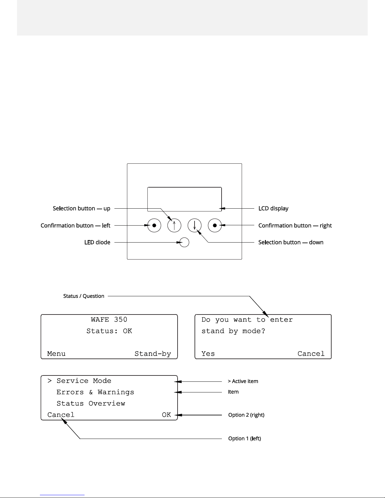
The unit’s control panel consists of an LCD display, four buttons with symbols and a LED diode.
Confirmation button—left/right (see Figure 08) are used to choose between Option 1 (Left)/2
(Right) (see Figure 09). Pressing the Confirmation button always activates the option on the
topmost line of unit display. To select a different option, scroll the menu by pressing Selection
button—up/down so that your desired option is displayed on the topmost line of unit display.
Figure 08: Buttons on the control panel .
Figure 09: The menu structure.
Page 21

WAFE 350 Operation | 21
Control panel LED diode has four light modes.
LED COLOUR
UNIT STATE
REQUESTED ACTION
Blue
Glowing
The unit is on. Everything is ok.
Breathe. Live.
Yellow
Glowing
The unit is on: incoming message.
Check the LCD display or my.wafe.eu
web application.
Red
Glowing
The unit is off: Error!
Check the LCD display or my.wafe.eu
web application and follow the instructions in section WAFE 350 Maintenance /
Problem solving.
Green
Flashing
The unit did not change its state;
green flashing light signal an ongoing
data transfer.
Nothing. Do not unplug the unit from
the power grid!
Table 05: LED light modes and related unit states.
Remote control via my.wafe.eu web application
Remote control of the unit is possible only if:
• The unit is connected to internet.
• You have been successfully registered as WAFE user and linked to your unit.
To control the unit remotely login to my.wafe.eu web application with your user identification
data.
Any command entered through my.wafe.eu might take up to one minute to reach the
unit.
First login to web application
After your user account registration, you’ll receive an activation email with your login details.
After you first log in and choose a new password the unit is ready for remote control via
my.wafe.eu web application.
Page 22

22 | WAFE 350 Operation
Special cases
Anti-freeze protection
Thanks to its unique flap system, WAFE 350 can operate down to -30 °C temperatures without
the need to pre-heat the incoming outside air. If the outside temperature goes below this level,
the fan turns off and the ventilation stops in order to protect the unit. The unit resumes its
operation once the temperature returns within the -30 to +45 °C limit.
Operation of the unit along with the fireplace
WAFE 350 energy recovery ventilation unit is pressure-neutral: the volume of fresh air brought
in is equal to the volume of waste air ejected from the building. In contrast, fireplace systems
are pressure-negative. To avoid the formation of negative pressure inside your home when
operating the unit along with the fireplace, the Fireplace ventilation function must be activated
during the whole time the fireplace is active. You can do so through my.wafe.eu web application (requires user registration, see WAFE 350 Installation / Installation and handover).
Do not forget to turn the function off once the fireplace is extinguished!
In case a heat or energy recovery ventilation unit like WAFE 350 is operated simultaneously
with the fireplace (stove, kiln, etc.), all applicable regulations and standards must be complied
with. Separate fresh air intake for the fireplace must be provided. We also recommend having
the ability to close the fireplace to minimise the possibility of negative pressure build up in the
combustion chamber or of fumes from the fireplace leaking into the interior.
Page 23

WAFE 350 Maintenance | 23
WAFE 350 MAINTENANCE
In order to provide your unit long and problem-free life, periodic maintenance by a WAFE service technician is necessary.
As a user you need to take care of only two regular maintenance procedures: exchanging the
filters and cleaning the façade outlets.
Maintenance by user
Replacing the filters
Newly purchased WAFE 350 comes with F7 filter (supply air) and M5 filter (exhaust air) already
preinstalled. Thanks to sensitive pressure sensors and internal logic your unit can accurately
detect the amount of clogging in each filter.
Blue glowing LED diode in the middle of the decorative plate 21 of the unit signals a
problem-free operation of the unit. That does include still having both filters clean.
Yellow glowing LED diode accompanied with a notification „Fresh/Exhaust filter is near
the end of a lifetime“ on the unit display or on my.wafe.eu signals that fresh (F7)/ex-
haust (M5) filter has exceeded a recommended degree of clogging. The unit remains
functional until the filter clogging reaches the critical level.
If you do not have a stock of replacement WAFE filters, contact us promptly at
www.wafe.eu/filters or call +420 273 139 700. Make sure to use high-quality WAFE filters only.
Original filters can be identified by a WAFE logo.
Red glowing LED light accompanied with an error message „Fresh/Exhaust filter lifetime
ended. Please, replace now!“ on the unit display or at my.wafe.eu signals completely
clogged fresh F7/exhaust M5 filter. The unit switches into Error mode and will not
operate until the filters are replaced.
Replacing the filters is necessary in two cases, whichever comes first:
• 12 months have passed since the last filter replacement.
• The unit has switched to an Error mode (identifiable by the glowing red LED diode and an
error message on the unit display).
The unit cannot operate without filters.
Page 24
24 | WAFE 350 Maintenance
Filter replacement procedure
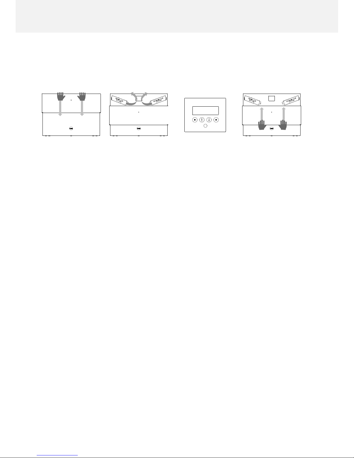
Before starting the filter replacement procedure make sure the unit is in Filter replacement mode. You can activate it only via unit display by selecting and confirming the
appropriate option
01 Press the decorative
cover downwards with both
hands until it reaches its
lower end position and
check the message on the
display. Follow the instructions on the screen.
02 Pull the corresponding
filter stopper out of the unit
body as shown in the picture
above. Pull out the old filter
by its strap and insert a new
one. Mind the correct position of the insertion according to the instructions on the
filter. Return the stopper as
far to the back as it fits.
03 Confirm the comple-
tion of the replacement
procedure on the display
keyboard as instructed. The
unit will resume its operation.
04 Use both hands to
push the decorative cover
upwards. The cover will automatically move into its upper end position.
Cleaning the air diffusers
Air diffusers optimise the direction and flow of intake and exhaust air. For better air permeability, it is required to provide periodic cleaning of both interior and exterior air diffusers at
least once per 6 months. To do so wipe the edges and insides of the diffusers and remove any
sediment dirt with a dry cloth. Avoid using water and chemicals unless absolutely necessary.
Problem solving
In case of an error contact WAFE customer service immediately at +420 273 139 700.
For easier problem identification, note the error code number (displayed on the unit display)
and the type of your unit (see the nameplate on the side of the unit).
While the unit is not operating due to the error, your home is left without ventilation. This
results in the reduction of indoor air quality and can lead to increased humidity or moulding.
Avoid prolonged shutdowns of your ventilation system.
During shorter periods of absence, it is appropriate to leave the unit in Intelligent
mode. During longer breaks leave the unit in Holiday mode [Out].
Page 25

Warranty and responsibility | 25
WARRANTY AND RESPONSIBILITY
Warranty
The warranty does not cover the damage of the unit or its individual components caused by:
• improper handling or storage,
• non-compliance with the instructions provided in the manual,
• incorrect assembly not provided by the manufacturer,
• arbitrary tampering and misuse
• neglecting the prescribed mandatory maintenance (such as a failure to replace clogged fil-
ters, etc.),
• use or installation of parts that have not been approved in writing by the manufacturer (e.g.
operating the unit using non-original WAFE filters),
• non-compliance with the requirements for connected devices supplied by a third party (pro-
tection, security, etc.),
• violent damage, natural disaster or extreme operating conditions and influences, the effects
of electromagnetic interference, etc.
The warranty also does not cover normal wear and tear.
Responsibility
WAFE 350 energy recovery ventilation unit has been developed and manufactured for use in
ventilation systems for residential applications. Any other way of installation and operation
than the one approved by the manufacturer is considered inappropriate and can cause damage to the unit or property or personal injury for which the manufacturer cannot be held responsible.
The manufacturer shall not be held responsible or liable for damages caused by:
• non-compliance with a proper installation and safety instructions stated in this manual and
applicable regulations,
• failure to follow the instructions for operation, service and maintenance,
• the use of spare parts and accessories not supplied or prescribed by the manufacturer,
• improper, incompetent or incorrect installation,
• pollution of the system,
• normal wear and tear,
• expiration of the warranty period.
Page 26

26 | Notes
NOTES
Page 27

Notes | 27
Page 28

28 | Notes
Page 29

Notes | 29
Page 30
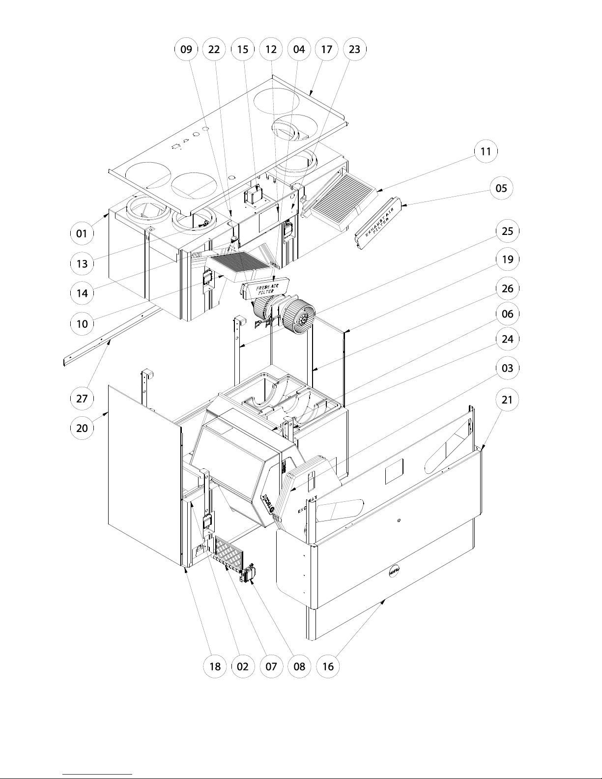
Exploded-view drawing of WAFE 350
For m ore information and full components list go to p. 12–13.
Page 31

Page 32

USER MANUAL: WAFE 350 ENERGY RECOVERY VENTILATION UNIT
v1.0
WAFE s.r.o. Kolbenova 931/40b, 19000 Prague 9 – Vysočany
e-mail: [email protected], phone: +420 273 139 700, web: www.wafe.eu
 Loading...