

Page 1
USER MANUAL
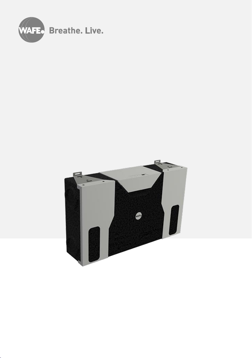
WAFE 200 E Energy Recovery Ventilation Unit
v1.0
Page 2

Page 3

About the document I 3
Table od contens
About the document 3
Safety instruction 5
Disposal 5
Installation 6
Planning the installation 6
Eletrical installation 7
External controller 9
Controller functions 10
Operation and Maintenance Indication 11
External control signal 0-10V 11
Boost function with an external switch 12
User maintenance 12
Warranty and responsibility 13
Warranty 13
Responsibility 13
Notes 14
ABOUT THE
DOCUMENT
Information stated in the
User manual:
WAFE 200 E Energy recovery ventilation
unit
(hereinafter “manual”) are to pro-
vide safe and economically efficient operation of WAFE 200 E energy recovery
ventilation unit (hereinafter “unit”).
Read carefully, please.
Manual and its contents are owned by
WAFE s.r.o. For either partial or full publication, a written approval from
WAFE s.r.o. is necessary. Reproduction
for review purposes is allowed and there
is no need for official approval.
Manual is written, published and applicable exclusively for WAFE 200 E unit.
Original version of this document was
created in Czech language. The producer is not responsible for any possible
discrepancies due to the translation.
As we are constantly upgrading and improving our devices, your version of the
unit might look different than the one
portraited in this manual.
© WAFE 2018. All rights reserved.
Page 4
4 I About the document
Type designation
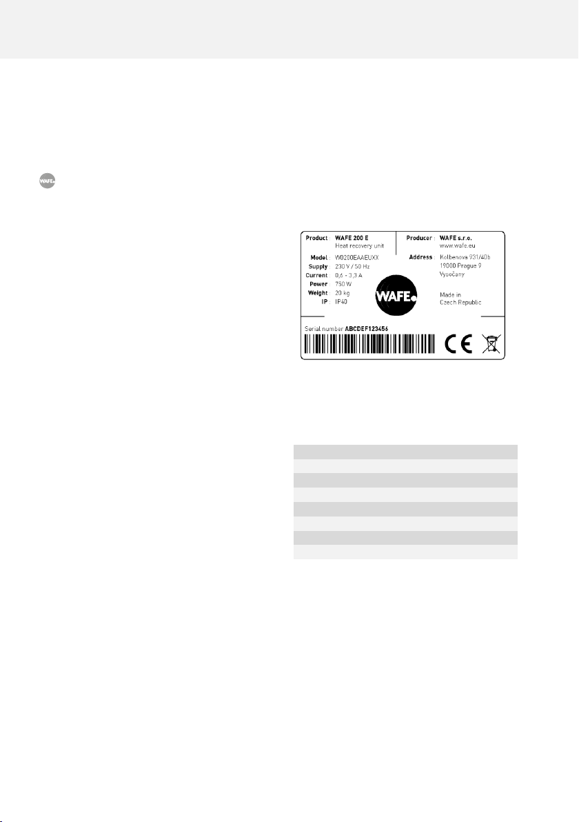
Nameplate is used to identify the precise
model of the unit which is necessary for the
safe use of the product. The nameplate is
permanently located on the side of the unit.
Figure 01: An example of a unit
nameplate.
Manufacturer
W
Capacity
0200
Version C Recovery ventilation system
E
Versions of the electronics
A
Region
EU
Sheating
A
Preheating
N
Table 01: A structure of unit part
number.
Symbols used
Important information.
Unique feature differentiating your
unit from the competition.
There is a danger of unit or ventilation system damage.
There is a danger of personal injury.
Intended use
WAFE 200 E energy recovery ventilation unit
is an air ventilation device with an active
heat and humidity recovery function designed for comfortable and ecological ventilation management.
The unit can be used only for the purposes
for which it was developed and manufactured and for which it is technically eligible
in accordance with the conditions specified
by the manufacturer. Its design, implementation and technical condition adhere to
general safety requirements.
Page 5

Safety instruction I 5
SAFETY INSTRUCTION
Before using the ventilation unit carefully read all the safety instructions below. By
compliance with the following, chances of mechanical or bodily damage are mini-mised. Manufacturer is not responsible for any damages resulting from non-compliance
with these instructions.
• Ventilation unit must be installed in accordance with the general safety regulations valid
in the place of installation.
• Ventilation unit must be installed, connected, operated and serviced only by a properly
trained service technician, that is, a person with appropriate education, experience and
knowledge of all the relevant regulations, standards and potential risks and dangers involved.
• When laying the wires connected to the unit it is necessary to make sure they are not
exposed to any mechanical damage or detrimental environmental effects and that they
do not interfere with the use of the space in which the unit is installed.
• In case of damaged power supply, it must be replaced by manufacturer, his service tech-
nician or equally qualified person.
• To prevent damage and injury when manipulating with the electrical plug, pull the plug
head itself instead of its cable.
• The unit cannot be used by children under 8 years old and persons with reduced physical,
sensory or mental capabilities or lack of experience and knowledge, unless they are supervised or instructed on the use of the unit in a safe way and understand the potential
dangers.
• Children must not play with the unit or perform the cleaning and maintenance of it.
Disposal
Dispose the package material in an environmentally friendly way. Once the life cycle of
WAFE 200 E comes to its end choose an eco-friendly option for its disposal. The unit must not
be disposed together with a regular household waste. The unit has been classi-fied according
to the EU Directive 2012/19/EU. The directive is valid throughout Europe and it sets a framework for returning and recycling procedures of disposed appliances..
Page 6
6 I Installation
WAFE 200 E INSTALLATION
Information in the following chapter assume that your WAFE 200 E unit will be installed
by certified WAFE service technician.
Any other form of installation without a previous agreement with WAFE s.r.o. may affect
the warranty on your device.
Planning the installation
Construction readiness
Purchase and delivery of WAFE 200 E is preceded by consulting the parameters of the construction
project with a responsible person.
Transportation and unpacking
When transporting the unit, be careful and bear in mind the principles of working with
heavy objects:
• Make sure that the transport path and the place of rest are empty before
transporting the unit.
• Do not carry the unit over long distances on your own without a
proper transportation aid.
• While lifting the unit up bend your knees and keep your back
straight.
The unit has to be stored in a protective plastic casing
and in the original box until the moment of installation.
Page 7
Installation I 7
ELECTRICAL INSTALLATION
Electrical installation must be done in accordance with applicable law and regulations by
qualified and authorized personnel.
Electricity is supplied to the unit through a power cable with a standard EU plug for 230V. The
connecting cable for the external control and the preheater is to be connected directly to the central control board. The cover board is attached with four screws. Release the four screws and lead
the cables of external activators through cable grommets (holes) that may be broken out accordingly.
Attachment of the adapter board
The external controller may be mounted on a standard switch box. 8-pole terminal block of the
external controller is connected to a 4-pole terminal block X0 of the central control board with a 4
venous shielded cable (type J-Y(ST)Y 2x2x0,6).
Control board connecting terminal X0
Contact labeling
X0 01
+12V
X0 02
Us (intake ventilator control voltage)
X0 03
Ue (outtake ventilator control voltage)
X0 04
GND
Table 02: Terminal block for X0 connection of the control board.
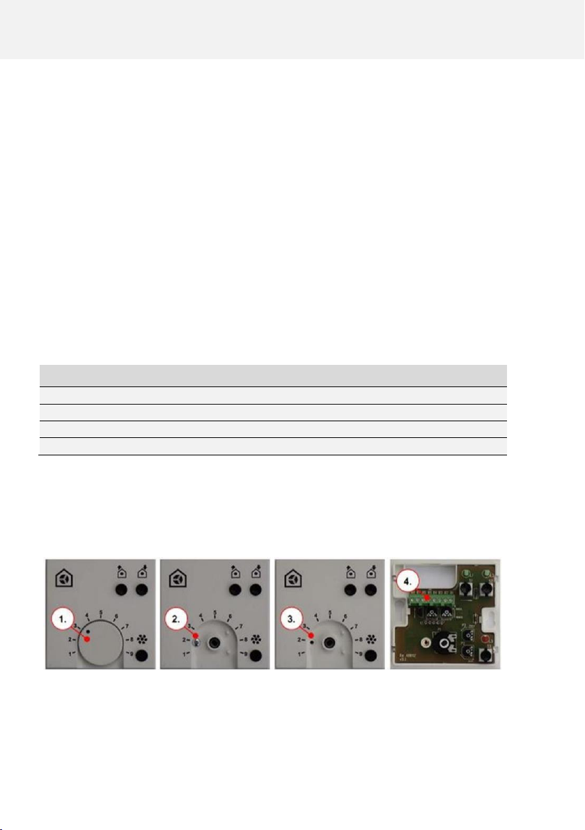
1. Push out rotary
button
2. Release screw
3. Take of top cover
4. Clamps for external
controller
Figure 02: External controller.
Page 8
8 I Installation
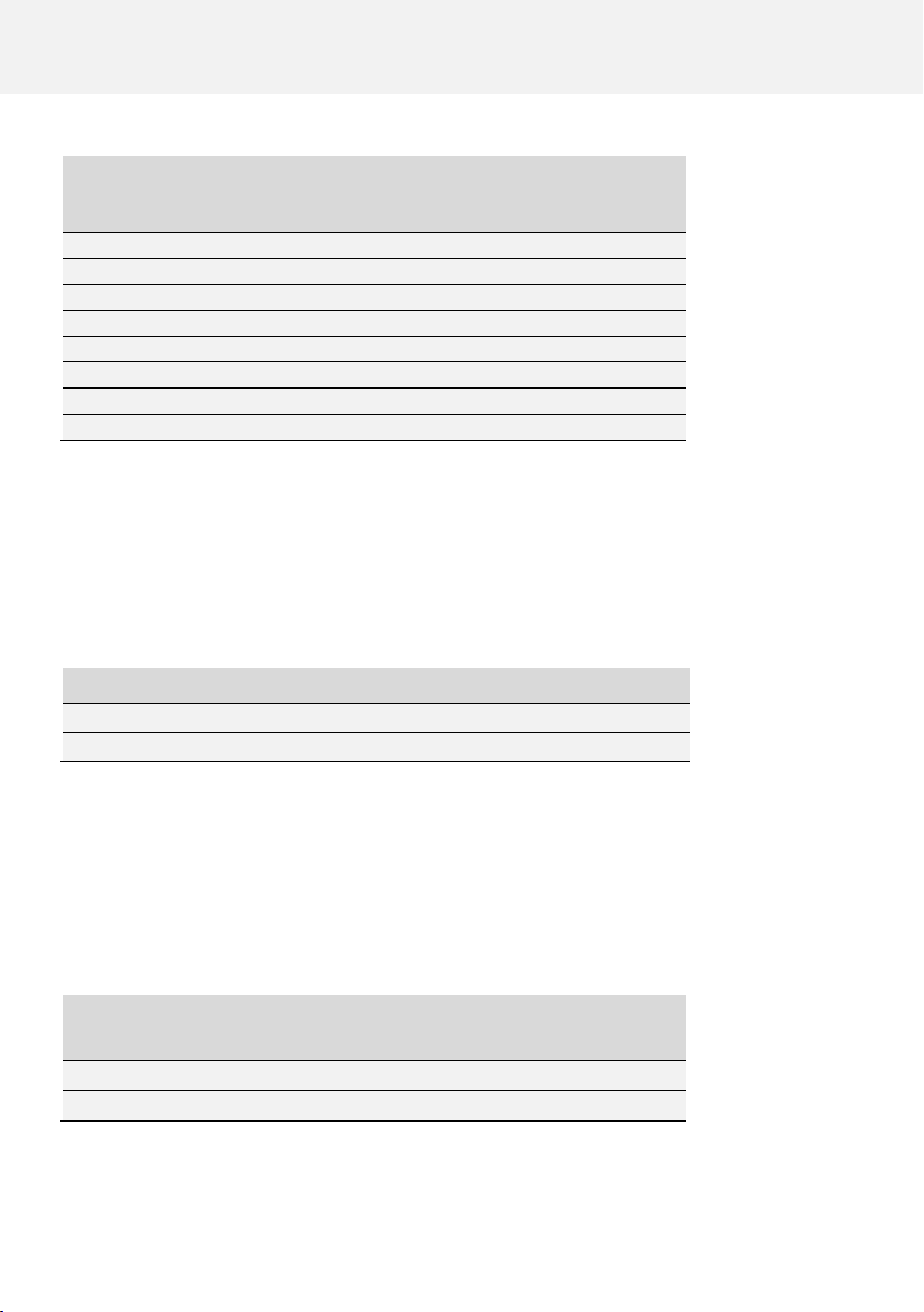
Connecting clamp of the
external controller
Contact labels
X 01
+12V
X 02
Us (intake ventilator control voltage)
X 03
Ue (outtake ventilator control voltage)
X 04
GND
X 05
Analog input 0-10V
X 06
Analog input GND
X 07
Boost input
X 08
Boost input GND
Table 03: Terminal block for external controller connection.
External boost switch connection
Boost may be activated by one or more switches in parallel connection. Potential-free con-nection
between the sensor and the external controller clamp needs to be realized through at least two
conductors (recommended cable J-Y(ST)Y 2x2x0.6).
Connecting clamp for Boost
Contacts for Boost
X 07
Cable 1
X 08
Cable 2 GND
Table 04: Terminal block for boost connection.
External sensor connection
Provoz v módu Automatic Sensor (automaticky podle čidla) je řízen pomocí analogového signálu
0-10V, který je generován jedním nebo více čidly. Propojení mezi čidly a hlavní řídící jednotkou je
zajištěno kabelem, který vede od čidla do svorky externího ovladače.
Připojovací svorka
pro externí sensory
Kontakty externích sensorů
X 05
Cable 1 (0-10 V)
X 06
Cable 2 GND
Table 05: Terminal block for external sensor connection.
Page 9
Controller I 9
EXTERNAL CONTROLLER
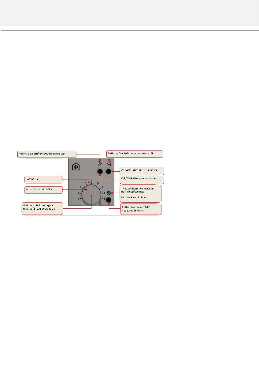
External controller uses a rotary button with a scale up to nine to control the level of ventilation.
Two ON/OFF buttons allow for the required activity set up. The ON status is indicated by green
LED light.
1. Both ON – Regular Mode (both ventilators active)
2. Outtake ON only – Only outtake active
3. Intake ON only – Only intake active
Boost button for Boost mode.
Filter reset button after filter exchange.
Red LED symbol to signalize actual operation mode.
Figure 03: Button and light overview on the external controller.
Page 10
10 I Controller
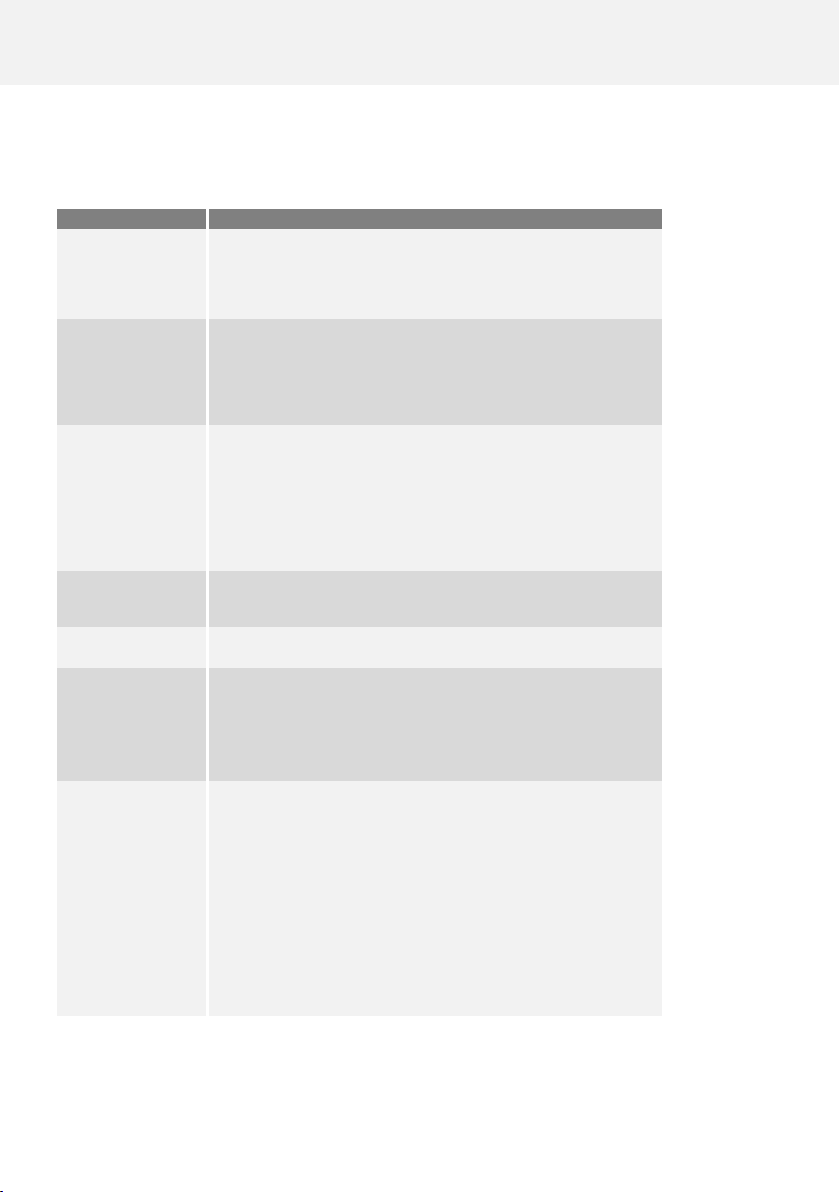
Controller functions
Status
Function
Setting Position
Absence Mode
Position 1: 1 min ON 6 min OFF
Position 3: 6 min ON 1 min OFF
Position of the rotary button between 1 and 3: relatively divided ON and OFF
Rotary Button
Operation Mode
Position 4: lowest airflow
Position 9: highest airflow
Position of rotary button between 4 and 9: gradual increase/decrease of airflow
Air Outtake Button
Press the button and set up the airflow to turn on outtake mode. Press the
button again to turn off.
Do not use this button in combination with fireplace mode unless intake
button is on as well. Heat recovery ventilation and fire in the fireplace is
not recommended due to risk of vacuum and harmful substance air contamination.
Air Intake Button
Press the button and set up the airflow to turn on intake mode. Press the button again to turn off.
Regular Mode
Press both Intake and Outtake button to turn on Regular Mode.
Boost Mode Button
Press Boost mode button to turn on Boost. The unit will ventilate at maximum
(9) level for 15 minutes.
After 15 minutes of Boost mode, the ventilators will return to original air flow
level. Press the button for more than 3 seconds to turn off Boost manually.
Filter Exchange Reset
Status
For regular filter status check, a time meter for 180 days is set up in the unit
control board.
Push the Filter Reset Button for more than 3 seconds to reset the time meter
to zero.
If the reset is done within the 180day period, the LED light will blink 4 times.
Do not use the reset button during Boost mode.
Function
Table 06: Operation functions of the external controller.
Page 11
Controller I 11
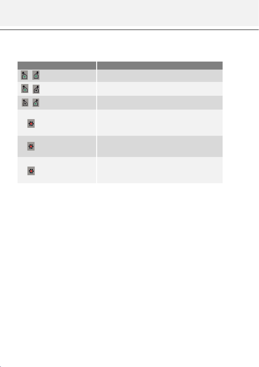
Operation and Maintenance Indication
Table 07: Operation and maintenance indication.
External control signal 0-10V
The unit can be controlled with and external 0-10V signal that governs the speed of ventilators and
so reduces or increases the air flow. The external signal overrides the rotary button.
To allow for external 0-10V signal control, set the rotary button to level 1.
Symbol
LED signaling
Function/Interpretaion/Measure
Both LED lights green
Start balanced pressure ventilation by pressing both A and B buttons.
Outtake LED green
Start Outtake mode by pressing A button only. Intake ventilator stays
off.
Intake LED Green
Start Intake mode by pressing B button only. Outtake ventilator stays
off.
Ventilation LED red
Start Boost for 15 minutes by pressing Boost button. Both ventilators
go up to maximum speed (9).
Boost mode may be activated during any operation Mode.
Ventilation LED red blinking
Absence Mode active.
Absence mode may be activated during any operation Mode.
Ventilation LED red rapid
blinking
The timer for filters indicates for an exchange. Please check the filter
status and reset.
Please do net reset the filter exchange timer during Boost mode.
Page 12

12 I Maintenance
Boost function with an external switch
External switches for boost ventilation are placed mostly in rooms, from which you need to get rid
of waste air more rapidly, such as bathrooms, toilets, kitchen, etc. The switch activates maximal
ventilation power of the unit to release air contaminated by odors or vapor.
Functions and visualizations for boost ventilation are described in the external setup panel settings. Boost will be activated by pressing the connected switch, which will interrupt the ongoing
mode for 15 minutes (factory setting). After the boost period is over, the unit will switch back to
the previously set up mode.
USER MAINTENANCE
User maintenance comprises of periodical filter exchange and cleaning of intake and outtake air
vents. It is recommended to exchange filters every three months, six months the latest.
During the exchange it is recommended to check the state of all other filters of the heat recovery
system and make an exchange if necessary.
In case proper maintenance is not carried out regularly, the air quality of the interior may
be reduced and the electrical consumption of the unit may rise!
Filter exchange
The device must not be operated without filters. During the exchange or maintenance,
the unit must be switched off!
There are two high quality filters placed inside the ventilation unit. You will recognize the ba the
WAFE logo. The filters may be purchased through on order at [email protected]. These two filters need
to be checked if notified on the control panel. Please follow these steps:
1. Detach the unit from electricity
2. Take out the opening seal by the strap
3. Take out the filter by its strap
4. Place the new filter inside with the arrow pointing towards the center of the unit
5. Plug the seal back in
6. Connect the unit to electricity
Page 13

Poznámky I 13
WARRANTY AND RESPONSIBILITY
Warranty
The warranty does not cover the damage of the unit or its individual components caused by:
• improper handling or storage,
• non-compliance with the instructions provided in the manual,
• incorrect assembly not provided by the manufacturer,
• arbitrary tampering and misuse,
• neglecting the prescribed mandatory maintenance (such as a failure to replace clogged filters,
etc.),
• use or installation of parts that have not been approved in writing by the manufacturer (e.g.
operating the unit using non-original WAFE filters),
• non-compliance with the requirements for connected devices supplied by a third party (protec-
tion, security, etc.),
• violent damage, natural disaster or extreme operating conditions and influences, the effects of
electromagnetic interference, etc.
The warranty also does not cover normal wear and tear.
Responsibility
WAFE 200 E energy recovery ventilation unit has been developed and manufactured for use in ven-
tilation systems for residential applications. Any other way of installation and operation than the
one approved by the manufacturer is considered inappropriate and can cause damage to the unit
or property or personal injury for which the manufacturer cannot be held responsible.
The manufacturer shall not be held responsible or liable for damages caused by:
• non-compliance with a proper installation and safety instructions stated in this manual and ap-
plicable regulations,
• failure to follow the instructions for operation, service and maintenance,
• the use of spare parts and accessories not supplied or prescribed by the manufacturer,
• improper, incompetent or incorrect installation,
• pollution of the system,
• normal wear and tear,
• expiration of the warranty period.
Page 14
14 I Notes
NOTES
Page 15
Poznámky I 15
Page 16
16 I Notes
Page 17

Page 18

UŽIVATELSKÝ MANUÁL: REKUPERAČNÍ JEDNOTKA WAFE 200 E
v1.0
WAFE s.r.o. Kolbenova 931/40b, 19000 Praha 9 – Vysočany
e-mail: [email protected], tel.: +420 273 139 700, web: www.wafe.eu
 Loading...