

Waeco SinePower MSI912, SinePower MSI924, SinePower MSI1312, SinePower MSI1324, SinePower MSI1812 Installation and Operating Manual [ml]
...Page 1
BREAKER
SinePower MSI912, MSI924, MSI1312,
MSI1324, MSI1812, MSI1824,
MSI1812T, MSI1824T
DE 9 Sinus Wechselrichter
Montage- und Bedienungsanleitung
EN 36 Sine wave inverter
Installation and Operating Manual
FR 62 Onduleur sinusoïdal
Instructions de montage et de service
ES 89 Convertidor de ondas seno
Instrucciones de montaje y de uso
IT 116 Inverter sinusoidale
Istruzioni di montaggio e d’uso
NL 143 Sinus ondulator
Montagehandleiding en gebruiksaanwijzing
DA 170 Sinus ensretter
Monterings- og betjeningsvejledning
SV 196 Sinus växelriktare
Monterings- och bruksanvisning
NO 221 Sinus vekselretter
Monterings- og bruksanvisning
FI 247 Sinus -vaihtosuuntaaja
Asennus- ja käyttöohje
PT 273 Conversor sinusoidal
Instruções de montagem e manual de
instruções
RU 300 Синусоидальный инвертор
Инструкция по монтажу и
эксплуатации
PL 328 Przetwornica sinusoidalna
Instrukcja montażu i obsługi
CS 355 Sinusový měnič
Návod k montáži a obsluze
Page 2

Fordern Sie weitere Informationen zur umfangreichen Produktpalette aus dem Hause
DE
EN
FR
ESITNL
DASVNOFIPTRUPL
CS
Dometic WAECO an. Bestellen Sie einfach unsere Kataloge kostenlos und
unverbindlich unter der Internetadresse: www.dometic-waeco.de
We will be happy to provide you with further information about Dometic WAECO
products. Please order our free catalogue with no obligation to buy on our homepage:
www.dometic-waeco.com
Demandez d’autres informations relatives à la large gamme de produits de la maison
Dometic WAECO. Commandez tout simplement notre catalogue gratuitement et sans
engagement à l’adresse internet suivante : www.dometic-waeco.com
Solicite más información sobre la amplia gama de productos de la empresa Dometic
WAECO. Solicite simplemente nuestros catálogos de forma gratuita y sin compromiso
en la dirección de Internet: www.dometic-waeco.com
Per ottenere maggiori informazioni sull’ampia gamma di prodotti Dometic WAECO è
possibile ordinare una copia gratuita e non vincolante del nostro Catalogo all’indirizzo
Internet: www.dometic-waeco.com
Maak kennis met het omvangrijke productscala van de firma Dometic WAECO. Bestel
onze catalogus gratis en vrijblijvend onder het internetadres:
www.dometic-waeco.com
Bestil yderligere information om det omfattende produktudvalg fra Dometic WAECO.
Bestil vores katalog gratis og uforpligtende på internetadressen:
www.dometic-waeco.com
Inhämta mer information om den omfattande produktpaletten från Dometic WAECO:
Beställ våra kataloger gratis och utan förpliktelser under vår Internetadress:
www.dometic-waeco.com
Be om mer informasjon om det rikholdige produktutvalget fra Dometic WAECO. Bestill
vår katalog gratis uforbindtlig på Internettadressen: www.dometic-waeco.com
Pyytäkää lisää tietoja Dometic WAECOn kattavista tuotevalikoimista. Tilatkaa
tuotekuvastomme maksutta ja sitoumuksetta internet-osoitteesta:
www.dometic-waeco.com
Peça mais informação sobre a ampla gama de produtos da empresa Dometic
WAECO. Peça simplesmente os nossos catálogos de forma gratuita e sem qualquer
compromisso, disponível no site: www.dometic-waeco.com
Запросите дальнейшую информацию об обширном ассортименте продукции
компании Dometic WAECO. Просто закажите наши каталоги на сайте
www.dometic-waeco.com; эта услуга предоставляется бесплатно и ни к чему не
обязывает.
Proszę się zapoznać z informacjami na temat szerokiej gamy produktów Dometic
WAECO. Proszę zamówić nasz bezpłatny katalog i zapoznać się zniewiążącą ofertą
pod adresem: www.dometic-waeco.com
Žádejte další informace o rozsáhlé nabídce výrobků firmy Dometic WAECO. Stač
zdarma a nezávazně objednat naše katalogy na internetové adrese:
www.dometic-waeco.com
í
Page 3
SinePower
1
1
2
3
1
BREAKER
3
2
25 cm
B
R
E
A
K
E
R
25 cm
3
Page 4
4
INPUT
BREAKER
AB
NEG (-)
REMOTE
CHASSIS
DC INPUT
GROUND
B
A
1
POS (+)
1
A
B
ENB
N.O.
ENB
COM
GND
N.C.
2
xxx
x
345
5
1
2
4 3
5
6
OUTPUT
SinePower
AC
AC
MSI900, MSI1300,
MSI1800
AC OUTPUT
OUT
VOLT.
12345678
5
4
FREQ.
LOAD
STATUS
POWER
SAVING
ON
OFF
REMOTE
N.A.
OPTION
1
0
1
2
3
4
Page 5
SinePower
ON
OUT
VOLT.
FREQ.
POWER
SAVING
N.A.
OPTION
1
0
12345678
OFF
REMOTE
LOAD
STATUS
AC OUTPUTAC INPUT
BREAKER
67
1
3
4
MSI1800T
5
2
8
7
1
4
2
3
8
5
Page 6
SinePower
Input
230 V AC
Output
230 V AC
N
MSI
DC
Input
DC
230 V AC
FI 2
RCD
FI 1
RCD
PE
L1
N
PE
L1
N
PE
L!
N
PE
L1
654
1
3
7
2
9
6
Page 7
SinePower
ENB
GND
OFF
ON
OFF:INV.
ON:INV.
0
OFF
ON
LOW:INV.
HI:INV.
GND
ENB
(TR ON)
(TR OFF)
TR
a
ENB
BAT+
BAT–
OFF
ON
OFF:INV.
ON:INV.
b
DC POWER
GND
ENB
+
–
OFF
ON
OFF:INV.
ON:INV.
c
7
Page 8
NEG (-)
REMOTE
CHASSIS
DC INPUT
GROUND
B
A
1
POS (+)
1
A
B
ENB
N.O.
ENB
COM
GND
N.C.
2
xxx
x
345
ON
OUT
VOLT.
FREQ.
POWER
SAVING
N.A.
OPTION
1
0
12345678
OFF
REMOTE
LOAD
STATUS
AC OUTPUTAC INPUT
BREAKER
ON
OUT
VOLT.
FREQ.
POWER
SAVING
N.A.
OPTION
1
0
12345678
OFF
REMOTE
LOAD
STATUS
AC OUTPUT
MSI900, MSI1300,
MSI1800
MSI1800T
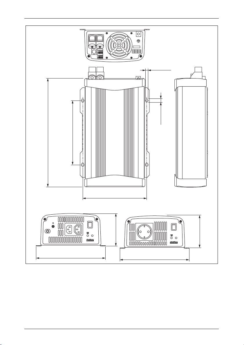
186,6 mm
200,6 mm
10 mm
Ø7 mm
MSI900: 186,5 mm
MSI1300: 220 mm
MSI1800: 245 mm
MSI1800T: 284 mm
MSI900: 313 mm, MSI1300: 342 mm
MSI1800: 367 mm, MSI1800T: 406 mm
94,5 mm
200,6 mm
94,5 mm
d
SinePower
8
Page 9

DE
SinePower
Bitte lesen Sie diese Anleitung vor Einbau und Inbetriebnahme sorgfältig durch und bewahren Sie sie auf. Geben Sie sie im Falle einer
Weitergabe des Produktes an den Nutzer weiter.
Inhaltsverzeichnis
1 Erklärung der Symbole . . . . . . . . . . . . . . . . . . . . . . . . . . . . . . . . . . 10
2 Allgemeine Sicherheitshinweise . . . . . . . . . . . . . . . . . . . . . . . . . . . 10
3 Lieferumfang . . . . . . . . . . . . . . . . . . . . . . . . . . . . . . . . . . . . . . . . . . 13
4 Zubehör . . . . . . . . . . . . . . . . . . . . . . . . . . . . . . . . . . . . . . . . . . . . . . 13
5 Zielgruppe dieser Anleitung . . . . . . . . . . . . . . . . . . . . . . . . . . . . . . . 13
6 Bestimmungsgemäßer Gebrauch . . . . . . . . . . . . . . . . . . . . . . . . . . 14
7 Technische Beschreibung . . . . . . . . . . . . . . . . . . . . . . . . . . . . . . . . 15
8 Wechselrichter montieren . . . . . . . . . . . . . . . . . . . . . . . . . . . . . . . . 19
9 Wechselrichter anschließen. . . . . . . . . . . . . . . . . . . . . . . . . . . . . . . 20
10 Wechselrichter benutzen . . . . . . . . . . . . . . . . . . . . . . . . . . . . . . . . . 26
11 Wechselrichter pflegen und reinigen . . . . . . . . . . . . . . . . . . . . . . . . 29
12 Fehlerbeseitigung . . . . . . . . . . . . . . . . . . . . . . . . . . . . . . . . . . . . . . 30
13 Gewährleistung . . . . . . . . . . . . . . . . . . . . . . . . . . . . . . . . . . . . . . . . 31
14 Entsorgung. . . . . . . . . . . . . . . . . . . . . . . . . . . . . . . . . . . . . . . . . . . . 31
15 Technische Daten . . . . . . . . . . . . . . . . . . . . . . . . . . . . . . . . . . . . . . 32
9
Page 10

DE
Erklärung der Symbole SinePower
1 Erklärung der Symbole
WARNUNG!
!
A
I
➤ Handlung: Dieses Symbol zeigt Ihnen, dass Sie etwas tun müssen. Die
erforderlichen Handlungen werden Schritt für Schritt beschrieben.
✓ Dieses Symbol beschreibt das Ergebnis einer Handlung.
Abb. 1 5, Seite 3: Diese Angabe weist Sie auf ein Element in einer Abbildung hin, in diesem Beispiel auf „Position 5 in Abbildung 1 auf Seite 3“.
Sicherheitshinweis: Nichtbeachtung kann zu Tod oder schwerer
Verletzung führen.
ACHTUNG!
Nichtbeachtung kann zu Materialschäden führen und die
Funktion des Produktes beeinträchtigen.
HINWEIS
Ergänzende Informationen zur Bedienung des Produktes.
2 Allgemeine Sicherheitshinweise
2.1 Allgemeine Sicherheit
Der Hersteller übernimmt in folgenden Fällen keine Haftung für Schäden:
Montage- oder Anschlussfehler
Beschädigungen am Produkt durch mechanische Einflüsse und Über-
spannungen
Veränderungen am Produkt ohne ausdrückliche Genehmigung vom
Hersteller
Verwendung für andere als die in der Anleitung beschriebenen Zwecke
10
Page 11

DE
SinePower Allgemeine Sicherheitshinweise
WARNUNG!
!
Benutzen Sie das Gerät nur zu seinem bestimmungsgemäßen
Gebrauch.
Betreiben Sie das Gerät nicht in feuchter oder nasser Umge-
bung.
Betreiben Sie das Gerät nicht in der Nähe brennbarer Materia-
lien.
Betreiben Sie das Gerät nicht in explosionsgefährdeten Berei-
chen.
Die Wartung und Reparatur darf nur durch eine Fachkraft ge-
schehen, die mit den damit verbundenen Gefahren bzw. einschlägigen Vorschriften vertraut ist.
Personen (einschließlich Kinder), die aufgrund ihrer physi-
schen, sensorischen oder geistigen Fähigkeiten oder ihrer Unerfahrenheit oder Unkenntnis nicht in der Lage sind, das
Produkt sicher zu benutzen, sollten dieses Produkt nicht ohne
Aufsicht oder Anweisung durch eine verantwortliche Person
nutzen.
Elektrogeräte sind kein Kinderspielzeug!
Verwahren und benutzen Sie das Gerät außerhalb der Reichweite von Kindern.
2.2 Sicherheit bei der Installation des Gerätes
WARNUNG!
!
A
Die Installation des Gerätes darf ausschließlich von entspre-
chend ausgebildeten Fachbetrieben durchgeführt werden, die
mit den anzuwendenden Richtlinien und Sicherheitsvorkehrungen vertraut sind.
Bei falscher Installation elektrischer Geräte auf Booten kann es
zu Korrosionsschäden am Boot kommen. Die Installation des
Gerätes sollte von einem fachkundigen (Boots-)Elektriker
durchgeführt werden.
ACHTUNG!
Achten Sie auf einen sicheren Stand!
Das Gerät muss so sicher aufgestellt und befestigt werden,
dass es nicht umstürzen oder herabfallen kann.
11
Page 12

DE
Allgemeine Sicherheitshinweise SinePower
Setzen Sie das Gerät keiner Wärmequelle (Sonneneinstrah-
lung, Heizung usw.) aus. Vermeiden Sie so zusätzliche
Erwärmung des Gerätes.
Müssen Leitungen durch Blechwände oder andere scharf-
kantige Wände geführt werden, benutzen Sie Leerrohre bzw.
Leitungsdurchführungen.
Verlegen Sie Leitungen nicht lose oder scharf abgeknickt an
elektrisch leitenden Materialien (Metall).
Ziehen Sie nicht an Leitungen.
Verlegen Sie 230-V-Netzleitung und 12/24-V-Gleichstrom-
leitung nicht zusammen im gleichen Leitungskanal (Leerrohr).
Befestigen Sie die Leitungen gut.
Verlegen Sie die Leitungen so, dass keine Stolpergefahr ent-
steht und eine Beschädigung des Kabels ausgeschlossen ist.
2.3 Sicherheit beim Betrieb des Gerätes
WARNUNG!
!
Betreiben Sie das Gerät nur, wenn das Gehäuse und die
Leitungen unbeschädigt sind.
Auch nach Auslösen der Schutzeinrichtung (Sicherung) bleiben
Teile des Wechselrichters unter Spannung.
Unterbrechen Sie bei Arbeiten am Gerät immer die Strom-
versorgung.
A
12
ACHTUNG!
Achten Sie darauf, dass Luftein- und ausgänge des Geräts nicht
verdeckt werden.
Achten Sie auf gute Belüftung. Der Wechselrichter produziert
Verlustwärme, die abgeführt werden muss.
Verbinden Sie den 230-V-Ausgang des Wechselrichters
(Abb. 6 5, Seite 4 und Abb. 7 5, Seite 5) nicht mit einer anderen 230-V-Quelle.
Page 13

DE
SinePower Lieferumfang
3Lieferumfang
MSI900, MSI1300, MSI1800
Pos. in
Abb. 1,
Seite 3
1 Sinus Wechselrichter
– Bedienungsanleitung
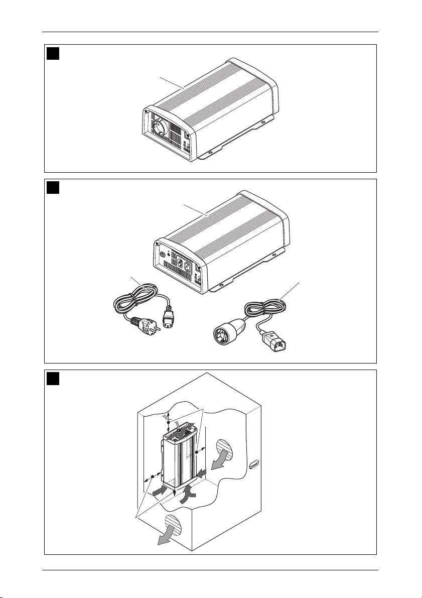
MSI1800T
Pos. in
Abb. 2,
Seite 3
1 Sinus Wechselrichter
2 Anschlusskabel mit Schuko-Kupplung (für 230-Vw-Ausgang)
3 Anschlusskabel mit Schuko-Stecker (für 230-Vw-Versorgung)
– Bedienungsanleitung
Bezeichnung
Bezeichnung
4 Zubehör
Bezeichnung Art.-Nr.
Fernbedienung MCR-7
Fernbedienung MCR-9
5 Zielgruppe dieser Anleitung
Das Kapitel „Wechselrichter anschließen“ auf Seite 20 wendet sich ausschließlich an Fachleute, die mit den entsprechenden VDE-Richtlinien vertraut sind.
Alle übrigen Kapitel wenden sich auch an die Benutzer des Gerätes.
13
Page 14

DE
Bestimmungsgemäßer Gebrauch SinePower
6 Bestimmungsgemäßer Gebrauch
WARNUNG!
!
Die Wechselrichter dienen dazu, Gleichspannung von
12 Vg:
SinePower MSI912, Art.-Nr. 9102600111
SinePower MSI1312, Art.-Nr. 9102600113
SinePower MSI1812, Art.-Nr. 9102600115
SinePower MSI1812T, Art.-Nr. 9102600117
24 Vg:
SinePower MSI924, Art.-Nr. 9102600112
SinePower MSI1324, Art.-Nr. 9102600114
SinePower MSI1824, Art.-Nr. 9102600116
SinePower MSI1824T, Art.-Nr. 9102600118
in eine 200 – 240-V-Wechselspannung von 50 Hz oder 60 Hz zu wandeln.
Der Wechselrichter darf nicht in Fahrzeugen eingesetzt werden,
bei denen der Plus-Pol der Batterie mit dem Chassis verbunden
ist.
14
Page 15

DE
SinePower Technische Beschreibung
7 Technische Beschreibung
Die Wechselrichter lassen sich überall dort betreiben, wo
ein 12-Vg-Anschluss (MSI912, MSI1312, MSI1812, MSI1812T)
ein 24-Vg-Anschluss (MSI924, MSI1324, MSI1824, MSI1824T)
vorhanden ist. Durch das geringe Gewicht und die kompakte Bauweise lässt
sich dieses Gerät problemlos in Reisemobilen, Nutzfahrzeugen oder Motorund Segelyachten einbauen.
Die Ausgangsspannung entspricht der Haushaltsspannung aus der Steckdose (reine Sinusspannung, THD < 3%).
Bitte beachten Sie die Werte für Dauer-Ausgangsleistung und SpitzenAusgangsleistung, wie sie im Kapitel „Technische Daten“ auf Seite 32 angegeben sind. Geräte, die einen höheren Leistungsbedarf haben, dürfen nicht
angeschlossen werden.
HINWEIS
I
Beachten Sie beim Anschluss von Geräten mit elektrischem
Antrieb (z. B. Bohrmaschine, Kühlschrank usw.), dass diese zum
Anlaufen oft eine höhere Leistung benötigen, als auf dem Typenschild angegeben.
Der Wechselrichter besitzt verschiedene Schutzmechanismen:
Überspannungs-Schutz: Der Wechselrichter schaltet ab, wenn der
Spannungswert über den Abschalt-Wert steigt. Er startet wieder, wenn
die Spannung auf den Neustart-Wert sinkt.
Unterspannungs-Schutz: Der Wechselrichter schaltet ab, wenn der
Spannungswert unter den Abschalt-Wert sinkt. Er startet wieder, wenn
die Spannung auf den Neustart-Wert steigt.
Übertemperatur-Schutz: Der Wechselrichter schaltet ab, wenn die
Temperatur innerhalb des Gerätes oder die Temperatur an dem Kühlkörper einen Abschalt-Wert übersteigt. Er startet wieder, wenn die
Spannung auf den Neustart-Wert steigt.
Überlast-Schutz: Die LED am Wechselrichter meldet eine Betriebs-
störung (rotes Dauerlicht), wenn eine zu große Last angeschlossen ist
oder ein Kurzschluss erzeugt wurde. Die Gerätesicherung muss, nachdem sie bei Überstrom ausgelöst hat, manuell wieder eingedrückt
werden.
Verpolungsschutz: Der Verpolungsschutz verhindert beim Anschluss
des Wechselrichter eine falsche Polarität.
15
Page 16

DE
Technische Beschreibung SinePower
Gerätesicherung (nur MSI 1812T und MSI 1824T): Die LED am
Wechselrichter meldet eine Betriebsstörung (rotes Dauerlicht). Die
Gerätesicherung muss, nachdem sie ausgelöst hat, manuell wieder eingedrückt werden.
HINWEIS
I
Zusätzlich kann das Gerät über eine RS-232-Schnittstelle durch einen PC
und mit den DIP-Schaltern am Gerät konfiguriert werden.
Der Wechselrichter kann in einen Energiesparmodus geschaltet werden,
damit die angeschlossene Batterie nicht zu schnell entlädt.
Mit einer Fernbedienung (Zubehör) kann der Wechselrichter bequem gesteuert werden.
Die Wechselrichter SinePower MSI1812T und SinePower MSI1824T sind
mit einer 230-Vw-Vorrangschaltung ausgestattet, Liegt eine externe
230-Vw-Spannung an, so wird diese vorrangig genutzt. Wenn keine externe
230-Vw-Spannung anliegt, so wird zur Spannungsversorgung die angeschlossene Batterie genutzt.
Die einzelnen Schaltwerte finden Sie im Kapitel „Technische Daten“ auf Seite 32.
16
Page 17

DE
SinePower Technische Beschreibung
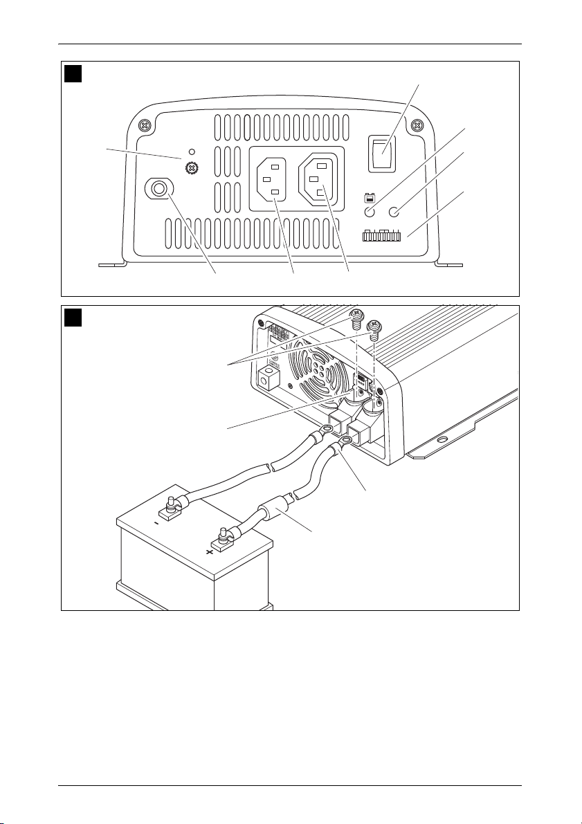
7.1 Bedienelemente
Der Wechselrichter besitzt folgende Anschlüsse, Anzeigen und Bedienelemente an der Rückseite:
Pos. in
Abb. 5,
Seite 4
1 Klemme Einrichtung des Betriebs über Fernbedie-
2 RS232-Schnitt-
3 POS+ Plus-Klemme
4 NEG– Minus-Klemme
5 Masse-Klemme Erdung an der Fahrzeugkarosserie
MSI900, MSI1300, MSI1800
Der Wechselrichter besitzt folgende Anschlüsse, Anzeigen und Bedienelemente an der Vorderseite:
Pos. in
Abb. 6,
Seite 4
Bezeichnung Beschreibung
nung
Anschluss eines PCs über eine serielle
stelle, REMOTEPort
Bezeichnung Beschreibung
RS232-Schnittstelle oder Anschluss der
Fernbedienung MCR-7, MCR-9
1 Hauptschalter
„ON/OFF/
REMOTE“
2 LED „Input Level“ Zeigt den Eingangsspannungsbereich an
3 LED „Load Level“ Zeigt den abgegebenen Leistungsbereich
4 Dipschalter Nimmt Einstellungen am Wechselrichter
5 Schuko-Steck-
dose
Schaltet das Gerät ein, aus oder in den
Betrieb über die Fernbedienung (Zubehör)
an
vor (z. B. Netzspannung, Netzfrequenz,
Energiesparmodus)
230-V-Ausgang
17
Page 18

DE
Technische Beschreibung SinePower
MSI1800T
Der Wechselrichter besitzt folgende Anschlüsse, Anzeigen und Bedienelemente an der Vorderseite:
Pos. in
Abb. 7,
Seite 5
Bezeichnung Beschreibung
1 Hauptschalter
„ON/OFF/
REMOTE“
2 LED „Input Level“ Zeigt den Eingangsspannungsbereich an
3 LED „Load Level“ Zeigt den abgegebenen Leistungsbereich
4 Dipschalter Nimmt Einstellungen am Wechselrichter
5 AC Output 230-V-Ausgang
6 AC Input 230-V-Eingang
7 Sicherung Schützt den Wechselrichter vor Überlas-
8 Erdungsschraube Setzt oder entfernt die Erdungsbrücke
Schaltet das Gerät ein, aus oder in den
Betrieb über die Fernbedienung (Zubehör)
an
vor (z. B. Netzspannung, Netzfrequenz,
Energiesparmodus)
tung.
Die Sicherung kann wieder eingedrückt
werden, nachdem sie ausgelöst hat.
18
Page 19

DE
SinePower Wechselrichter montieren
8 Wechselrichter montieren
8.1 Benötigtes Werkzeug
Für den elektrischen Anschluss benötigen Sie folgende Hilfsmittel:
Krimpzange
3 verschiedenfarbige flexible Anschlusskabel. Den erforderlichen Quer-
schnitt entnehmen Sie der Tabelle im Kapitel „Wechselrichter anschließen“ auf Seite 20.
Kabelschuhe und Aderendhülsen
Für die Befestigung des Wechselrichters benötigen Sie folgende Montagemittel:
Maschinenschrauben (M4) mit Unterlegscheiben und selbstsichernden
Muttern oder
Blech- bzw. Holzschrauben.
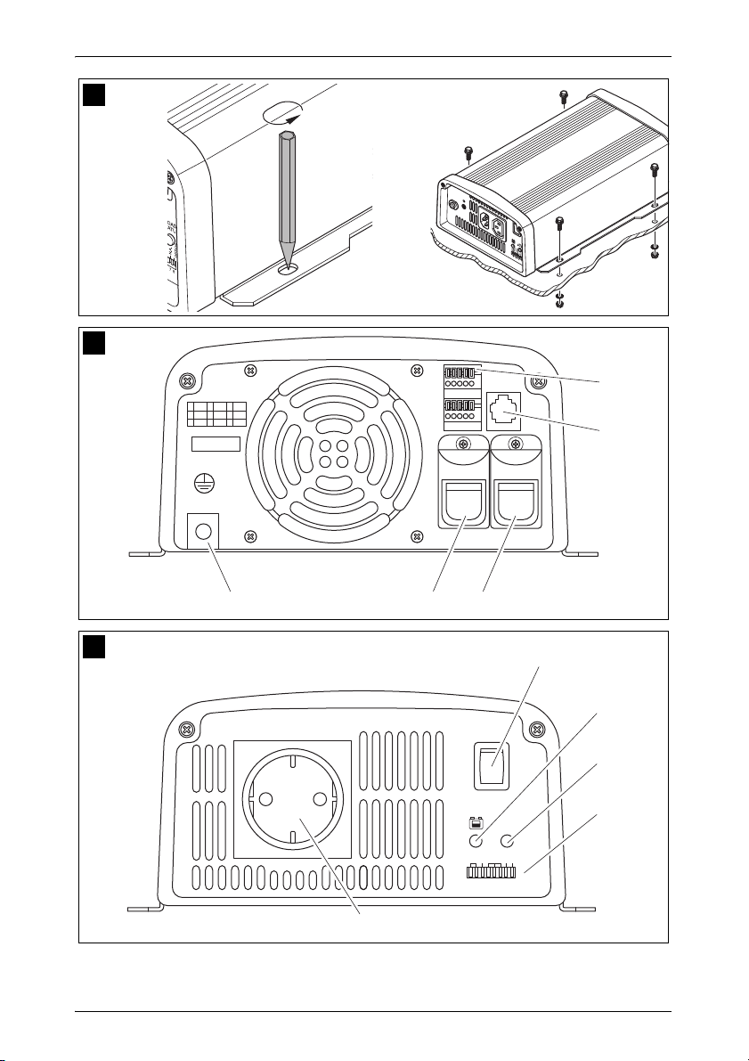
8.2 Montagehinweise
Beachten Sie bei der Wahl des Montageortes folgende Hinweise:
Die Montage des Wechselrichters kann horizontal wie auch vertikal
erfolgen.
Der Wechselrichter muss an einer vor Feuchtigkeit geschützten Stelle
eingebaut werden.
Der Wechselrichter darf nicht in Umgebungen mit entflammbaren
Materialien eingebaut werden.
Der Wechselrichter darf nicht in staubigen Umgebungen eingebaut
werden.
Der Einbauort muss gut belüftet sein. Bei Installationen in geschlossenen
kleinen Räumen sollte eine Be- und Entlüftung vorhanden sein. Der freie
Mindestabstand um den Wechselrichter muss mindestens 25 cm betragen (Abb. 3, Seite 3).
Der Lufteintritt auf der Unterseite bzw. der Luftaustritt auf der Rückseite
des Wechselrichters muss freibleiben.
Bei Umgebungstemperaturen, die höher als 40 °C (z. B. in Motor- oder
Heizungsräumen, direkte Sonneneinstrahlung) sind, kann es durch die
Eigenerwärmung des Wechselrichters bei Belastung zum automatischen
Abschalten kommen.
19
Page 20

DE
Wechselrichter anschließen SinePower
Die Montagefläche muss eben sein und eine ausreichende Festigkeit auf-
weisen.
ACHTUNG!
A
Bevor Sie irgendwelche Bohrungen vornehmen, stellen Sie sicher, dass keine elektrischen Kabel oder andere Teile des Fahrzeugs durch Bohren, Sägen und Feilen beschädigt werden.
8.3 Wechselrichter montieren
➤ Halten Sie den Wechselrichter an den von Ihnen gewählten Einbauort
und markieren Sie die Befestigungspunkte (Abb. 4 A, Seite 4).
➤ Befestigen Sie den Wechselrichter mit der von Ihnen gewählten
Befestigungsmethode (Abb. 4 B, Seite 4).
9 Wechselrichter anschließen
9.1 Allgemeine Hinweise
WARNUNG!
!
Der Anschluss des Wechselrichters darf ausschließlich von
entsprechend ausgebildeten Fachbetrieben durchgeführt werden. Die nachfolgenden Informationen richten sich an Fachkräfte, die mit den anzuwendenden Richtlinien und
Sicherheitsvorkehrungen vertraut sind.
Bei Fahrzeugen, bei denen der Plus-Pol der Batterie mit dem
Chassis verbunden ist, darf der Wechselrichter nicht eingesetzt werden.
Wenn Sie keine Sicherung in die Plus-Leitung setzen, kön-
nen die Leitungen überlastet werden, und es kann zu einem
Brand kommen.
Verpolung kann zu Zerstörung des Wechselrichters führen.
MSI900, MSI1300, MSI1800: Der Wechselrichter darf nicht in
einem Ringleitungsnetz verwendet werden, sondern nur um
einzelne Geräte mit Strom zu versorgen. Diese Geräte müssen direkt in den Wechselrichter eingesteckt oder mit einem
für diesen Zweck hergestellten, umspritzten Verlängerungskabel mit dem Wechselrichter verbunden werden.
20
Page 21

DE
SinePower Wechselrichter anschließen
Der Wechselrichter muss bei Installationen in Fahrzeugen oder Booten
mit dem Chassis bzw. der Masse verbunden sein.
Halten Sie beim Aufbau eines Steckdosenverteilerkreises (Netzaufbau)
die Vorschriften der VDE 0100 ein.
Verwenden Sie ausschließlich Kupferkabel.
Halten Sie die Kabel so kurz wie möglich (< 1,8 m).
Halten Sie den erforderlichen Kabelquerschnitt ein und setzen Sie eine
Kabelsicherung (Abb. 8 3, Seite 5) möglichst nah an der Batterie in die
Plus-Leitung (siehe Tabelle).
Gerät
MSI912 25 mm² 115 A
MSI924 25 mm² 75 A
MSI1312 35 mm² 170 A
MSI1324 35 mm² 85 A
MSI1812/MSI1812T 35 mm² 228 A
MSI1824/MSI1824T 35 mm² 115 A
erforderlicher
Kabelquerschnitt
Kabelsicherung
(Abb. 8 3, Seite 5)
9.2 Wechselrichter an Batterie anschließen
HINWEIS
I
➤ Stellen Sie den Hauptschalter (Abb. 6 1, Seite 4 und Abb. 7 1, Seite 5)
auf „OFF“.
➤ Lösen Sie die Schraube (Abb. 8 1, Seite 5) aus der roten Plus-Klemme
(Abb. 8 2, Seite 5).
➤ Schieben Sie den Kabelschuh (Abb. 8 2, Seite 5) des Plus-Kabels in die
rote Plus-Klemme und befestigen Sie ihn mit der Schraube.
Ziehen Sie die Schrauben oder Muttern mit einem Drehmoment
von 12 – 13 Nm fest. Lose Verbindungen können zu Überhitzungen führen.
➤ Schließen Sie das Minus-Kabel entsprechend an der schwarzen Minus-
Klemme (Abb. 8 4, Seite 5) an.
➤ Verlegen Sie das Plus-Kabel vom Wechselrichters zum Pluspol der Fahr-
zeug-Batterie und schließen Sie es dort an.
21
Page 22

DE
Wechselrichter anschließen SinePower
➤ Verlegen Sie das Minus-Kabel vom Wechselrichters zum Minuspol der
Fahrzeug-Batterie und schließen Sie es dort an.
➤ Verbinden Sie die Masse-Klemme mit der Fahrzeugkarosserie.
9.3 230-V-Versorgungsleitung anschließen
(nur MSI1800T)
➤ Stecken Sie das 230-Vw-Anschlusskabel mit Schuko-Stecker in die
230-Vw-Eingangsbuchse (Abb. 7 6, Seite 5).
➤ Schließen Sie den Schuko-Stecker an das 230-V-Wechselstromnetz an.
9.4 230-V-Ausgangsleitung anschließen
(nur MSI1800T)
WARNUNG!
!
➤ Stecken Sie das 230-Vw-Anschlusskabel mit Schuko-Kupplung in die
230-Vw-Ausgangsbuchse (Abb. 7 5, Seite 5).
Stellen Sie vor dem Anschließen der 230-V-Ausgangsleitung
sicher, dass der Wechselrichter mit dem Hauptschalter ausgeschaltet ist.
22
Page 23

DE
SinePower Wechselrichter anschließen
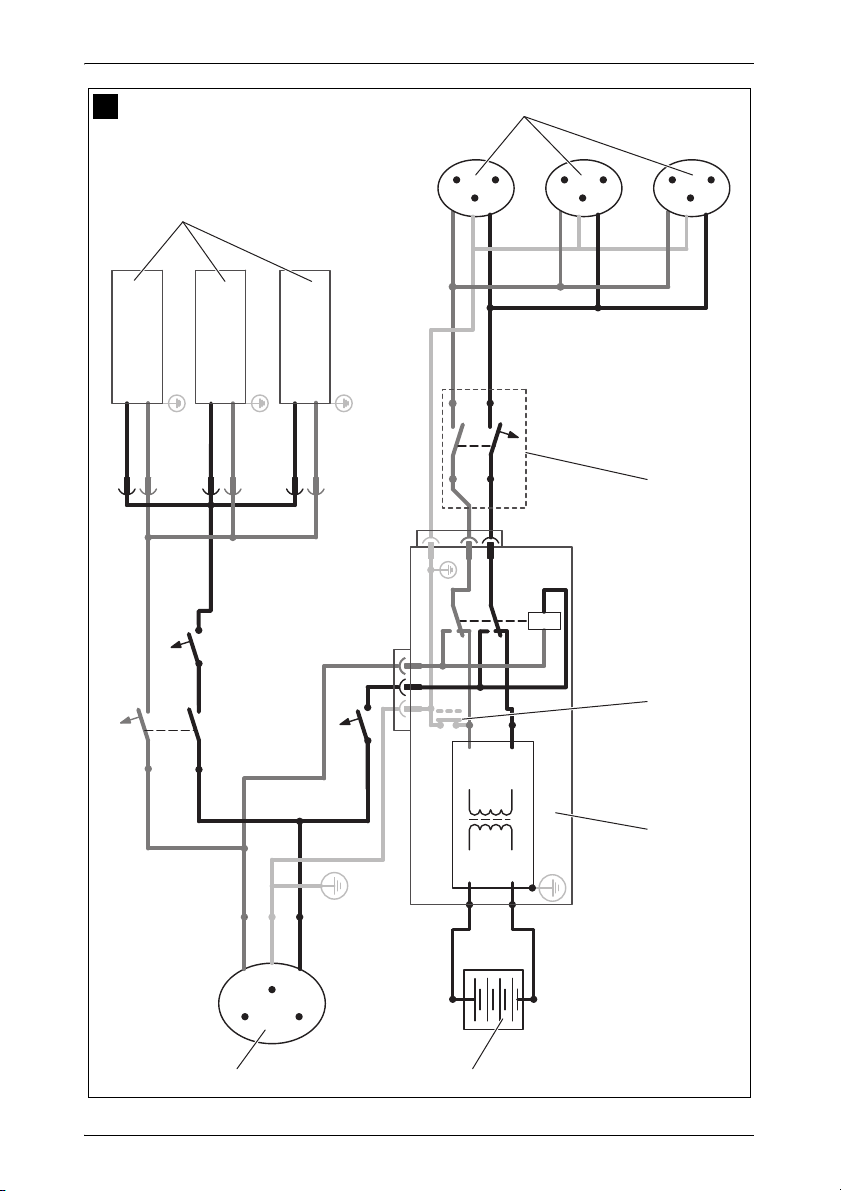
9.5 Mehrere Verbraucher anschließen
(nur MSI1800T)
Das Gerät ist im Lieferzustand mit galvanischer Trennung ausgestattet. Zum
sicheren Betrieb von mehreren Verbrauchern ist es zwingend notwendig,
dass im Steckdosenverteilerkreis ein Schutzschalter (FI-Schalter) eingebaut
wird, siehe Beispiel-Schaltplan in Abb. 9, Seite 6.
Legende zum Beispiel-Schaltplan:
Pos. in
Abb. 9,
Seite 6
1 230-Vw-Spannungsquelle
2 weitere Geräte wie z. B. Batterielader, Kühlschrank
3 DC-Spannungsquelle (Batterie)
4 Wechselrichter
5 Erdungsbrücke gesetzt (Lieferzustand: nicht gesetzt, gestri-
6 Schutzschalter (FI-Schalter)
7 Steckdosenverteilerkreis für Verbraucher
Erklärung
chelt dargestellt)
WARNUNG! Lebensgefahr durch Stromschlag!
!
➤ Bauen Sie einen FI-Schalter in den Steckdosenverteilerkreis ein.
Wenn Sie mehr als einen Verbraucher an den Wechselrichter anschließen wollen und dazu einen Steckdosenverteilerkreis aufbauen, müssen Sie einen Schutzschalter (FI-Schalter) vorsehen
und die Erdungsbrücke im Wechselrichter setzen.
9.6 Erdungsbrücke setzen (Abb. 7 8, Seite 5)
(nur MSI1800T)
➤ Schrauben Sie die Erdungsschraube aus der unteren Bohrung heraus.
➤ Schrauben Sie die Schraube in die obere Bohrung ein.
23
Page 24

DE
Wechselrichter anschließen SinePower
9.7 Fernbedienung MCR-7 oder MCR-9 (Zubehör)
anschließen
ACHTUNG!
A
➤ Schließen Sie die Fernbedienung (Zubehör) am Remote-Port (Abb. 5 2,
Seite 4) an.
Stecken Sie den Anschluss zur Fernbedienung nur in den Re-
mote-Port. Durch falsches Anschließen kann das Gerät beschädigt werden.
Stellen Sie sicher, dass Fernbedienung und Wechselrichter
mitdemselben Eingangsspannungswert versorgt werden.
Beachten Sie die Anleitung der Fernbedienung.
9.8 Externen Schalter zum Ein- und Ausschalten
anschließen
HINWEIS
I
Als externen Schalter können Sie folgendes verwenden:
externer Schalter, Spannungsversorgung aus dem Wechselrichter:
Abb. 0, Seite 7
Steuereinheit mit Relais- oder Transistorbeschaltung (TR): Abb. a,
Seite 7
externer Schalter mit Spannungsversorgung über die Batterie (BAT) des
Fahrzeuges: Abb. b, Seite 7
externer Schalter mit eigener Spannungsversorgung (DC POWER), z. B.
von der Zündung: Abb. c, Seite 7
Verwenden Sie Kabel mit einem Kabelquerschnitt von 0,25 –
0,75 mm².
➤ Stellen Sie den Hauptschalter (Abb. 6 1, Seite 4 und Abb. 7 1, Seite 5)
auf „OFF“ und stellen Sie sicher, dass der Anschluss für die Fernbedienung (Abb. 5 2, Seite 4) nicht belegt ist.
➤ Stellen Sie den Hauptschalter (Abb. 6 1, Seite 4 und Abb. 7 1, Seite 5)
auf „REMOTE“.
➤ Schließen Sie den externen Ein-/Aus-Schalter mit dem Anschlusskabel
an der Klemme (Abb. 5 1, Seite 4) an.
24
Page 25

DE
SinePower Wechselrichter anschließen
9.9 Pin-Belegungen
HINWEIS
I
Die Pins des RS232-Ports sind wie folgt belegt:
Halten Sie die Kabellängen so kurz wie möglich (<10 m), damit es
keine Verluste bei der Signalübertragung gibt.
Wechselrichter Computer
Pin Beschreibung Beschreibung Pin
1 Nicht belegt Nicht belegt 1
2 GND RXD 2
3RXDTXD3
4TXDDTR4
5 Nicht belegt GND 5
6 Nicht belegt DSR 6
RTS 7
CTS 8
Nicht belegt 9
Die Pins des RJ11-Anschlusses für Fernbedienung sind wie folgt belegt:
Wechselrichter
Pin Beschreibung
1–
2GND
3RS232 RXD
4 RS232 TXD
5 RMT Fernbedienung
6 Nicht belegt
25
Page 26

DE
Wechselrichter benutzen SinePower
10 Wechselrichter benutzen
10.1 Wechselrichter einschalten
➤ Stellen Sie den Hauptschalter (Abb. 6 1, Seite 4 und Abb. 7 1, Seite 5)
des Wechselrichters in Schalterstellung „ON“.
Zum Ausschalten stellen Sie den Ein/Aus-Schalter auf „OFF“.
➤ Der Wechselrichter führt einen Selbsttest durch.
Während der Selbstdiagnose gibt der interne Lautsprecher Töne ab und
die LEDs blinken.
✓ Nach dem erfolgreichen Selbsttest leuchtet die LEDs „Input Level“
(Abb. 6 2, Seite 4 und Abb. 7 2, Seite 5) und „Load Status“ (Abb. 6 3,
Seite 4 und Abb. 7 3, Seite 5) grün.
Beachten Sie im Betrieb folgende Hinweise (siehe auch Kapitel „Fehlerbeseitigung“ auf Seite 30)
Der Wechselrichter schaltet sich ab, wenn
die Batteriespannung unter 10,5 V (12 Vg-Anschluss) bzw. 21 V
(24 Vg-Anschluss) sinkt,
die Batteriespannung über 16 V (12 Vg-Anschluss) bzw. 32 V
(24 Vgw-Anschluss) steigt,
der Wechselrichter überhitzt wird.
➤ Schalten Sie den Wechselrichter in diesem Fall mit dem Hauptschalter
(Abb. 6 1, Seite 4 und Abb. 7 1, Seite 5) aus.
➤ Kontrollieren Sie, ob der Wechselrichter genügend belüftet ist und ob die
Lüfteröffnungen und Belüftungsschlitze frei sind.
➤ Warten Sie ca. 5 – 10 min und schalten Sie den Wechselrichter ohne Ver-
braucher wieder ein.
Beim Betreiben des Wechselrichters über längere Zeit und mit größter
Belastung empfiehlt es sich, den Motor zu starten, um die Batterie des Fahrzeuges wieder aufzuladen.
26
Page 27

DE
SinePower Wechselrichter benutzen
10.2 Betriebsanzeigen
LED „Input Level“ (Abb. 6 2, Seite 4 und Abb. 7 2, Seite 5)
Die LED „Input Level“ zeigt den Spannungsbereich an, in dem sich die
Eingangsspannung befindet.
Anzeige Eingangsspannung
MSI912, MSI1312,
MSI1812, MSI 1812T
Rot, langsames Blinken <10,6 V <21,2 V
Rot 10,6 – 11,0 V 21,2 – 22,0 V
Orange 11,0 – 12,0 V 22,0 – 24,0 V
Grün 12,0 – 14,2 V 24,0 – 28,4 V
Orange, blinkend 14,2 – 15,0 V 28,4 – 30,0 V
Rot, schnelles Blinken >15,0 >30,0
LED „Load Level“ (Abb. 6 3, Seite 4 und Abb. 7 3, Seite 5)
Die LED „Load Level“ zeigt den Leistungsbereich an, der vom Wechselrichter abgegeben wird.
Anzeige Eingangsspannung
MSI 912,
MSI924
Aus 0 – 80 W 0 – 120 W 0 – 160 W
Grün 80 – 320 W 120 – 480 W 160 – 640 W
Orange 320 – 720 W 480 – 1080 W 640 – 1440 W
Rot, langsames Blinken 720 – 800 W 1080 – 1200 W 1440 – 1600 W
Rot, schnelles Blinken >800 W >1200 W >1600 W
MSI1312,
MSI1324
MSI924, MSI1324,
MSI1824, MSI1824T
MSI1812,
MSI1812T,
MSI1824,
MSI1824T
27
Page 28

DE
Wechselrichter benutzen SinePower
10.3 Wechselrichter einstellen
HINWEIS
I
Sie können das Gerät mit Hilfe der Dip-Schalter (Abb. 6 4, Seite 4 und
Abb. 7 4, Seite 5) anpassen.
Netzspannung einstellen
Mit den Dip-Schaltern S1 und S2 können Sie die Netzspannung einstellen.
Die Einstellungen über die Dip-Schalter werden nur dann übernommen, wenn sich der Dip-Schalter S8 in der Position „Ein“
befindet.
Dip-Schalter
Netzspannung S1 S2
200 V Aus Aus
220 V Ein Aus
230 V Aus Ein
240 V Ein Ein
Netzfrequenz einstellen
WARNUNG! Lebensgefahr durch Stromschlag!
!
Mit dem Dip-Schalter S3 können Sie die Netzfrequenz einstellen.
Energiesparmodus einstellen
Mit den Dip-Schaltern S4, S5 und S6 können Sie den Energiesparmodus einstellen. Dadurch wird die Batterie, an der Sie den Wechselrichter anschließen, nicht so schnell entladen.
Verstellen Sie DIP-Schalter S3 nur, wenn die entsprechende
Frequenz für die Ausgangsspannung verwendet werden soll.
Dip-Schalter
Netzfrequenz S3
50 Hz Aus
60 Hz Ein
28
Page 29

DE
SinePower Wechselrichter pflegen und reinigen
Der Wechselrichter arbeitet dann im Energiesparmodus, solange die
geforderte Leistung unter dem eingestellten Leistungswert liegt. Wenn die
benötigte Leistung über dem eingestellten Leistungswert liegt, arbeitet der
Wechselrichter im Normalbetrieb.
Die einzustellenden Werte für Ihren Wechselrichter entnehmen Sie bitte der
folgenden Tabelle:
Energiesparmodus Dip-Schalter
MSI900 MSI1300 MSI1800 S4 S5 S6
Aus Aus Aus Aus Aus Aus
– <60 W <110 W Ein Aus Aus
<70 W <130 W <180 W Ein Ein Aus
<200 W <210 W <220 W Ein Ein Ein
Einstellungen festlegen
Mit dem Dip-Schalter S8 können Sie festlegen, ob die Werkseinstellungen
oder die Einstellungen der Dip-Schalter S1-S7 verwendet werden sollen.
Dip-Schalter
Parameter S8
Werkseinstellungen Aus
Dip-Schalter S1-S7 verwenden Ein
11 Wechselrichter pflegen und reinigen
ACHTUNG!
A
➤ Reinigen Sie das Produkt gelegentlich mit einem feuchten Tuch.
Keine scharfen oder harten Gegenstände oder Reinigungsmittel
zur Reinigung verwenden, da dies zu einer Beschädigung des
Produktes führen kann.
29
Page 30

DE
Fehlerbeseitigung SinePower
12 Fehlerbeseitigung
WARNUNG!
!
I
Die „Load Status“ (Abb. 6 3, Seite 4 und Abb. 7 3, Seite 5) zeigt rot den
Fehler an:
LED-Anzeige Ursache Behebung
Schnelles Blinken Zu hohe Eingangsspannung Prüfen Sie die Eingangsspannung
Langsames Blinken Zu niedrige Eingangs-
Periodisches Blinken Thermische Überlastung Schalten Sie den Wechselrichter und
Öffnen Sie das Gerät nicht. Sie setzen sich der Gefahr eines
elektrischen Schlages aus!
HINWEIS
Bei detaillierten Fragen zu den Daten des Wechselrichters
wenden Sie sich bitte an den Hersteller (Adressen siehe Rückseite der Anleitung).
und reduzieren Sie diese.
Die Batterie muss nachgeladen wer-
spannung
den.
Prüfen Sie die Leitungen und Verbin-
dungen.
den Verbraucher aus.
Warten Sie ca. 5 – 10 Minuten und
schalten Sie den Wechselrichter
ohne Verbraucher wieder ein.
Reduzieren Sie die Belastung und
sorgen Sie für eine bessere Belüftung des Wechselrichters. Schalten
Sie dann den Verbraucher wieder
ein.
30
Page 31

DE
SinePower Gewährleistung
LED-Anzeige Ursache Behebung
Dauerleuchten Kurzschluss oder Verpolung
Zu hohe Belastung
Schalten Sie den Wechselrichter aus
und entfernen Sie den Verbraucher.
Schalten Sie den Wechselrichter
ohne Verbraucher wieder ein. Wird
jetzt keine zu hohe Belastung mehr
angezeigt, so liegt ein Kurzschluss
beim Verbraucher vor oder die
Gesamtbelastung war höher als die
im Datenblatt spezifizierte Leistung.
MSI 1812T und MSI 1824T: Die
Gerätesicherung muss, nachdem sie
ausgelöst hat, manuell wieder eingedrückt werden.
Prüfen Sie die Leitungen und Verbindungen.
13 Gewährleistung
Es gilt die gesetzliche Gewährleistungsfrist. Sollte das Produkt defekt sein,
wenden Sie sich bitte an die Niederlassung des Herstellers in Ihrem Land
(Adressen siehe Rückseite der Anleitung) oder an Ihren Fachhändler.
Zur Reparatur- bzw. Gewährleistungsbearbeitung müssen Sie folgende
Unterlagen mitschicken:
eine Kopie der Rechnung mit Kaufdatum,
einen Reklamationsgrund oder eine Fehlerbeschreibung.
14 Entsorgung
➤ Geben Sie das Verpackungsmaterial möglichst in den entsprechenden
Recycling-Müll.
Wenn Sie das Produkt endgültig außer Betrieb nehmen, informieren Sie sich bitte beim nächsten Recyclingcenter oder bei
M
Ihrem Fachhändler über die zutreffenden Entsorgungsvorschriften.
31
Page 32

DE
Technische Daten SinePower
15 Technische Daten
HINWEIS
I
Art.-Nr.: 9102600111 9102600112
Eingangsnennspannung: 12 Vg 24 Vg
Ausgangsleistung
bei 25 °C für 10 min:
Spitzen-Ausgangsleistung: 1600 W
Ausgangsspannung: 200 – 240 Vw reine Sinuswelle (THD < 3%)
Ausgangsfrequenz: 50 oder 60 Hz
Leerlaufstromaufnahme: 1,8 A 1,0 A
Bereitschaftstromauf-
nahme:
Eingangsspannungs-
bereich:
Wirkungsgrad bis zu: 89 % 91 %
Umgebungstemperatur
Betrieb:
Umgebungstemperatur
Lagerung:
Vorrangschaltung: 230-V-Eingangssicherung: 10 A
Abmessungen B x T x H: 197,5 x 94,3 x 291 mm, siehe Abb. d, Seite 8
Gewicht: 4 kg
Bei thermischer Überlastung reagiert der Wechselrichter und reduziert bei einer Temperatur von über 40 °C die Leistung.
Bei einer Temperatur von über 60 °C schaltet sich der Wechselrichter ab.
MSI912 MSI924
900 W
0,5 A 0,3 A
10,5 V – 16 V 21 V – 32 V
–20 °C bis 40 °C
40 °C bis 60 °C (reduzierte Leistung)
–30 °C bis +70 °C
Umschaltzeit Bypassrelais: < 30 mSek
32
Page 33

DE
SinePower Technische Daten
MSI1312 MSI1324
Art.-Nr.: 9102600113 9102600114
Eingangsnennspannung: 12 Vg 24 Vg
Ausgangsleistung
bei 25 °C für 10 min:
Spitzen-Ausgangsleistung: 2400 W
Ausgangsspannung: 200 – 240 Vw reine Sinuswelle (THD < 3%)
Ausgangsfrequenz: 50 oder 60 Hz
Leerlaufstromaufnahme: 2,1 A 1,1 A
Bereitschaftstromauf-
nahme:
Eingangsspannungs-
bereich:
Wirkungsgrad bis zu: 90 % 91 %
Umgebungstemperatur
Betrieb:
Umgebungstemperatur
Lagerung:
Vorrangschaltung: 230-V-Eingangssicherung: 10 A
Abmessungen B x T x H: 197,5 x 94,3 x 324,6 mm, siehe Abb. d, Seite 8
Gewicht: 5 kg
0,5 A 0,3 A
10,5 V – 16 V 21 V – 32 V
40 °C bis 60 °C (reduzierte Leistung)
Umschaltzeit Bypassrelais: < 30 mSek
1300 W
–20 °C bis 40 °C
–30 °C bis +70 °C
33
Page 34

DE
Technische Daten SinePower
MSI1812 MSI1812T MSI1824 MSI 1824T
Art.-Nr.: 9102600115 9102600117 9102600116 9102600118
Eingangsnennspannung: 12 Vg 24 Vg
Ausgangsleistung
bei 25 °C für 10 min:
Spitzen-Ausgangsleistung: 3200 W
Ausgangsspannung: 200 – 240 Vw reine Sinuswelle (THD < 3%)
Ausgangsfrequenz: 50 oder 60 Hz
Leerlaufstromaufnahme: 2.1 A 1,1 A
Bereitschaftstromauf-
nahme:
Eingangsspannungs-
bereich:
Wirkungsgrad bis zu: 92 % 92 %
Überbrückungsrelais: – 25 A/277 Vw – 25 A/277 Vw
Umgebungstemperatur
Betrieb:
Umgebungstemperatur
Lagerung:
Vorrangschaltung: 230-V-Eingangssicherung: 10 A
Abmessungen B x T x H: 197,5 x 94,3 x
376 mm
Abb. d,
Seite 8
Gewicht: 5,5 kg 6 kg 5,5 kg 6 kg
0,5 A 0,3 A
10,5 V – 16 V 21 V – 32 V
40 °C bis 60 °C (reduzierte Leistung)
Umschaltzeit Bypassrelais: < 30 mSek
197,5 x 94,3 x
siehe
Abb. d,
1800 W
–20 °C bis 40 °C
–30 °C bis +70 °C
406 mm
siehe
Seite 8
197,5 x 94,3 x
376 mm
siehe
Abb. d,
Seite 8
197,5 x 94,3 x
406 mm
siehe
Abb. d,
Seite 8
34
Page 35

DE
SinePower Technische Daten
E
Überspannungs-Schutz
Gerät
MSI912, MSI1312,
MSI1812, MSI1812T
MSI924, MSI1324,
MSI1824, MSI1824T
Abschaltung Neustart
16 V 14,5 V
32 V 29 V
Überspannung
Unterspannungs-Schutz
Gerät
MSI912, MSI1312,
MSI1812, MSI1812T
MSI924, MSI1324,
MSI1824, MSI1824T
Unterspannungs-
warnung
11 V 10,5 V 12,5 V
22 V 21 V 25 V
Abschaltung Neustart
Unterspannung
Übertemperatur-Schutz
Temperatur intern Temperatur am Kühlkörper
Abschaltung Neustart Abschaltung Neustart
60 °C 40 °C 95 °C <80 °C
Zulassungen
Das Gerät hat die E13-Zulassung.
Gemäß der EMV Richtlinie 2004/108/EC inklusive 2009/19/EC und Niederspannungsrichtlinie 2006/95/EC
EN55012: Class B
EN55014:Class B
EN61000-6-1/6-3: Class B
EN61000-6-2/6-4: Class A
EN61204-3
35
Page 36

EN
SinePower
Please read this instruction manual carefully before installation and
first use, and store it in a safe place. If you pass on the product to another person, hand over this instruction manual along with it.
Table of contents
1 Explanation of symbols . . . . . . . . . . . . . . . . . . . . . . . . . . . . . . . . . . 37
2 General safety instructions . . . . . . . . . . . . . . . . . . . . . . . . . . . . . . . 37
3 Scope of delivery . . . . . . . . . . . . . . . . . . . . . . . . . . . . . . . . . . . . . . . 39
4 Accessories . . . . . . . . . . . . . . . . . . . . . . . . . . . . . . . . . . . . . . . . . . . 40
5 Target group for this manual . . . . . . . . . . . . . . . . . . . . . . . . . . . . . . 40
6 Intended use . . . . . . . . . . . . . . . . . . . . . . . . . . . . . . . . . . . . . . . . . . 40
7 Technical description . . . . . . . . . . . . . . . . . . . . . . . . . . . . . . . . . . . . 41
8 Fitting the inverter . . . . . . . . . . . . . . . . . . . . . . . . . . . . . . . . . . . . . . 45
9 Connecting the inverter . . . . . . . . . . . . . . . . . . . . . . . . . . . . . . . . . . 46
10 Using the inverter. . . . . . . . . . . . . . . . . . . . . . . . . . . . . . . . . . . . . . . 52
11 Cleaning and caring for the inverter. . . . . . . . . . . . . . . . . . . . . . . . . 55
12 Troubleshooting . . . . . . . . . . . . . . . . . . . . . . . . . . . . . . . . . . . . . . . . 56
13 Warranty . . . . . . . . . . . . . . . . . . . . . . . . . . . . . . . . . . . . . . . . . . . . . 57
14 Disposal . . . . . . . . . . . . . . . . . . . . . . . . . . . . . . . . . . . . . . . . . . . . . . 57
15 Technical data . . . . . . . . . . . . . . . . . . . . . . . . . . . . . . . . . . . . . . . . . 58
36
Page 37

EN
SinePower Explanation of symbols
1 Explanation of symbols
WARNING!
!
A
I
➤ Action: This symbol indicates that action is required on your part. The
required action is described step-by-step.
✓ This symbol describes the result of an action.
Fig. 1 5, page 3: This refers to an element in an illustration. In this case,
item 5 in figure 1 on page 3.
Safety instruction: Failure to observe this instruction can cause
fatal or serious injury.
NOTICE!
Failure to observe this instruction can cause material damage and
impair the function of the product.
NOTE
Supplementary information for operating the product.
2 General safety instructions
2.1 General safety
The manufacturer accepts no liability for damage in the following cases:
Faulty assembly or connection
Damage to the product resulting from mechanical influences and excess
voltage
Alterations to the product without express permission from the manu-
facturer
Use for purposes other than those described in the operating manual
WARNING!
!
Only use the device as intended.
Do not operate the device in a damp or wet environment.
Do not operate the device near any flammable materials.
37
Page 38

EN
General safety instructions SinePower
Do not operate the device in areas that are potentially explo-
sive.
Maintenance and repair work may only be carried out by quali-
fied personnel who are familiar with the risks involved and the
relevant regulations.
People (including children) whose physical, sensory or mental
capacities or whose lack of experience or knowledge prevent
them from using this product safely should not use it without the
supervision or instruction of a responsible person.
Electrical devices are not toys
Always keep and use the device out of the reach of children.
2.2 Safety when installing the device
WARNING!
!
Installing the device may only be performed by qualified person-
nel who are familiar with the guidelines and safety precautions
to be applied.
If electrical devices are incorrectly installed on boats, corrosion
damage might occur. The device should be installed by a specialist (marine) electrician.
A
38
NOTICE!
Ensure that the device is standing firmly.
The device must be set up and fastened in such a way that it
cannot tip over or fall down.
Do not expose the device to a heat source (such as direct sun-
light or heating). Avoid additional heating of the device in this
way.
If cables have to be fed through metal walls or other walls with
sharp edges, use ducts or tubes to prevent damage.
Do not lay cables which are loose or bent next to electrically
conductive material (metal).
Do not pull on the cables.
Do not lay the 230 V mains cable and the 12/24 V DC cable in
the same duct.
Fasten the cables securely.
Lay the cables so that they cannot be tripped over or damaged.
Page 39

EN
SinePower Scope of delivery
2.3 Operating the device safely
WARNING!
!
A
Operate the device only if you are certain that the housing and
the cables are undamaged.
Even after the fuse triggers, parts of the inverter remain live.
Always disconnect the power supply when working on the de-
vice.
NOTICE!
Make sure the air inlets and outlets of the device are not cov-
ered.
Ensure good ventilation. The inverter produces dissipated heat
which has to be diverted.
Do not connect the 230 V output of the inverter (fig. 6 5,
page 4 and fig. 7 5, page 5) to a different 230 V source.
3 Scope of delivery
MSI900, MSI1300, MSI1800
No. in
fig. 1,
page 3
1 Sine wave inverter
– Operating manual
MSI1800T
No. in
fig. 2,
page 3
1 Sine wave inverter
2 Connection cable with safety coupling (for 230 Vw output)
3 Connection cable with safety plug (for 230 Vw supply)
– Operating manual
Designation
Designation
39
Page 40

EN
Accessories SinePower
4 Accessories
Designation Item no.
Remote control MCR-7
Remote control MCR-9
5 Target group for this manual
The electrical installation (chapter “Connecting the inverter” on page 46) is
intended for professionals who are familiar with the applicable regulations of
the country in which the equipment is to be installed and/or used.
All other chapters are intended for the users.
6 Intended use
WARNING!
!
Never use the inverter on vehicles where the positive terminal of
the battery is connected to the chassis.
The wave inverter converts direct current of
12 Vg:
SinePower MSI912, item no. 9102600111
SinePower MSI1312, item no. 9102600113
SinePower MSI1812, item no. 9102600115
SinePower MSI1812T, item no. 9102600117
24 Vg:
SinePower MSI924, item no. 9102600112
SinePower MSI1324, item no. 9102600114
SinePower MSI1824, item no. 9102600116
SinePower MSI1824T, item no. 9102600118
into a 200 – 240 V AC supply of 50 Hz or 60 Hz.
40
Page 41

EN
SinePower Technical description
7 Technical description
The inverters can be operated wherever
a 12 Vg connection (MSI912, MSI1312, MSI1812, MSI1812T)
a 24 Vg connection (MSI924, MSI1324, MSI1824, MSI1824T)
is available. The light-weight and compact construction of this device allows
for easy installation in mobile homes, commercial vehicles or motor and sailing yachts.
The output voltage corresponds to the household voltage from the socket
(pure sine wave, THD < 3%).
Please observe the values for constant output power and peak output power
as indicated in chapter “Technical data” on page 58 . Never connect devices
that have a higher power requirement.
NOTE
I
The inverter has various protective mechanisms.
Overvoltage shutdown: The inverter shuts itself off when the voltage ex-
ceeds the cut-off value. It restarts when the voltage returns to the restart
value.
Undervoltage shutdown: The inverter shuts itself off when the voltage
sinks below the cut-off value. It restarts when the voltage rises to the restart value.
Excess temperature shutdown: The inverter switches off when the tem-
perature inside the device or the temperature on the cooling element exceeds a cut-off value. It restarts when the voltage rises to the restart
value.
Overload shutdown: The LED on the inverter indicates an operating
fault (constant red light) when an excess load is connected or a short circuit has occurred. The fuse in the device must be pressed in again by
hand after it is triggered by excess current.
Incorrect polarity protection: The incorrect polarity protection prevents
the wrong polarity when connecting the inverter.
Fuses (MSI 1812T and MSI 1824T only): The LED on the inverter indi-
cates an operating fault (constant red light). The fuse in the device must
be pressed in again by hand after it is triggered.
Note when connecting devices with an electrical drive (such as
power drills and refrigerators), that they often require more power
than is indicated on the type plate.
41
Page 42

EN
Technical description SinePower
NOTE
I
The device can also be configured with a PC via an RS 232 interface and using the DIP switches on the device.
The inverter can be switched to an energy-saving mode to prevent the connected battery from discharging too quickly.
The inverter can be easily controlled using the remote control (accessory).
The SinePower MSI1812T and SinePower MSI1824T inverters are fitted
with a 230 Vw priority circuit. If an external 230 Vw voltage is available, this
will have priority. If no external 230 Vw voltage is connected, then the connected battery will be used as the power supply.
The individual values are found in the chapter “Technical data” on
page 58.
7.1 Control elements
The inverter has the following connections, displays and control elements on
the back:
No. in
fig. 5,
page 4
Designation Description
1 Terminal Setup operation via remote control
2 RS232 port,
REMOTE port
3 POS+ Positive terminal
4 NEG– Negative terminal
5 Earth terminal Earthing on the vehicle bodywork
Connection of a PC using a serial RS232
interface or connection of the MCR-7 or
MCR-9 remote control
42
Page 43

EN
SinePower Technical description
MSI900, MSI1300, MSI1800
The inverter has the following connections, displays and control elements on
the front:
No. in
fig. 6,
page 4
Designation Description
1 Main switch
“ON/OFF/
REMOTE”
switch:
2 “Input Level” LED Displays the input voltage range
3 “Load Level” LED Displays the power being supplied
4 Dip switch Makes settings on the inverter (such as
5 Safety socket 230 V output
Switches the device on, off or to operation
via the remote control (accessory)
mains voltage, mains frequency, energysaving mode).
43
Page 44

EN
Technical description SinePower
MSI1800T
The inverter has the following connections, displays and control elements on
the front:
No. in
fig. 7,
page 5
Designation Description
1 Main switch
“ON/OFF/
REMOTE”
2 “Input Level” LED Displays the input voltage range
3 “Load Level” LED Displays the power being supplied
4 Dip switch Makes settings on the inverter (such as
5 AC output 230 V output
6 AC input 230 V input
7 Fuse Protects the inverter from overload.
8 Grounding screw Sets or removes the grounding bridge
Switches the device on, off or to operation
via the remote control (accessory)
mains voltage, mains frequency, energysaving mode).
The fuse can be pressed in again once it
has triggered.
44
Page 45

EN
SinePower Fitting the inverter
8 Fitting the inverter
8.1 Tools required
For the electrical connection you will need the following tools:
Crimping tool
3multi-coloured, flexible connection cables. Determine the necessary
thickness from the table in chapter “Connecting the inverter” on page 46.
Cable lugs and conductor sleeves
For fastening you will require the following tools:
Machine bolts (M4) with washers and self-locking nuts or
self-tapping screws or wood screws.
8.2 Mounting instructions
When selecting the installation location, observe the following instructions:
The inverter can be mounted horizontally or vertically.
The inverter must be installed in a place that is protected from moisture.
The inverter may not be installed in the presence of flammable materials.
The inverter may not be installed in a dusty environment.
The place of installation must be well ventilated. A ventilation system must
be available for installations in small, enclosed spaces. The minimum
clearance around the inverter must be at least 25cm (fig. 3, page 3).
The air intake on the underside or the air outlet on the back of the inverter
must remain clear.
For ambient temperatures higher than 40 °C (such as in engine or heating
compartments, or direct sunlight), the heat from the inverter under load
can lead to automatic shutdown.
The device must be installed on a level and sufficiently sturdy surface.
A
NOTICE!
Before drilling any holes, make sure that no electrical cables or
other parts of the vehicle can be damaged by drilling, sawing and
filing.
45
Page 46

EN
Connecting the inverter SinePower
8.3 Mounting the inverter
➤ Hold the inverter against the installation location and mark the fastening
points (fig. 4 A, page 4).
➤ Attach the inverter using your chosen fastening method (fig. 4 B,
page 4).
9 Connecting the inverter
9.1 General instructions
WARNING!
!
The inverter may only be connected by a qualified workshop.
The following information is intended for technicians who are
familiar with the guidelines and safety precautions to be applied.
Never use the inverter on vehicles where the positive terminal
of the battery is connected to the chassis.
If you do not fit a fuse to the positive cable, the cables can
overload, which might result in a fire.
Reversed polarity can damage the inverter.
MSI900, MSI1300, MSI1800 only: The inverter should not be
used to connect to a ring main, it must only be used to power
individual appliances that are plugged into the inverter outlet
either directly or using a purpose-made, moulded extension
lead
When installed in vehicles or boats, the inverter must be connected to the
chassis or earth.
When setting up a socket distribution circuit (mains setup), comply with
the applicable regulations.
Only use copper cables.
Keep the cables as short as possible (< 1.8 m).
46
Page 47

EN
SinePower Connecting the inverter
Keep to the specified cable cross section and fit a cable fuse (fig. 8 3,
page 5) as close to the battery as possible on the positive cable (see the
table).
Device
MSI912 25 mm² 115 A
MSI924 25 mm² 75 A
MSI1312 35 mm² 170 A
MSI1324 35 mm² 85 A
MSI1812/MSI1812T 35 mm² 228 A
MSI1824/MSI1824T 35 mm² 115 A
Required cable cross
section
Cable fuse
(fig. 8 3, page 5)
9.2 Connecting the inverter to the battery
NOTE
I
➤ Set the main switch (fig. 6 1, page 4 and fig. 7 1, page 5) to “OFF”.
➤ Loosen the screw (fig. 8 1, page 5) from the red positive terminal
(fig. 8 2, page 5).
➤ Push the cable lug (fig. 8 2, page 5) of the positive cable into the red
positive terminal and fasten it with the screw.
➤ Connect the negative cable to the black negative terminal (fig. 8 4,
page 5).
Tighten the nuts and bolts to a maximum torque of 12 – 13 Nm.
Loose connections may cause overheating.
➤ Lay the positive cable from the inverter to the positive terminal of the ve-
hicle battery and connect it.
➤ Lay the negative cable from the inverter to the negative terminal of the ve-
hicle battery and connect it.
➤ Connect the earth terminal to the vehicle chassis.
47
Page 48

EN
Connecting the inverter SinePower
9.3 Connecting the 230 V power cable
(MSI1800T only)
➤ Connect the 230 Vw connection cable with safety plug to the 230 Vw in-
put jack (fig. 7 6, page 5).
➤ Connect the safety plug to the 230 V AC mains.
9.4 Connecting the 230 V output cable
(MSI1800T only)
WARNING!
!
➤ Connect the 230 Vw connection cable with safety plug to the 230 Vw out-
put jack (fig. 7 5, page 5).
Before connecting the 230V output cable, make sure the inverter
is switched off at the main switch.
9.5 Connect multiple appliances
(MSI1800T only)
The device is equipped at delivery with galvanic isolation. For the safe operation of multiple appliances, it is essential that a circuit breaker (residual current circuit breaker) is built into the socket distribution circuit, see sample
circuit diagram in fig. 8, page 5.
Sample circuit diagram legend:
No. in
fig. 8,
page 5
1 230 Vw power source
2 additional devices, e.g. battery charger, refrigerator
3 DC power source (battery)
4 Inverter
5 Set grounding bridge (At delivery: not set, shown by dotted
6 Circuit breaker (residual current circuit breaker)
7 Socket distribution circuit for appliances
Explanation
line)
48
Page 49

EN
SinePower Connecting the inverter
WARNING! Danger of electrocution!
!
➤ Install a residual current circuit breaker in the socket distribution circuit.
9.6 Setting the earthing bridge (fig. 7 8, page 5)
➤ Remove the earthing screw from the bottom hole.
➤ Screw the screw into the top hole.
9.7 Connecting the MCR-7 or MCR-9 remote control
A
If you wish to connect more than one appliance to the inverter and
install a socket distribution circuit, you must arrange a circuit
breaker (residual current circuit breaker) and set a grounding
bridge in the inverter.
(MSI1800T only)
(accessory)
NOTICE!
Only plug in the connection to the remote control in the remote
port. The device can be damaged by connecting it incorrectly.
Ensure that the remote control and inverter are supplied with
the same input voltage.
Follow the instruction manual of the remote control.
➤ Connect the remote control (accessory) to the remote port (fig. 5 2,
page 4).
49
Page 50

EN
Connecting the inverter SinePower
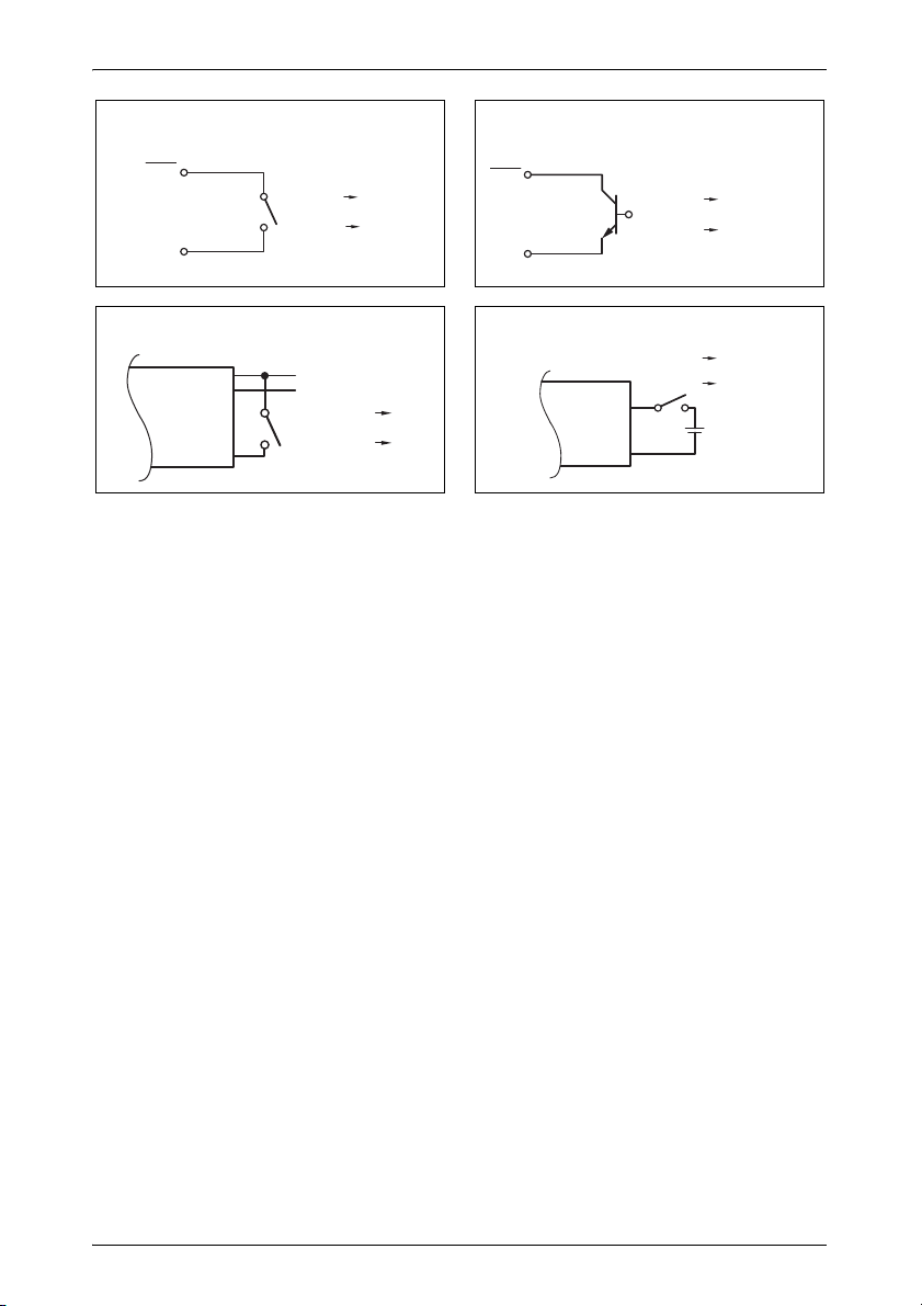
9.8 Connecting the external switch for turning on and
off
NOTE
I
You can use the following as an external switch:
external switch, voltage supply from the inverter: fig. 0, page 7
Control unit with relay or transistor circuit (TR): fig. a, page 7
external switch with voltage supply from the battery (BAT) of the vehicle:
fig. b, page 7
external switch with its own voltage supply (DC POWER) e.g. from the ig-
nition: fig. c, page 7
➤ Set the main switch (fig. 6 1, page 4 and fig. 7 1, page 5) to “OFF” and
make sure that the connection for the remote control (fig. 5 2, page 4) is
not assigned.
➤ Set the main switch (fig. 6 1, page 4 and fig. 7 1, page 5) to “RE-
MOTE”.
➤ Connect the external on/off switch with the connection cable to the termi-
nal (fig. 5 1, page 4).
Use cables with a cable cross section of 0.25 – 0.75 mm².
50
Page 51

EN
SinePower Connecting the inverter
9.9 Pin assignment
NOTE
I
The pins of the RS232 ports are assigned as follows:
Keep the cable lengths as short as possible (<10 m), so there is
no loss in the signal transmission.
Inverter Computer
Pin Description Description Pin
1 Not assigned Not assigned 1
2 GND RXD 2
3RXDTXD3
4TXDDTR4
5 Not assigned GND 5
6 Not assigned DSR 6
RTS 7
CTS 8
Not assigned 9
The pins of the RJ11 remote control connection are assigned as follows:
Inverter
Pin Description
1–
2GND
3RS232 RXD
4 RS232 TXD
5 RMT remote control
6 Not assigned
51
Page 52

EN
Using the inverter SinePower
10 Using the inverter
10.1 Switching on the inverter
➤ Set the main switch (fig. 6 1, page 4 and fig. 7 1, page 5) of the invert-
er to the “ON” position.
Set the On/Off switch to “OFF” to switch off.
➤ The inverter performs a self-test.
During the self-test, the built-in speaker emits tones and the LEDs flash.
✓ After the self-test is completed successfully, the “Input Level” (fig. 6 2,
page 4 and fig. 7 2, page 5) and “Load Status” (fig. 6 3, page 4 and
fig. 7 3, page 5) LEDs light up green.
Observe the following when using the device (see also chapter “Troubleshooting” on page 56)
The inverter switches off if:
the battery voltage drops below 10.5 V (12 Vg connection) or 21 V
(24 Vg connection),
the battery voltage exceeds 16 V (12 Vg connection) or 32 V (24 Vg
connection),
the inverter overheats.
➤ If this happens, shut down the inverter with the main switch(fig. 6 1,
page 4 and fig. 7 1, page 5).
➤ Check that the inverter is sufficiently ventilated and that the ventilation
grilles are unimpeded.
➤ Wait 5 – 10 minutes and switch the inverter on again without any electric
consumers.
When operating the inverter at high load for lengthy periods, it is advisable to
start the engine in order to recharge the vehicle battery.
52
Page 53

EN
SinePower Using the inverter
10.2 Status indications
“Input Level” LED(fig. 6 2, page 4 and fig. 7 2, page 5)
The “Input Level” LED shows the present range of the input voltage.
Display Input voltage
MSI912, MSI1312,
MSI1812, MSI 1812T
Red, slow flash <10.6 V <21.2 V
Red 10.6 – 11.0 V 21.2 – 22.0 V
Orange 11.0 – 12.0 V 22.0 – 24.0 V
Green 12.0 – 14.2 V 24.0 – 28.4 V
Orange, flash 14.2 – 15.0 V 28.4 – 30.0 V
Red, quick flash >15.0 >30.0
“Load Level” (fig. 6 3, page 4 and fig. 7 3, page 5)
The “Load Level” LED shows the power being supplied by the inverter.
Display Input voltage
MSI 912,
MSI924
Off 0 – 80 W 0 – 120 W 0 – 160 W
Green 80 – 320 W 120 – 480 W 160 – 640 W
Orange 320 – 720 W 480 – 1080 W 640 – 1440 W
Red, slow flash 720 – 800 W 1080 – 1200 W 1440 – 1600 W
Red, quick flash >800 W >1200 W >1600 W
MSI1312,
MSI1324
MSI924, MSI1324,
MSI1824, MSI1824T
MSI1812,
MSI1812T,
MSI1824,
MSI1824T
53
Page 54

EN
Using the inverter SinePower
10.3 Configuring the inverter
NOTE
I
You can adjust the device using the dip switch (fig. 6 4, page 4 and
fig. 7 4, page 5).
Setting the mains voltage
You can set the mains voltage using the S1 and S2 dip switches.
Setting the mains frequency
Settings can only be made using the dip switch if the S8 dip switch
is “On”.
Dip switch
Mains voltage S1 S2
200 V Off Off
220 V On Off
230 V Off On
240 V On On
WARNING! Danger of electrocution
!
You can set the mains frequency using the S3 dip switch.
54
Only adjust the S3 DIP switch when the respective frequency for
the output voltage should be used.
Dip switch
Net frequency S3
50 Hz Off
60 Hz On
Page 55

EN
SinePower Cleaning and caring for the inverter
Switching to energy-saving mode
You can set the energy-saving mode using the S4, S5 and S6 dip switches.
In this way, the battery you connect to the inverter is not discharged as quickly.
The inverter operates in energy-saving mode as long as the required power
is below the set level. If the required power exceeds the set level, the inverter
works in normal mode.
The values to be set on your inverter can be found in the following table:
Energy-saving mode Dip switch
MSI900 MSI1300 MSI1800 S4 S5 S6
Off Off Off Off Off Off
– <60 W <110 W On Off Off
<70 W <130 W <180 W On On Off
<200 W <210 W <220 W On On On
Defining settings
Using the S8 dip switch you can define whether the default settings or the
settings of dip switches S1-S7 are used.
Dip switch
Parameter S8
Default settings Off
Use dip switch S1-S7 On
11 Cleaning and caring for the inverter
NOTICE!
A
➤ Occasionally clean the product with a damp cloth.
Do not use sharp or hard objects or cleaning agents for cleaning
as these may damage the product.
55
Page 56

EN
Troubleshooting SinePower
12 Troubleshooting
WARNING!
!
I
The “Load Status” LED (fig. 6 3, page 4 and fig. 7 3,page 5) lights up red
to indicate the fault:
LED display Cause Remedy
Quick flash Input voltage is too high Check the input voltage and reduce
Slow flash Input voltage too low The battery needs recharging.
Occasional flash Overheating Switch off the inverter and the con-
Constantly lit Short circuit or reversed polar-
Do not open the device. You risk sustaining an electric shock by
doing this.
NOTE
If you have detailed questions on the specifications of the in-
verter please contact the manufacturer (addresses on the back of
the instruction manual).
it.
Check the cables and connections.
sumer.
Wait 5 to 10 minutes and switch the
inverter on again without any electric
consumers.
Reduce the load and make sure the
inverter has better ventilation. Then
switch the consumer back on.
Switch off the inverter and remove
ity
Excessive load
the consumer.
Then switch the inverter back on
without the consumer. If no excessive load is now shown, then there is
a short circuit in the consumer or the
total load was higher than the power
specified on the data sheet. MSI
1812T and MSI 1824T: The fuse in
the device must be pressed in again
by hand after it is triggered.
Check the cables and connections.
56
Page 57

EN
SinePower Warranty
13 Warranty
The statutory warranty period applies. If the product is defective, please
contact the manufacturer's branch in your country (see the back of the
instruction manual for the addresses) or your retailer.
For repair and guarantee processing, please include the following documents when you send in the device:
A copy of the receipt with purchasing date
A reason for the claim or description of the fault
14 Disposal
➤ Place the packaging material in the appropriate recycling waste bins
wherever possible.
If you wish to finally dispose of the product, ask your local recycling
centre or specialist dealer for details about how to do this in
M
accordance with the applicable disposal regulations.
57
Page 58

EN
Technical data SinePower
15 Technical data
NOTE
I
Item no.: 9102600111 9102600112
Rated input voltage: 12 V g 24 V g
Output power
at 25 °C for 10 min:
Peak output power: 1600 W
Output voltage: 200 – 240 Vw pure sine wave (THD < 3%)
Output frequency: 50 or 60 Hz
Idle current consumption: 1.8 A 1.0 A
Standby current consump-
tion:
Input voltage range: 10.5 V – 16 V 21 V – 32 V
Efficiency up to: 89 % 91 %
Ambient temperature for
operation:
Ambient temperature for
storage
Priority circuit: 230 V input protection: 10 A
Dimensions W x D x H: 197.5 x 94.3 x 291 mm, see fig. d, page 8
Weight: 4 kg
In the event of thermal overloading, the inverter reacts by reducing the power for temperatures of 40°C and above.
If the temperature exceeds 60°C, the inverter switches off.
MSI912 MSI924
900 W
0.5 A 0.3 A
-20 °C to 40 °C
40 °C to 60 °C (reduced power)
-30 °C to +70 °C
Switchover time of bypass relay: < 30 m sec
58
Page 59

EN
SinePower Technical data
MSI1312 MSI1324
Item no.: 9102600113 9102600114
Rated input voltage: 12 V g 24 V g
Output power
at 25 °C for 10 min:
Peak output power: 2400 W
Output voltage: 200 – 240 Vw pure sine wave (THD < 3%)
Output frequency: 50 or 60 Hz
Idle current consumption: 2.1 A 1.1 A
Standby current consump-
tion:
Input voltage range: 10.5 V – 16 V 21 V – 32 V
Efficiency up to: 90 % 91 %
Ambient temperature for
operation:
Ambient temperature for
storage
Priority circuit: 230 V input protection: 10 A
Dimensions W x D x H: 197.5 x 94.3 x 324.6 mm, see fig. d, page 8
Weight: 5 kg
0.5 A 0.3 A
40 °C to 60 °C (reduced power)
Switchover time of bypass relay: < 30 m sec
1300 W
-20 °C to 40 °C
-30 °C to +70 °C
59
Page 60

EN
Technical data SinePower
MSI1812 MSI1812T MSI1824 MSI 1824T
Item no.: 9102600115 9102600116 9102600117 9102600118
Rated input voltage: 12 V g 24 V g
Output power
at 25 °C for 10 min:
Peak output power: 3200 W
Output voltage: 200 – 240 Vw pure sine wave (THD < 3%)
Output frequency: 50 or 60 Hz
Idle current consumption: 2.1 A 1.1 A
Standby current consump-
tion:
Input voltage range: 10.5 V – 16 V 21 V – 32 V
Efficiency up to: 90 % 91 %
Bypass relay: – 25 A/277 Vw – 25 A/277 Vw
Ambient temperature for
operation:
Ambient temperature for
storage
Priority circuit: 230 V input protection: 10 A
Dimensions W x D x H: 197.5 x 94.3 x
376 mm
see fig. d,
page 8
Weight: 5.5 kg 6 kg 5.5 kg 6 kg
0.5 A 0.3 A
40 °C to 60 °C (reduced power)
Switchover time of bypass relay: < 30 m sec
197.5 x 94.3 x
see fig. d,
1800 W
-20 °C to 40 °C
-30 °C to +70 °C
406 mm
page 8
197.5 x 94.3 x
376 mm
see fig. d,
page 8
197.5 x 94.3 x
406 mm
see fig. d,
page 8
60
Page 61

EN
SinePower Technical data
E
Overvoltage shutdown
Device
MSI912, MSI1312,
MSI1812, MSI1812T
MSI924, MSI1324,
MSI1824, MSI1824T
Shutdown Restart
16 V 14.5 V
32 V 29 V
Overvoltage
Undervoltage shutdown
Device
MSI912, MSI1312,
MSI1812, MSI1812T
MSI924, MSI1324,
MSI1824, MSI1824T
Undervoltage
warning
11 V 10.5 V 12.5 V
22 V 21 V 25 V
Shutdown Restart
Undervoltage
Excess temperature shutdown
Internal temperature Temperature on cooling element
Shutdown Restart Shutdown Restart
60 °C 40 °C 95 °C <80 °C
Approvals
The device has E13 certification.
In compliance with the EMC directive 2004/108/EC including 2009/19/EC
and the Low-voltage Directive 2006/95/EC
EN55012: Class B
EN55014:Class B
EN61000-6-1/6-3: Class B
EN61000-6-2/6-4: Class A
EN61204-3
61
Page 62

FR
SinePower
Veuillez lire attentivement cette notice avant le montage et la mise en
service. Veuillez ensuite la conserver. En cas de passer le produit,
veuillez le transmettre au nouvel acquéreur.
Sommaire
1 Explication des symboles. . . . . . . . . . . . . . . . . . . . . . . . . . . . . . . . . 63
2 Consignes générales de sécurité. . . . . . . . . . . . . . . . . . . . . . . . . . . 63
3 Contenu de la livraison . . . . . . . . . . . . . . . . . . . . . . . . . . . . . . . . . . 66
4 Accessoires . . . . . . . . . . . . . . . . . . . . . . . . . . . . . . . . . . . . . . . . . . . 66
5 Groupe cible de cette notice . . . . . . . . . . . . . . . . . . . . . . . . . . . . . . 67
6 Usage conforme. . . . . . . . . . . . . . . . . . . . . . . . . . . . . . . . . . . . . . . . 67
7 Description technique . . . . . . . . . . . . . . . . . . . . . . . . . . . . . . . . . . . 68
8 Montage de l'onduleur . . . . . . . . . . . . . . . . . . . . . . . . . . . . . . . . . . . 72
9 Raccordement de l'onduleur . . . . . . . . . . . . . . . . . . . . . . . . . . . . . . 73
10 Utilisation de l'onduleur . . . . . . . . . . . . . . . . . . . . . . . . . . . . . . . . . . 79
11 Entretien et nettoyage de l'onduleur . . . . . . . . . . . . . . . . . . . . . . . . 83
12 Réparation des pannes . . . . . . . . . . . . . . . . . . . . . . . . . . . . . . . . . . 83
13 Garantie . . . . . . . . . . . . . . . . . . . . . . . . . . . . . . . . . . . . . . . . . . . . . . 84
14 Elimination . . . . . . . . . . . . . . . . . . . . . . . . . . . . . . . . . . . . . . . . . . . . 84
15 Caractéristiques techniques. . . . . . . . . . . . . . . . . . . . . . . . . . . . . . . 85
62
Page 63

FR
SinePower Explication des symboles
1 Explication des symboles
AVERTISSEMENT !
!
A
I
➤ Manipulation : ce symbole vous indique une action à effectuer. Les
manipulations à effectuer sont décrites étape par étape.
✓ Ce symbole décrit le résultat d’une manipulation.
Fig. 1 5, page 3 : cette information renvoie à un élément figurant sur une
illustration, dans cet exemple à la « position 5 de l'illustration 1 à la page 3 ».
Consigne de sécurité : le non-respect de ces consignes peut
entraîner la mort ou de graves blessures.
AVIS !
Le non-respect de ces consignes peut entraîner des dommages
matériels et des dysfonctionnements du produit.
REMARQUE
Informations complémentaires sur l'utilisation du produit.
2 Consignes générales de sécurité
2.1 Sécurité générale
Le fabricant décline toute responsabilité pour des dommages dans les cas
suivants :
des défauts de montage ou de raccordement
des influences mécaniques et des surtensions ayant endommagé le
matériel
des modifications apportées au produit sans autorisation explicite de la
part du fabricant
une utilisation différente de celle décrite dans la notice
63
Page 64

FR
Consignes générales de sécurité SinePower
AVERTISSEMENT !
!
Utilisez l'appareil conformément à l'usage pour lequel il a été
conçu.
N'utilisez pas l'appareil dans un environnement humide.
N'utilisez pas l'appareil à proximité de matériaux inflammables.
N'utilisez pas l'appareil dans un environnement explosif.
Seul un personnel qualifié et parfaitement informé des dangers
et règlements spécifiques à ces manipulations est habilité à effectuer les réparations et l'entretien.
Les personnes (y compris les enfants) qui ne sont pas en me-
sure d'utiliser le produit en toute sécurité — que ce soit en raison de déficiences physiques, sensorielles ou mentales ou bien
par manque d'expérience ou de connaissances — ne sont pas
autorisées à le faire sans surveillance.
Les appareils électriques ne sont pas des jouets pour
enfants !
Placez et utilisez l'appareil hors de leur portée.
2.2 Sécurité lors de l'installation de l'appareil
AVERTISSEMENT !
!
Seuls des artisans spécialisés, formés dans ce domaine et
connaissant les directives et les consignes de sécurité à appliquer sont habilités à procéder à l'installation de l'appareil.
Une mauvaise installation des appareils électriques sur des ba-
teaux peut entraîner des dommages dus à la corrosion au niveau du bateau. L'installation de l'appareil doit être effectuée
par un électricien spécialisé.
A
64
AVIS !
Veillez à un positionnement stable de l'appareil !
Veillez à installer et fixer l'appareil de manière à ce qu'il ne
puisse ni se renverser ni tomber.
N'exposez pas l'appareil à des sources de chaleur (rayonne-
ment solaire, chauffage, etc.). Vous éviterez ainsi une surchauffe supplémentaire de l'appareil.
Si des lignes électriques doivent traverser des cloisons en tôle
ou autres murs à arêtes vives, utilisez des tubes vides ou des
conduits pour câbles.
Page 65

FR
SinePower Consignes générales de sécurité
Ne faites pas passer de lignes électriques non fixées ou forte-
ment coudées sur des matériaux conducteurs (métal).
Ne tirez pas sur les lignes électriques.
Ne placez pas les câbles 230 V et la ligne de courant continu
12/24 V dans le même conduit (tube vide).
Fixez bien les lignes.
Posez les câbles de manière à exclure tout risque de trébuche-
ment ou d'endommagement du câble.
2.3 Consignes de sécurité concernant le fonctionnement de l'appareil
AVERTISSEMENT !
!
A
Faites fonctionner l'appareil uniquement si le boîtier et les
conduites sont intacts.
Certaines pièces de l'onduleur restent sous tension même
après le déclenchement du dispositif de sécurité (fusible).
Coupez l'alimentation électrique au cours de travaux sur l'appa-
reil.
AVIS !
Assurez-vous que les entrées et sorties d'air de l'appareil ne
sont pas couvertes.
Veillez à ce que l'aération soit suffisante. L'onduleur produit de
la chaleur qui doit pouvoir se dissiper librement.
Ne raccordez pas la sortie 230 V de l'onduleur (fig. 6 5, page 4
et fig. 7 5, page 5) à une autre source 230 V.
65
Page 66

FR
Contenu de la livraison SinePower
3 Contenu de la livraison
MSI900, MSI1300, MSI1800
Pos. dans
fig. 1,
page 3
1 Onduleur sinusoïdal
– Notice d'utilisation
MSI1800T
Pos. dans
fig. 2,
page 3
1 Onduleur sinusoïdal
2 Câble de raccordement à accouplement à contact de sécurité
3 Câble de raccordement à connecteur à contact de sécurité
– Notice d'utilisation
Désignation
Désignation
(pour sortie 230 Vw)
(pour alimentation 230 Vw)
4 Accessoires
Désignation N° de produit
Télécommande MCR-7
Télécommande MCR-9
66
Page 67

FR
SinePower Groupe cible de cette notice
5 Groupe cible de cette notice
Seuls des professionnels qualifiés, connaissant les directives et normes en
vigueur du pays dans lequel l'appareil est installé et utilisé, sont habilités à
effectuer l'installation électrique (chapitre « Raccordement de l'onduleur »,
page 73).
Tous les autres chapitres s'adressent également aux utilisateurs de l'appareil.
6 Usage conforme
AVERTISSEMENT !
!
Les onduleurs servent à transformer la tension continue de
12 Vg:
SinePower MSI912, n° de produit 9102600111
SinePower MSI1312, n° de produit 9102600113
SinePower MSI1812, n° de produit 9102600115
SinePower MSI1812T, n° de produit 9102600117
24 Vg:
SinePower MSI924, n° de produit 9102600112
SinePower MSI1324, n° de produit 9102600114
SinePower MSI1824, n° de produit 9102600116
SinePower MSI1824T, n° de produit 9102600118
L'onduleur ne doit pas être utilisé pour les véhicules dont le pôle
positif de la batterie est relié au châssis.
en une tension alternative 200 – 240 V de 50 Hz ou 60 Hz.
67
Page 68

FR
Description technique SinePower
7 Description technique
Les onduleurs peuvent être utilisés partout où
un raccordement 12 Vg (MSI912, MSI1312, MSI1812, MSI1812T)
un raccordement 24 Vg (MSI924, MSI1324, MSI1824, MSI1824T)
est disponible. Le faible poids et la construction compacte permettent de
monter cet appareil dans des camping-cars, véhicules utilitaires ou yachts à
moteur et à voile.
La tension de sortie correspond à la tension domestique de la prise (tension
sinusoïdale pure, THD < 3%).
Veuillez tenir compte des valeurs de puissance continue de sortie et de puissance de crête de sortie qui sont indiquées au chapitre « Caractéristiques
techniques », page 85. Les appareils nécessitant plus de puissance ne
doivent pas être raccordés.
REMARQUE
I
En cas de raccordement d'appareils avec un entraînement électrique (p. ex. perceuse, réfrigérateur, etc.), tenez compte du fait
que, pendant le démarrage, ces appareils nécessitent souvent
une puissance supérieure à celle indiquée sur la plaque signalétique.
L'onduleur possède différents mécanismes de protection :
Protection de surtension : l'onduleur s'éteint lorsque la valeur de ten-
sion passe au-dessus du seuil d'arrêt. Il redémarre lorsque la tension retombe à la valeur de redémarrage.
Protection de sous-tension : l'onduleur s'éteint lorsque la valeur de ten-
sion passe en dessous du seuil d'arrêt. Il redémarre lorsque la tension remonte à la valeur de redémarrage.
Protection de surtempérature : l'onduleur s'éteint lorsque la tempéra-
ture au sein de l'appareil ou la température au niveau du radiateur dépasse une valeur d'arrêt. Il redémarre lorsque la tension remonte à la
valeur de redémarrage.
Protection de surcharge : la LED de l'onduleur signale un dysfonction-
nement (lumière rouge permanente) lorsqu'une charge trop grande est
raccordée ou qu'un court-circuit s'est produit. Une fois que le fusible s'est
déclenché lors d'une surintensité, il doit être réinséré manuellement.
68
Page 69

FR
SinePower Description technique
Protection contre les inversions de polarité : la protection contre les
inversions de polarité empêche une inversion de la polarité lors du raccordement de l'onduleur.
Fusible de l'appareil (uniquement MSI 1812T et MSI 1824T) : la LED
de l'onduleur signale un dysfonctionnement (lumière rouge permanente).
Une fois que le fusible de l'appareil s'est déclenché, il doit être réinséré
manuellement.
REMARQUE
I
L'appareil peut de plus être configuré par interface RS232 à l'aide d'un ordinateur et des commutateurs DIP se trouvant sur l'appareil.
L'onduleur peut être commuté en mode d'économie d'énergie afin que la batterie raccordée ne se décharge pas trop rapidement.
Une télécommande (accessoire) permet de commander l'onduleur de manière confortable.
Les onduleurs SinePower MSI1812T et SinePower MSI1824T sont pourvus
d'un raccordement prioritaire 230 Vw. Si une tension externe de 230 Vw est
disponible, elle est utilisée en priorité. Si aucune tension externe de 230 Vw
n'est présente, la batterie raccordée est utilisée pour l'alimentation électrique.
Vous trouverez les valeurs seuil au chapitre « Caractéristiques
techniques », page 85.
69
Page 70

FR
Description technique SinePower
7.1 Eléments de commande
L'onduleur possède les raccords, affichages et éléments de commande suivants au dos de l'appareil :
Pos. dans
fig. 5,
page 4
1 Borne Réglage du fonctionnement par télécom-
2 Interface RS232,
3 POS+ Borne positive
4 NEG– Borne négative
5 Borne de masse Mise à la terre à la carrosserie du véhicule
MSI900, MSI 1300, MSI 1800
L'onduleur possède les raccords, affichages et éléments de commande suivants sur la face avant de l'appareil :
Pos. dans
fig. 6,
page 4
Désignation Description
mande
Raccordement d'un PC via un port série
port REMOTE
Désignation Description
RS232 ou raccordement de la télécommande MCR-7, MCR-9
1 Interrupteur prin-
cipal
« ON/OFF/
REMOTE »
2 LED « Input
Level »
3 LED « Load
Level »
4 Commutateur
DIP
5 Prise Schuko Sortie 230 V
70
Permet d'allumer, d'éteindre l'appareil ou
de le faire fonctionner à l'aide de la télécommande (accessoire)
Indique la plage de tension d'entrée
Indique la plage de puissance émise par
l'onduleur
Permet de procéder à des réglages de
l'onduleur (p. ex. tension du secteur, fréquence du réseau, mode d'économie
d'énergie)
Page 71

FR
SinePower Description technique
MSI 1800T
L'onduleur possède les raccords, affichages et éléments de commande suivants sur la face avant de l'appareil :
Pos. dans
fig. 7,
page 5
Désignation Description
1 Interrupteur prin-
cipal
« ON/OFF/
REMOTE »
2 LED « Input
Level »
3 LED « Load
Level »
4 Commutateur
DIP
5 AC Output Sortie 230 V
6 AC Input Entrée 230 V
7 Fusible Protège l'onduleur de la surcharge.
8 Vis de mise à la
terre
Permet d'allumer, d'éteindre l'appareil ou
de le faire fonctionner à l'aide de la télécommande (accessoire)
Indique la plage de tension d'entrée
Indique la plage de puissance émise par
l'onduleur
Permet de procéder à des réglages de
l'onduleur (p. ex. tension du secteur, fréquence du réseau, mode d'économie
d'énergie)
Il est possible d'appuyer de nouveau sur
le fusible une fois qu'il s'est déclenché.
Mise à la terre ou coupure de mise à la
terre
71
Page 72

FR
Montage de l'onduleur SinePower
8 Montage de l'onduleur
8.1 Outils nécessaires
Pour le raccordement électrique, vous devez disposer des outils suivants :
Pince de sertissage
3 câbles de raccordement flexibles de différentes couleurs. Vous trouve-
rez la section nécessaire dans le tableau du chapitre « Raccordement de
l'onduleur », page 73.
Cosses de câble et embouts
Pour la fixation de l'onduleur, vous devez disposer des aides de montage suivantes :
Vis d'assemblage (M4) à rondelles et écrous de protection ou
Vis à tôle ou à bois.
8.2 Instructions de montage
Lisez attentivement les remarques suivantes lors du choix du lieu
d'installation :
Le montage de l'onduleur peut être horizontal ou vertical.
L'onduleur doit être monté à un endroit protégé de l'humidité.
L'onduleur ne doit pas être monté dans des environnements contenant
des matériaux inflammables.
L'onduleur ne doit pas être monté dans des environnements poussiéreux.
Le lieu de montage doit être bien aéré. En cas d'installations dans de pe-
tits locaux fermés, ceux-ci doivent disposer d'un système d'aération et de
ventilation. La distance libre minimale autour de l'onduleur doit être d'au
moins 25 cm (fig. 3, page 3).
L'arrivée d'air sur la partie inférieure et la sortie d'air à l'arrière de l'ondu-
leur doivent rester libres.
En cas de températures ambiantes supérieures à 40°C (p. ex. dans les
compartiments moteur ou chauffage, en cas de rayonnement direct du
soleil), il est possible que se produise un arrêt automatique en raison de
l'échauffement propre de l'onduleur en cas de charge.
La surface de montage doit être plane et présenter une stabilité suffi-
sante.
72
Page 73

FR
SinePower Raccordement de l'onduleur
AVIS !
A
Avant de commencer à effectuer des perçages, assurez-vous
qu'aucun câble électrique ou autre élément du véhicule ne risque
d'être endommagé par le perçage, le sciage ou le limage.
8.3 Montage de l'onduleur
➤ Maintenez l'onduleur à l'endroit que vous avez choisi pour le montage et
marquez les points de fixation (fig. 4 A, page 4).
➤ Fixez l'onduleur selon la méthode de fixation que vous avez choisie
(fig. 4 B, page 4).
9 Raccordement de l'onduleur
9.1 Consignes générales
AVERTISSEMENT !
!
Seule une entreprise spécialisée possédant le savoir-faire né-
cessaire est habilitée à effectuer le raccordement de l'onduleur. Les informations suivantes sont destinées à un personnel
qualifié, informé des directives et des consignes de sécurité à
appliquer.
L'onduleur ne doit pas être utilisé pour les véhicules dont le
pôle positif de la batterie est relié au châssis.
Si vous ne placez aucun fusible dans la ligne positive, les
lignes peuvent être surchargées, et cela peut provoquer un incendie.
Une inversion de polarité peut entraîner la destruction de l'on-
duleur.
MSI900, MSI1300, MSI1800 : L'onduleur ne doit pas être uti-
lisé dans un réseau à lignes en boucle, mais uniquement pour
alimenter en courant des appareils isolés. Ces appareils
doivent être enfichés directement dans l'onduleur ou être raccordés à l'onduleur à l'aide d'un câble de rallonge fabriqué à
cet effet et gainé.
En cas d'installations dans les véhicules ou les bateaux, l'onduleur doit
être relié au châssis ou à la masse.
73
Page 74

FR
Raccordement de l'onduleur SinePower
Lors de la construction d'un circuit de répartiteurs de prises (construction
de réseau), respectez les directives en vigueur.
Utilisez exclusivement des câbles de cuivre.
Les câbles doivent être aussi courts que possible (< 1,8 m).
Respectez le diamètre de câble nécessaire et placez un fusible de ligne
(fig. 8 3, page 5) aussi près que possible de la batterie dans la ligne positive (voir tableau).
Appareil
MSI912 25 mm² 115 A
MSI924 25 mm² 75 A
MSI1312 35 mm² 170 A
MSI1324 35 mm² 85 A
MSI1812/MSI1812T 35 mm² 228 A
MSI1824/MSI1824T 35 mm² 115 A
Diamètre de câble
nécessaire
Fusible de ligne
(fig. 8 3, page 5)
9.2 Raccordement de l'onduleur à une batterie
REMARQUE
I
➤ Placez le commutateur principal (fig. 6 1, page 4 et fig. 7 1, page 5)
sur « OFF ».
➤ Dévissez la vis (fig. 8 1, page 5) de la borne rouge positive (fig. 8 2,
page 5).
➤ Faites glisser la cosse de câble (fig. 8 2, page 5) du câble positif dans
la borne positive rouge et fixez-la avec la vis.
Vissez les vis ou les écrous avec un couple de serrage de 12 –
13 Nm. Si les vis sont mal serrées, cela peut provoquer des surchauffes.
➤ Raccordez de même le câble négatif à la borne négative noire (fig. 8 4,
page 5).
➤ Montez le câble positif de l'onduleur au pôle positif de la batterie du véhi-
cule et raccordez-le.
➤ Montez le câble négatif de l'onduleur au pôle négatif de la batterie du vé-
hicule et raccordez-le.
➤ Raccordez la borne de masse à la carrosserie du véhicule.
74
Page 75

FR
SinePower Raccordement de l'onduleur
9.3 Raccordement d'une ligne d'alimentation 230 V
(uniquement MSI1800T)
➤ Enfichez le câble de raccordement 230 Vw à connecteur à contact de sé-
curité dans la douille d'entrée 230 Vw (fig. 7 6, page 5).
➤ Raccordez la prise à contact de sécurité au courant alternatif 230 V.
9.4 Raccordement de la ligne de sortie 230 V
(uniquement MSI1800T)
AVERTISSEMENT !
!
➤ Enfichez le câble de raccordement 230 Vw à accouplement à contact de
sécurité dans la douille de sortie 230 Vw (fig. 7 5, page 5).
Avant le raccordement de la ligne de sortie à 230 V, assurez-vous
que le commutateur principal est éteint.
9.5 Raccordement de plusieurs consommateurs
(uniquement MSI1800T)
A la livraison, l'appareil est équipé d'une séparation galvanique. Afin d'exploiter plusieurs consommateurs en toute sécurité, le montage d'un disjoncteur
dans le circuit de bloc multiprise est indispensable ; cf. exemple de schéma :
fig. 8, page 5.
Légende de l'exemple de schéma du circuit :
Pos.
dans
fig. 8,
page 5
1 Source d'entrée 230 Vw
2 Autres appareils : chargeur de batterie, réfrigérateur etc.
3 Source de tension CC (batterie)
4 Onduleur
5 Cavaliers de mise à la terre en place (ne sont pas en place à la
6 Disjoncteur
7 Circuit de bloc multiprise pour consommateur d'énergie
Explication
livraison et hachurés)
75
Page 76

FR
Raccordement de l'onduleur SinePower
AVERTISSEMENT Danger de mort par électrocution
!
➤ Montez un disjoncteur dans le circuit de bloc multiprise.
9.6 Placement des cavaliers de mise à la terre
➤ Dévissez la vis de mise à la terre de l'alésage inférieur.
➤ Vissez la vis dans l'alésage supérieur.
9.7 Raccordement de la télécommande MCR-7 ou
A
Si vous souhaitez raccorder plus d'un consommateur à l'onduleur
et montez pour ce faire un circuit de bloc multiprise, vous devez
prévoir un disjoncteur et monter les cavaliers de mise à la terre
dans l'onduleur.
(fig. 5 4, page 4)
MCR-9 (en accessoire)
REMARQUE!
Ne branchez le raccordement de la télécommande qu'au port
remote. Un raccordement incorrect risque d'endommager l'appareil.
Assurez-vous que la télécommande et l'onduleur sont alimen-
tés avec la même valeur de tension d'entrée.
Tenez compte du manuel de la télécommande.
➤ Raccordez la télécommande (en accessoire) au port remote (fig. 5 2,
page 4).
76
Page 77

FR
SinePower Raccordement de l'onduleur
9.8 Raccordement d'un commutateur externe pour la
mise en marche et à l'arrêt
REMARQUE
I
Vous pouvez utiliser les dispositifs suivants comme commutateur externe :
interrupteur externe, alimentation en tension par l'onduleur : fig. 0,
page 7
unité de commande avec câblage relais ou transistor : fig. a, page 7
interrupteur externe avec alimentation en tension par la batterie du véhi-
cule : fig. b, page 7
interrupteur externe avec alimentation en tension propre (DC POWER),
p. ex. de l'allumage : fig. c, page 7
➤ Placez le commutateur principal (fig. 6 1, page 4 et fig. 7 1, page 5)
sur « OFF » et assurez-vous que le raccordement pour la télécommande
(fig. 5 2, page 4) n'est pas occupé.
➤ Placez le commutateur principal (fig. 6 1, page 4 et fig. 7 1, page 5)
sur la position « REMOTE ».
➤ Raccordez le commutateur externe de marche et d'arrêt à la borne
(fig. 5 1, page 4) à l'aide du câble de raccordement.
Utilisez des câbles d'une section de 0,25 – 0,75 mm².
77
Page 78

FR
Raccordement de l'onduleur SinePower
9.9 Affectations des broches
REMARQUE
I
Les broches du port RS232 sont affectées comme suit :
Utilisez des longueurs de câbles les plus courtes possible
(< 10 m) afin d'éviter les pertes de transmission de signaux.
Onduleurs Ordinateur
Broche Description Description Broche
1 Non occupé Non occupé 1
2 GND RXD 2
3RXDTXD3
4TXDDTR4
5 Non occupé GND 5
6 Non occupé DSR 6
RTS 7
CTS 8
Non occupé 9
Les broches du raccordement RJ11 pour la télécommande sont affectées
comme suit :
Onduleurs
Broche Description
1–
2GND
3RS232 RXD
4 RS232 TXD
5 Télécommande RMT
6 Non occupé
78
Page 79

FR
SinePower Utilisation de l'onduleur
10 Utilisation de l'onduleur
10.1 Mise en service de l'onduleur
➤ Placez le commutateur principal (fig. 6 1, page 4 et fig. 7 1, page 5) de
l'onduleur en position « ON ».
Pour éteindre, placez le commutateur de marche/arrêt sur « OFF ».
➤ L'onduleur procède à un test automatique.
Pendant l'auto-diagnostic, le haut-parleur interne émet des sons et les
DEL clignotent.
✓ Une fois l'autotest terminé, les LED « Input Level » (fig. 6 2, page 4 et
fig. 7 2, page 5) et « Load Status » (fig. 6 3, page 4 et fig. 7 3,
page 5) s'allument en vert.
Veuillez respecter les indications suivantes lors de l'utilisation (voir également le chapitre « Réparation des pannes », page 83)
L'onduleur s'éteint si
la tension de la batterie chute en dessous de 10,5 V (raccordement
12 Vg) ou 21 V (raccordement 24 Vg),
la tension de la batterie dépasse 16 V (raccordement 12 Vg) ou 32 V
(raccordement 24 Vg),
l'onduleur est surchauffé.
➤ Dans ce cas, désactivez l'onduleur à l'aide du commutateur principal
(fig. 6 1, page 4 et fig. 7 1, page 5).
➤ Vérifiez que l'onduleur est assez ventilé et que les ouvertures d'aération
et fentes de ventilation sont libres.
➤ Attendez env. 5 – 10 min et allumez de nouveau l'onduleur sans consom-
mateur.
Lors de l'utilisation de l'onduleur pendant une longue période et avec une
charge importante, il est conseillé de démarrer le moteur afin de recharger la
batterie du véhicule.
79
Page 80

FR
Utilisation de l'onduleur SinePower
10.2 Témoins lumineux de fonctionnement
LED « Input Level » (fig. 6 2, page 4 et fig. 7 2, page 5)
La LED « Input Level » indique la plage de tension dans laquelle se trouve la
tension d'entrée.
Affichage Tension d'entrée
MSI912, MSI1312,
MSI1812, MSI 1812T
Clignotement rouge lent <10,6 V <21,2 V
Rouge 10,6 – 11,0 V 21,2 – 22,0 V
Orange 11,0 – 12,0 V 22,0 – 24,0 V
Vert 12,0 – 14,2 V 24,0 – 48,4 V
Clignotement orange 14,2 – 15,0 V 48,4 – 30,0 V
Clignotement rouge
rapide
LED « Load Level » (fig. 6 3, page 4 et fig. 7 3, page 5)
La LED « Load Level » indique la plage de puissance émise par l'onduleur.
Affichage Tension d'entrée
MSI 912,
MSI924
désactivé 0 – 80 W 0 – 120 W 0 – 160 W
Vert 80 – 320 W 120 – 480 W 160 – 640 W
Orange 320 – 720 W 480 – 1080 W 640 – 1440 W
Clignotement rouge lent 720 – 800 W 1080 – 1200 W 1440 – 1600 W
Clignotement rouge
rapide
>15,0 >30,0
MSI1312,
MSI1324
>800 W >1200 W >1600 W
MSI924, MSI1324,
MSI1824, MSI1824T
MSI1812,
MSI1812T,
MSI1824,
MSI1824T
80
Page 81

FR
SinePower Utilisation de l'onduleur
10.3 Réglage de l'onduleur
REMARQUE
I
Vous pouvez ajuster l'appareil à l'aide du commutateur DIP (fig. 6 4, page 4
et fig. 7 4, page 5).
Réglage de la tension du secteur
Vous pouvez régler la tension du secteur à l'aide des commutateurs DIP S1
et S2.
Tension du secteur S1 S2
Les réglages via le commutateur DIP ne sont repris que si le commutateur DIP S8 se trouve en position « Marche ».
Commutateur DIP
200 V désactivé désactivé
220 V activé désactivé
230 V désactivé activé
240 V activé activé
Réglage de la fréquence du secteur
AVERTISSEMENT ! Danger de mort par électrocution !
!
Le commutateur DIP S3 vous permet de régler la fréquence du réseau.
Fréquence du réseau S3
Changez la position du commutateur DIP S3 uniquement si vous
devez utiliser la fréquence correspondante pour la tension de sortie.
Commutateur DIP
50 Hz désactivé
60 Hz activé
81
Page 82

FR
Utilisation de l'onduleur SinePower
Réglage du mode d'économie d'énergie
Les commutateurs DIP S4, S5 et S6 vous permettent de régler le mode
d'économie d'énergie. Ainsi, la batterie à laquelle l'onduleur est raccordé ne
se décharge pas aussi rapidement.
L'onduleur fonctionne en mode d'économie d'énergie tant que la puissance
nécessaire se trouve en dessous de la valeur de puissance réglée. Si la puissance nécessaire se trouve au-dessus de la valeur de puissance réglée, l'onduleur fonctionne normalement.
Les valeurs à régler pour l'onduleur sont présentées dans le tableau suivant :
Mode économie d'énergie Commutateur DIP
MSI900 MSI1300 MSI1800 S4 S5 S6
désactivé désactivé désactivé désactivé désactivé désactivé
– <60 W <110 W activé désactivé désactivé
<70 W <130 W <180 W activé activé désactivé
<200 W <210 W <220 W activé activé activé
Détermination des réglages
Le commutateur DIP S8 vous permet de déterminer si les réglages d'origine
ou les réglages des les commutateurs DIP S1-S1 sont utilisés.
Commutateur DIP
Paramètre S8
Réglages d'origine désactivé
Utiliser commutateur DIP S1-S7 activé
82
Page 83

FR
SinePower Entretien et nettoyage de l'onduleur
11 Entretien et nettoyage de l'onduleur
AVIS !
A
➤ Nettoyez le produit avec un tissu humide.
N’utilisez aucun objet coupant ou dur, ni de détergents pour le
nettoyage. Cela pourrait endommager le produit.
12 Réparation des pannes
AVERTISSEMENT !
!
I
La LED « Load Status » (fig. 6 3, page 4 et fig. 7 3, page 5) indique la
panne en rouge :
N'ouvrez pas l'appareil. Vous vous exposez à un risque
d'électrocution !
REMARQUE
En cas de questions sur les caractéristiques de l'onduleur,
veuillez vous adresser au fabricant (adresses au dos de la notice).
Affichage DEL Cause Solution
Clignotement rapide Tension d'entrée trop élevée. Vérifiez la tension d'entrée et rédui-
sez-la.
Clignotement lent Tension d'entrée trop faible. La batterie doit être rechargée.
Vérifiez les lignes et les connexions.
Clignotement intermittent
Surcharge thermique Eteignez l'onduleur et le consomma-
teur.
Attendez env. 5 – 10 minutes et allu-
mez de nouveau l'onduleur sans
consommateur.
Réduisez la charge et assurez-vous
que l'onduleur est mieux aéré.
Remettez alors le consommateur en
marche.
83
Page 84

FR
Garantie SinePower
Affichage DEL Cause Solution
Eclairage permanent Court-circuit ou inversion des
pôles
Surcharge
Eteignez l'onduleur et retirez le
consommateur.
Remettez alors l'onduleur en
marche, sans le consommateur. Si
aucune surcharge n'est plus affichée, il existe un court-circuit au
niveau du consommateur ou la
charge totale était supérieure à la
puissance spécifiée dans la fiche
technique. MSI 1812T et MSI
1824T : Une fois que le fusible de
l'appareil s'est déclenché, il doit être
réinséré manuellement.
Vérifiez les lignes et les connexions.
13 Garantie
Le délai légal de garantie s'applique. Si le produit s'avérait défectueux, veuillez vous adresser à la filiale du fabricant située dans votre pays (voir
adresses au verso du présent manuel) ou à votre revendeur spécialisé.
Veuillez y joindre les documents suivants pour la gestion des réparations et
de la garantie :
une copie de la facture avec la date d'achat,
le motif de la réclamation ou une description du dysfonctionnement.
14 Elimination
➤ Jetez les emballages dans les conteneurs de déchets recyclables prévus
à cet effet.
Lorsque vous mettrez votre produit définitivement hors service,
informez-vous auprès du centre de recyclage le plus proche ou
M
84
auprès de votre revendeur spécialisé sur les prescriptions relatives
au retraitement des déchets.
Page 85

FR
SinePower Caractéristiques techniques
15 Caractéristiques techniques
REMARQUE
I
N° de produit : 9102600111 9102600112
Tension nominale d'entrée : 12 Vg 24 Vg
Puissance de sortie à 25 °C
pendant 10 minutes :
Puissance de sortie en
crête :
Tension de sortie : 200 – 240 Vw onde sinusoïdale pure (THD < 3%)
Fréquence de sortie : 50 ou 60 Hz
Intensité absorbée à vide : 1,8 A 1,0 A
Intensité absorbée en veille : 0,5 A 0,3 A
Plage de tension d'entrée : 10,5 V – 16 V 21 V – 32 V
Rendement jusqu'à : 89 % 91 %
Température ambiante de
fonctionnement :
Température ambiante de
stockage :
Raccordement prioritaire : 230 V Fusible d'entrée : 10 A
Dimensions l x p x h : 197,5 x 94,3 x 291 mm, voir fig. d, page 8
Poids : 4 kg
En cas de surcharge thermique, l'onduleur réagit et réduit sa puissance en cas de température supérieure à 40 °C.
En cas de température supérieure à 60 °C, l'onduleur s'éteint.
MSI912 MSI 924
900 W
1600 W
-20 °C à 40 °C
40 °C à 60 °C (puissance réduite)
-30 °C à +70 °C
Temps de commutation relais bypass : < 30 m sec
85
Page 86

FR
Caractéristiques techniques SinePower
MSI1312 MSI1324
N° de produit : 9102600113 9102600114
Tension nominale d'entrée : 12 Vg 24 Vg
Puissance de sortie à 25 °C
pendant 10 minutes :
Puissance de sortie en
crête :
Tension de sortie : 200 – 240 Vw onde sinusoïdale pure (THD < 3%)
Fréquence de sortie : 50 ou 60 Hz
Intensité absorbée à vide : 2,1 A 1,1 A
Intensité absorbée en veille : 0,5 A 0,3 A
Plage de tension d'entrée : 10,5 V – 16 V 21 V – 32 V
Rendement jusqu'à : 90 % 91 %
Température ambiante de
fonctionnement :
Température ambiante de
stockage :
Raccordement prioritaire : 230 V Fusible d'entrée : 10 A
Dimensions l x p x h : 197,5 x 94,3 x 324,6 mm, voir fig. d, page 8
Poids : 5 kg
40 °C à 60 °C (puissance réduite)
Temps de commutation relais bypass : < 30 m sec
1300 W
2400 W
-20 °C à 40 °C
-30 °C à +70 °C
86
Page 87

FR
SinePower Caractéristiques techniques
MSI1812 MSI1812T MSI1824 MSI 1824T
N° de produit : 9102600115 9102600117 9102600116 9102600118
Tension nominale d'entrée : 12 Vg 24 Vg
Puissance de sortie à 25 °C
pendant 10 minutes :
Puissance de sortie en
crête :
Tension de sortie : 200 – 240 Vw onde sinusoïdale pure (THD < 3%)
Fréquence de sortie : 50 ou 60 Hz
Intensité absorbée à vide : 2,1 A 1,1 A
Intensité absorbée en
veille :
Plage de tension d'entrée : 10,5 V – 16 V 21 V – 32 V
Rendement jusqu'à : 90 % 91 %
Relais de pontage : – 25 A/277 Vw – 25 A/277 Vw
Température ambiante de
fonctionnement :
Température ambiante de
stockage :
Raccordement prioritaire : 230 V Fusible d'entrée : 10 A
Dimensions l x p x h : 197,5 x 94,3 x
376 mm
voir fig. d,
page 8
Poids : 5,5 kg 6 kg 5,5 kg 6 kg
0,5 A 0,3 A
40 °C à 60 °C (puissance réduite)
Temps de commutation relais bypass : < 30 m sec
197,5 x 94,3 x
voir fig. d,
1800 W
3200 W
-20 °C à 40 °C
-30 °C à +70 °C
406 mm
page 8
197,5 x 94,3 x
376 mm
voir fig. d,
page 8
197,5 x 94,3 x
406 mm
voir fig. d,
page 8
87
Page 88

FR
Caractéristiques techniques SinePower
E
Protection de surtension
Appareil
MSI912, MSI1312,
MSI1812, MSI1812T
MSI924, MSI1324,
MSI1824, MSI1824T
Protection de sous-tension
Appareil
MSI912, MSI1312,
MSI1812, MSI1812T
MSI924, MSI1324,
MSI1824, MSI1824T
Avertissement de
sous-tension
Protection de surtempérature
Température interne Température au niveau du radiateur
Arrêt Redémarrage Arrêt Redémarrage
60 °C 40 °C 95 °C <80 °C
Surtension
Arrêt Redémarrage
16 V 14,5 V
32 V 29 V
Sous-tension
Arrêt Redémarrage
11 V 10,5 V 12,5 V
22 V 21 V 25 V
Certifications
Cet appareil possède la certification E13.
Conformément à la directive CEM 2004/108/CE, 2009/19/CE incluse, et la
directive basse tension 2006/95/CE
EN55012 : Classe B
EN55014 : Classe B
EN61000-6-1/6-3 : Classe B
EN61000-6-2/6-4 : Classe A
EN61204-3
88
Page 89

ES
SinePower
Lea detenidamente estas instrucciones antes de llevar a cabo la instalación y puesta en funcionamiento, y consérvelas en un lugar seguro.
En caso de vender o entregar el producto a otra persona, entregue
también estas instrucciones.
Índice
1 Aclaración de los símbolos . . . . . . . . . . . . . . . . . . . . . . . . . . . . . . . 90
2 Indicaciones generales de seguridad . . . . . . . . . . . . . . . . . . . . . . . 90
3 Volumen de entrega. . . . . . . . . . . . . . . . . . . . . . . . . . . . . . . . . . . . . 93
4 Accesorios . . . . . . . . . . . . . . . . . . . . . . . . . . . . . . . . . . . . . . . . . . . . 93
5 Destinatarios de estas instrucciones . . . . . . . . . . . . . . . . . . . . . . . . 94
6 Uso adecuado . . . . . . . . . . . . . . . . . . . . . . . . . . . . . . . . . . . . . . . . . 94
7 Descripción técnica . . . . . . . . . . . . . . . . . . . . . . . . . . . . . . . . . . . . . 95
8 Montar el inversor . . . . . . . . . . . . . . . . . . . . . . . . . . . . . . . . . . . . . . 99
9 Conectar el inversor. . . . . . . . . . . . . . . . . . . . . . . . . . . . . . . . . . . . 100
10 Usar el inversor . . . . . . . . . . . . . . . . . . . . . . . . . . . . . . . . . . . . . . . 106
11 Mantenimiento y limpieza del inversor. . . . . . . . . . . . . . . . . . . . . . 109
12 Solución de fallos. . . . . . . . . . . . . . . . . . . . . . . . . . . . . . . . . . . . . . 110
13 Garantía legal . . . . . . . . . . . . . . . . . . . . . . . . . . . . . . . . . . . . . . . . 111
14 Gestión de residuos . . . . . . . . . . . . . . . . . . . . . . . . . . . . . . . . . . . . 111
15 Datos técnicos . . . . . . . . . . . . . . . . . . . . . . . . . . . . . . . . . . . . . . . . 112
89
Page 90

ES
Aclaración de los símbolos SinePower
1 Aclaración de los símbolos
¡ADVERTENCIA!
!
A
I
➤ Paso a seguir: este símbolo le indica que debe realizar un paso. Todos
los procedimientos necesarios se describen paso a paso.
✓ Este símbolo describe el resultado de un paso realizado.
Fig. 1 5, página 3: esta indicación hace referencia a un elemento de una
figura, en este ejemplo a la “Posición 5 en la figura 1 de la página 3”.
Indicación de seguridad: su incumplimiento puede acarrear la
muerte o graves lesiones.
¡AVISO!
Su incumplimiento puede acarrear daños materiales y perjudicar
el correcto funcionamiento del producto.
NOTA
Información adicional para el manejo del producto.
2 Indicaciones generales de seguridad
2.1 Seguridad general
El fabricante declina toda responsabilidad ante daños ocurridos en los
siguientes casos:
errores de montaje o de conexión,
daños en el producto debido a influencias mecánicas y sobretensiones
modificaciones realizadas en el producto sin el expreso consentimiento
del fabricante
utilización del aparato para fines distintos a los descritos en las instruc-
ciones.
90
Page 91

ES
SinePower Indicaciones generales de seguridad
¡ADVERTENCIA!
!
Utilice el aparato sólo para aquellos fines para los que ha sido
concebido.
No ponga en funcionamiento el aparato en ambientes húmedos
o en contacto con líquidos.
No ponga en funcionamiento el aparato en las cercanías de
sustancias combustibles.
No ponga en funcionamiento el aparato en zonas con riesgos
de explosión.
El mantenimiento y reparación sólo lo puede llevar a cabo per-
sonal especializado y familiarizado con los riesgos y normas
pertinentes.
Las personas (incluidos los niños) que, debido a sus capacida-
des físicas, sensoriales o mentales, a su falta de experiencia o
a desconocimiento, no pueden utilizar el producto de forma segura, no tienen permitido utilizar este producto sin la vigilancia
y las instrucciones de una persona sobre la que recae tal responsabilidad.
Los aparatos eléctricos no son juguetes.
Mantenga y utilice el aparato fuera del alcance de los niños.
2.2 Seguridad en la instalación del aparato
¡ADVERTENCIA!
!
A
La instalación del aparato sólo la puede realizar personal técni-
co debidamente cualificado y familiarizado con las directivas y
normativas de seguridad que se han de aplicar.
Una instalación incorrecta de aparatos eléctricos en embarca-
ciones puede producir daños de corrosión en la embarcación.
La instalación del aparato debe ser realizada por un electricista
especializado (en embarcaciones).
¡AVISO!
¡Procure mantenerlo en una posición segura!
Instale y fije el aparato de forma segura, de manera que no pueda caerse ni volcarse.
No exponga el aparato a fuentes de calor (radiación directa del
sol, calefacción, etc.). De este modo, evitará un calentamiento
adicional del aparato.
91
Page 92

ES
Indicaciones generales de seguridad SinePower
Si los cables deben pasar a través de paredes de chapa o de
otro tipo de paredes con bordes afilados, utilice tubos corrugados o guías de cable.
Los cables no deben quedar sueltos ni muy doblados al colo-
carlos en materiales conductores de electricidad (metales).
No tire de los cables.
No tienda el cable de red de 230 V y cable de corriente continua
de 12/24 V en el mismo canal de cableado (tubo corrugado).
Fije bien los cables.
Tienda los cables de tal forma que no se pueda tropezar con
ellos ni se pueda dañar el cable.
2.3 Seguridad durante el funcionamiento del aparato
¡ADVERTENCIA!
!
Utilice el aparato sólo cuando la carcasa y los cables no presen-
ten daños.
Algunas piezas del inversor siguen teniendo tensión incluso
después de que haya saltado el dispositivo de protección (fusible).
Siempre que realice tareas en el aparato desconecte la alimen-
tación de corriente.
A
92
¡AVISO!
Asegúrese de que las entradas y salidas de aire del aparato no
queden tapadas.
Preste atención a que haya una buena ventilación. El inversor
produce calor residual que se debe evacuar.
No conecte la salida de 230 V del convertidor (fig. 6 5,
página 4 y fig. 7 5, página 5) con otra fuente de tensión de
230 V.
Page 93

ES
SinePower Volumen de entrega
3 Volumen de entrega
MSI900, MSI1300, MSI1800
Pos. en
fig. 1,
página 3
1 Inversor senoidal
– Instrucciones de uso
MSI1800T
Pos. en
fig. 2,
página 3
1 Inversor senoidal
2 Cable de conexión con conexión de seguridad (para salida de
3 Cable de conexión con enchufe de seguridad (para alimenta-
– Instrucciones de uso
Denominación
Denominación
230 Vw)
ción de 230 Vw)
4 Accesorios
Denominación N.° art.
Control remoto MCR-7
Control remoto MCR-9
93
Page 94

ES
Destinatarios de estas instrucciones SinePower
5 Destinatarios de estas instrucciones
La instalación eléctrica (capítulo “Conectar el inversor” en la página 100)
solo pueden realizarla operarios especializados que conozcan las directivas
y normativas vigentes en el país donde se instale o utilice el aparato.
El resto de los capítulos van también dirigidos a los usuarios del aparato.
6 Uso adecuado
¡ADVERTENCIA!
!
Los convertidores tienen la función de transformar la tensión continua de
12 Vg:
SinePower MSI912, n° art. 9102600111
SinePower MSI1312, n° art. 9102600113
SinePower MSI1812, n° art. 9102600115
SinePower MSI1812T, n° art. 9102600117
24 Vg:
SinePower MSI924, n° art. 9102600112
SinePower MSI1324, n° art. 9102600114
SinePower MSI1824, n° art. 9102600116
SinePower MSI1824T, n° art. 9102600118
El inversor no se puede usar en vehículos cuyo polo positivo de
la batería esté conectado al chasis.
en una tensión alterna de 200 – 240 V de 50 Hz o 60 Hz.
94
Page 95

ES
SinePower Descripción técnica
7 Descripción técnica
El inversor se puede usar en todos los lugares donde esté disponible:
una conexión de 12-Vg (MSI912, MSI1312, MSI1812, MSI1812T)
una conexión de 24-Vg (MSI924, MSI1324, MSI1824, MSI1824T)
Gracias a su reducido peso y su estructura compacta, este aparato se puede
instalar fácilmente en caravanas, vehículos industriales o yates a motor o vela.
La tensión de salida coincide con la tensión para aparatos domésticos de la
caja de enchufe (tensión senoidal pura, THD < 3%).
Preste atención a los valores para la potencia de salida constante y la potencia de salida máxima, como se indica en el capítulo “Datos técnicos” en la
página 112. No se deben conectar aparatos que requieran más potencia.
NOTA
I
El inversor está equipado con distintos mecanismos de protección:
Protección contra la sobretensión: el inversor se desconecta cuando
el valor de tensión asciende por encima del valor de conexión. Cuando la
tensión desciende al valor de reinicio, se vuelve a conectar.
Protección contra la subtensión: el inversor se desconecta cuando el
valor de tensión desciende por debajo del valor de conexión. Cuando la
tensión asciende al valor de reinicio, se vuelve a conectar.
Protección contra el sobrecalentamiento: el inversor se desconecta
cuando la temperatura dentro del aparato o la temperatura del dispositivo
de enfriamiento sobrepasan un valor de conexión. Cuando la tensión asciende al valor de reinicio, se vuelve a conectar.
Protección contra sobrecarga: El LED en el inversor avisa de una a ve-
ría (luz fija roja) cuando se ha conectado una carga demasiado grande o
se ha producido un cortocircuito. El fusible del aparato debe volverse a
conectar una vez que haya saltado por sobrecorriente.
Protección contra inversión de polaridad: La protección contra inversión
de polaridad evita una polaridad incorrecta al conectar el inversor.
A la hora de conectar aparatos con un motor de accionamiento
eléctrico (p.ej. taladradora, nevera, etc.), tenga en cuenta que éstos, a menudo, en el momento de arrancar necesitan un mayor
consumo de potencia al indicado en la placa de características.
95
Page 96

ES
Descripción técnica SinePower
Fusible del aparato (MSI 1812T y MSI 1824T) El LED en el inversor in-
dica una avería (luz fija roja). El fusible del aparato debe volverse a conectar una vez que haya saltado.
NOTA
I
Además se puede configurar mediante un ordenador a través de un puerto
RS-232 y de los interruptores DIP situados en el aparato.
El inversor puede ponerse en modo de ahorro de energía para que la batería
conectada no se descargue demasiado rápido.
Con un control remoto (accesorio) se puede operar de forma cómoda el inversor.
Los inversores SinePower MSI1812T y SinePower MSI1824T están equipados con una conexión de prioridad a la red de 230 Vw; si hay tensión externa
de 230 Vw se usa preferentemente esta conexión. Si no hay tensión externa
de 230 Vw, para la alimentación de tensión se utilizará la batería conectada.
En el capítulo “Datos técnicos” en la página 112 encontrará cada
uno de los valores de conexión.
96
Page 97

ES
SinePower Descripción técnica
7.1 Elementos de mando
El convertidor dispone de las siguientes conexiones, indicadores y elementos de mando en la parte trasera:
Pos. en
fig. 5,
página 4
1 Borne Ajuste del funcionamiento por control
2 Interfaz RS232,
3 POS+ Borne positivo
4 NEG– Borne negativo
5 Borne de masa Masa de la carrocería del vehículo
MSI900, MSI 1300, MSI 1800
El convertidor dispone de las siguientes conexiones, indicadores y elementos de mando en la parte delantera:
Pos. en
fig. 6,
página 4
Denominación Descripción
remoto
Conexión de un PC a través de una interfaz
puerto REMOTE
Denominación Descripción
serial RS232 o conexión del control remoto
MCR-7, MCR-9
1 Interruptor princi-
pal “ON/OFF/
REMOTE”
2 LED “Input Level” Indica el rango de tensión de entrada
3 LED “Load Level” Muestra el rango de potencia configurado
4 Interruptor DIP Configura el inversor (p. ej. tensión de red,
5 Enchufe de segu-
ridad
Enciende el aparado, lo apaga o lo pone en
funcionamiento mediante el control remoto
(accesorio)
frecuencia de red, modo de ahorro de energía).
Salida de 230 V
97
Page 98

ES
Descripción técnica SinePower
MSI 1800T
El convertidor dispone de las siguientes conexiones, indicadores y elementos de mando en la parte delantera:
Pos. en
fig. 7,
página 5
Denominación Descripción
1 Interruptor princi-
pal “ON/OFF/
REMOTE”
2 LED “Input Level” Indica el rango de tensión de entrada
3 LED “Load Level” Muestra el rango de potencia configurado
4 Interruptor DIP Configura el inversor (p. ej. tensión de red,
5 AC OUTPUT Salida de 230 V
6 AC INPUT Entrada de 230 V
7 Fusible Protege el inversor de sobrecargas.
8 Tornillo de tierra Sustituye o elimina el puente de puesta a
Enciende el aparado, lo apaga o lo pone en
funcionamiento mediante el control remoto
(accesorio)
frecuencia de red, modo de ahorro de energía).
El fusible puede volver a conectarse una
vez que haya saltado.
tierra
98
Page 99

ES
SinePower Montar el inversor
8 Montar el inversor
8.1 Herramientas necesarias
Para la conexión eléctrica requiere los siguientes medios auxiliares:
unas tenazas crimpadoras
3 cables de conexión flexibles de diferentes colores. Puede consultar la
sección de corte requerida en la tabla del capítulo “Conectar el inversor”
en la página 100.
Terminales de cable y casquillos para los extremos de los hilos
Para realizar el montaje son necesarios los siguientes medios de montaje:
pernos roscados (M4) con arandelas de apoyo y tuercas autoblocantes o
tornillos para chapa o madera.
8.2 Indicaciones para el montaje
Al elegir el lugar de montaje, tenga en cuenta las siguientes indicaciones:
El inversor se puede montar vertical u horizontalmente.
El inversor se debe instalar en un lugar protegido contra la humedad.
El inversor no se puede montar en un entorno con materiales inflamables.
El inversor no se puede montar en un entorno con mucho polvo.
El lugar de montaje tiene que estar bien ventilado. En caso de instalación
en recintos cerrados pequeños, debe haber ventilación suficiente. La separación mínima del inversor con los objetos en su entorno debe ser de
25 cm (fig. 3, página 3).
La entrada de aire de la parte inferior y la salida de aire de la parte pos-
terior del inversor tienen que estar libres.
En caso de temperaturas ambientales superiores a 40 °C (por ejemplo,
en habitaciones para motores o calefacción, o bajo la radiación directa
del sol), puede que se desconecte automáticamente el inversor debido a
su propio calentamiento bajo mucha carga.
La superficie de montaje tiene que ser plana y tener una resistencia sufi-
ciente.
99
Page 100

ES
Conectar el inversor SinePower
¡AVISO!
A
Antes de realizar cualquier perforación, asegúrese de que ningún
cable eléctrico ni ninguna pieza del vehículo puedan resultar dañados al taladrar, serrar o limar.
8.3 Montar el inversor
➤ Sostenga el inversor en el lugar de montaje que haya escogido y marque
los puntos de sujeción (fig. 4 A, página 4).
➤ Fije el inversor con el método de sujeción que haya seleccionado
(fig. 4 B, página 4).
9 Conectar el inversor
9.1 Indicaciones generales
¡ADVERTENCIA!
!
La conexión del inversor sólo la puede llevar a cabo personal
técnico debidamente cualificado. La siguiente información va
dirigida a personal técnico familiarizado con las directivas y
normativas de seguridad que se han de aplicar.
El inversor no se puede usar en vehículos cuyo polo positivo
de la batería está conectado al chasis.
Si no instala un fusible en el cable positivo, se pueden sobre-
cargar los cables y producirse un incendio.
Confundir los polos puede dañar el inversor.
MSI900, MSI 1300, MSI 1800: El inversor no debe utilizarse
en una red de distribución circular, sino únicamente para suministrar corriente a aparatos individuales. Estos aparatos deben enchufarse directamente en el inversor o conectarse a
éste mediante un cable alargador recubierto fabricado a tal
efecto.
El inversor tiene que estar conectado al chasis o a masa si está instalado
en vehículos o embarcaciones.
Al instalar un circuito de distribución de cajas de enchufe (instalación de
red), respete la normativa vigente.
Utilice solamente cable de cobre.
Intente que el cable sea lo más corto posible (< 1,8 m).
100
 Loading...