


At
the Cutting Edge
of
Industry
DR
BAND SAWING MACHINES
( 30" & 36" )
INSTRUCTION MANUAL No.823

FACSIMILE
OF
ORIGINAL
WADKIN
OPERATING
& MAINTENANCE MANUAL
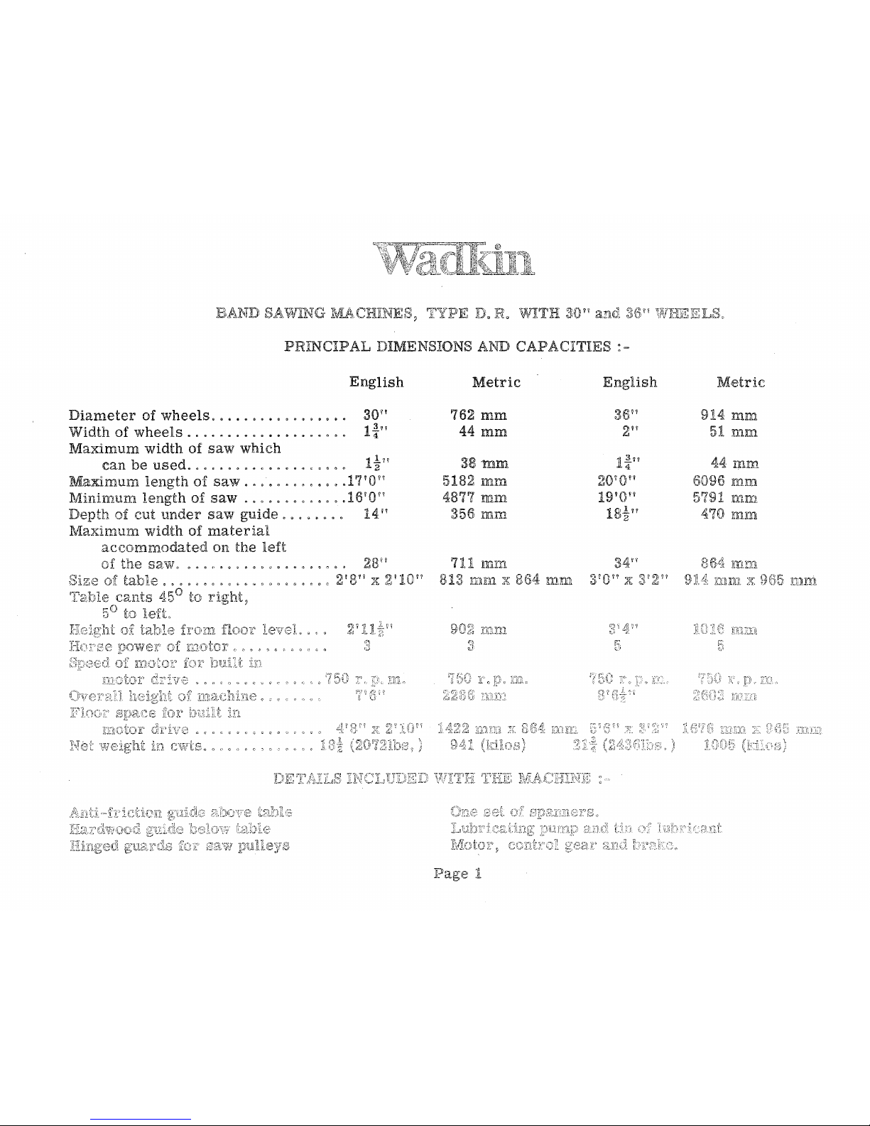
BAND
SAViJ1NG
Iv'lliCHINES~
PRINCIP
AL
DIMENSIONS AND
CAPACITIES
:
~
English
Diameter
of
wheels
.... , ...........
,
Width
of
wheels, , .............
0
••••
Maximum
width
of
saw
which
can
be
used
..............
0 • • • • • 1
~.f!
Ma.xirnum
length
of
saw
....
0
••••••••
1F{'0?7
Minimum
length
of
saw
.............
1610"
Depth
of
cut
under
saw
guide
..
, . . . . .
II
Max:lr.llum
width
of
material
accommodated
on
the
left
right,
'!'
Metric
762
mm
44
mm
38mm
5182 ml11.
4877
mm
356
mm
711
m!11
81:i
111Krl
z;:
8
English
mm
EL~L
Metric
914
ml1l
51
fin'].
'14
mm
6096
J(n:m
57~n
mm
470
mm
5
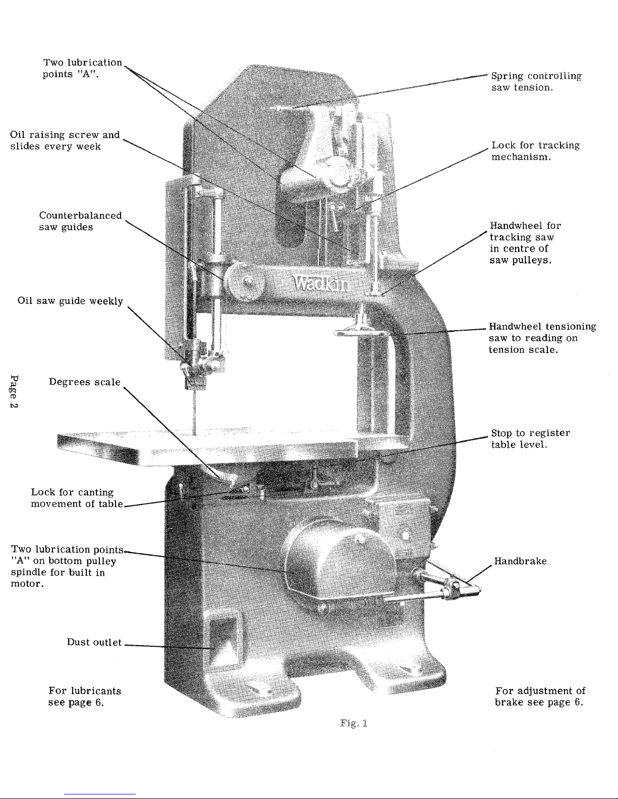
Two
lubrication
points
"A".
Oil
raising
screw
and
slides
every
week
Counterbalanced
saw
guides
Oil
saw
guide weekly
'"d
Degrees
scale
~
CD
t-:I
Lock
for
canting
movement
of
table
Two
lubrication
l'vuu
.... -__
_
"A" on
bottom
pulley
spindle
for
built
in
motor.
Dustoutlet
__
_
For
lubricants
see
page
6.
Fig.
1
Spring
controlling
saw
tension.
Lock
for
tracking
mechanism.
Handwheel
for
tracking
saw
in
centre
of
saw
pulleys.
___
Handwheel
tensioning
saw
to
reading
on
tension
scale.
Stop to
register
table
level.
Handbrake
For
adjustment
of
brake
see
page
6.
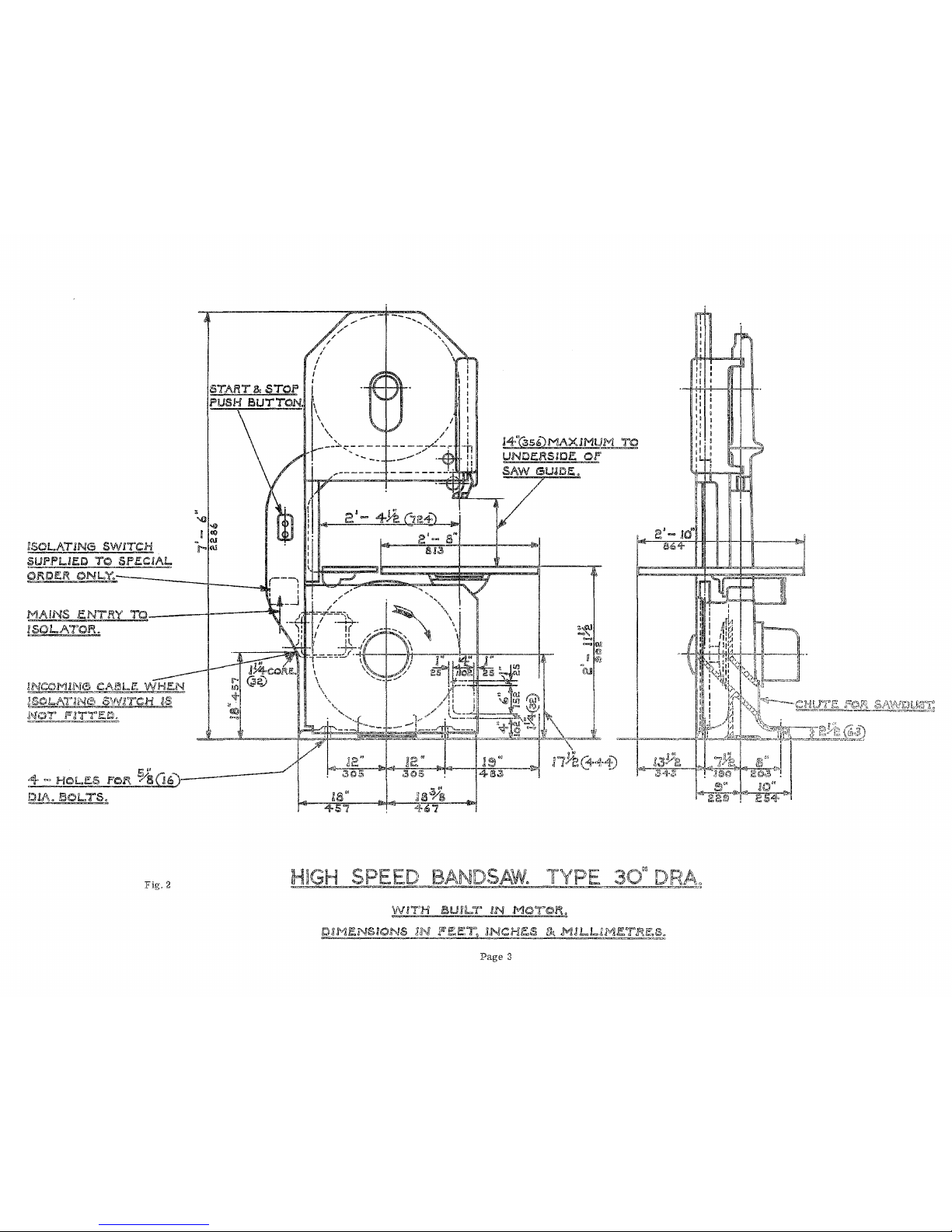
!SOL.A.'TKNG
SW!TCH
~PUE.O
TO
Sf'.ECJAL
QROER
PNL~
____ , ________ ~ ____
~
~AINS
ENTR~'rO----~4-----~~
!SO!...ATOR.
lNCOMING
Cd,\!'!lL~e:
WHEN
!§_SH
••
,A:-r3~TCH
IS
NO'!'
,",fTr.J:~
4-
~-
HOLf.S
rOl't.
o/sOt;"}--
CJI\.. fJOL..TS.
Fig.
2
I
/
'"
---;,,-/--t-
--
14"(§56)MAXIMUM
yo
UNDERSJO.E
OF
SAW
GUJDE,.
-
7-
:,,~
~~
~'I\I
C>
!
@}
~ru
iilGH
SPEE,Q
BANDSAW.
TYJ?E
3Q'I,ORl:\',
Wf1Ji
lSWL.T
AN
I1.~R.
D2l"-j~NSmNS
IN
F~J::'L
U',!CIi~&
,Ml~L..tM,I!,T.f:Ic;,§!~
Page
3
1
I
J>OCA
,INO
=CH
.•
J
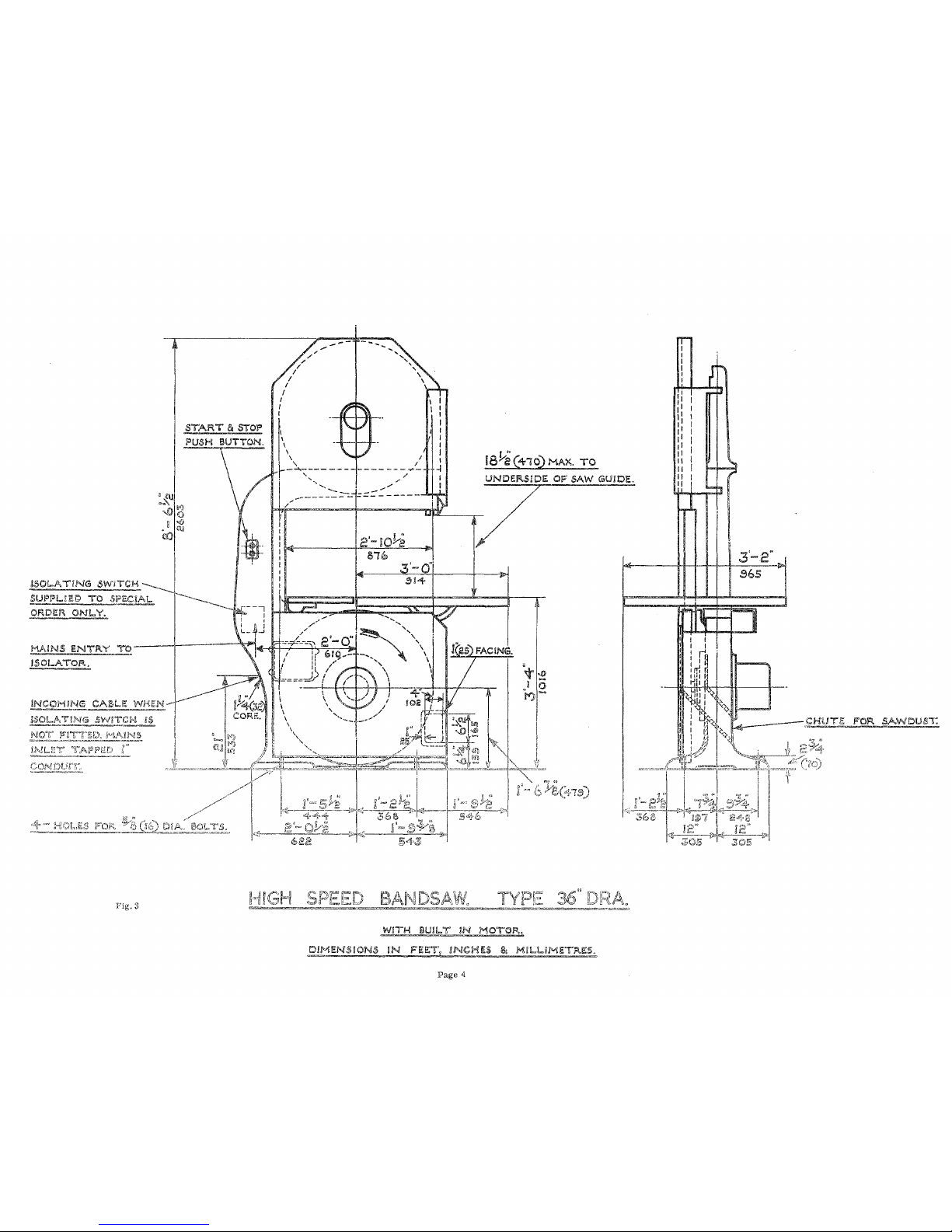
START
III
STO!"
PUSH
BUTTON.
SUI"l"!..nH~
TO
5l"EC!.A,!".
.----
___
-.....
ORDIZl'\
,ON
i_V.
"-
~c;,--:
-~---~---
I ,
MAINS
ENTFW
~ro'
lSOI_ATO!'!.,
Fig.
I A I
t
__
-r-.l
I"
IBYe
(410)
I''IAK
T.£
UNDEFl.SlDE
OF
SAW
GUIDE.
T/
7
i'11!..!..iMETi'i.E5.
~
-
,-
"""
Page
4
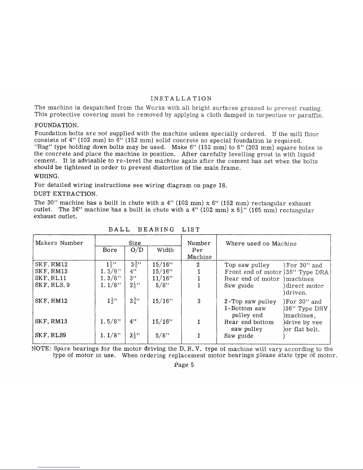
INST
LLATION
The
ma.chine
is
despatched
from
the
'Works
wi
all
bright
surfaces
greased
This
protective
covering
must
removed
applying
a
cloth
damped
in
FOUNDATION.
:Foundation
bolts
are
not
supplied
with
the
machine
unless
specially
ordered.
If
the
InHl
floor
consists
of
4"
(102
mm)
to
6"
(152
mm)
solid
concrete
no
special
foundation
is
requiredo
"Rag"
type
holding
down
bolts
may
be
used.
Make
6"
(152
mm)
to
8"
(203
mm)
square
holes
the
concrete
and
place
the
machine
in
position.
After
carefully
levelling
grout
with
liquid
cement.
It
is
advisable
to
re~level
the
machine
again
after
the
cement
has
set
when
the
bolts
should
be
tightened
in
order
to
prevent
distortion
of
the
main
frame.
WIRING.
For
detailed
wiring
instructions
see
wiring
diagram
on
page
18.
DUST
EXTRACTION.
The
30"
machine
has a built
in
chute
with
a
41V
(102
mm) x 6"
(152
mm)
rectangular
exhaust
outlet.
The
36"
machine
has a built
in
chute
with a 4"
(102
mm)
x 6il! (165
mm)
rectangular
exhaust
outlet.
BALL
BEARING
LIST
Makers
Number
Size
Number
Where
used
on
Machine
~-l
Bore
OlD
Width
Per
Machine
SKF.
RM12
1~"
3~n
15/16
11
2
Top
saw
pulley
)
For
30"
and
I
SKF.
RM13
1.
5/8"
4"
15/16" 1
Front
end
of
motor):3 I Type
DRA I
SKF
..
RL11
L
3/8
il
3"
It/16
H
I
1
Rear
end
of
motor
)machiues
I
SKF.
RLS. 9
lot/8Y!
2.!1!
5/8"
1 Saw
guide
)direct
motor
""2
)driven.
I
SKF.
RM12
1~V1
3t"
15/16"
3 2 ·-Top
saw
pulley ) For
30
IV
and
I-Bottom
saw
)36"
Type
DRV
SKF.
RM13
1.
5/8"
4"
15/16"
pulley
end
)machines,
1
Rear
end
bottom
)drive
by
vee
saw
pulley
)01'
flat
belL
SKF.
RLS9
1. 1/8!!
?,.!!1
5/8"
1 Saw
guide
)
""'2
NOTE~
Spare
bearings
for
the
motor
driving
the
D.
R.
V.
type
of
machine
will
vary
according
to
the
type
of
motor
in
use.
When
ordering
replacement
motor
bearings
please
state
type
of
motor,
Page
5

UBRICATION
"A n ~ 4:
POINTS (Shown
on
Fig,
,
Every:3
to 6
months
give
4 to 6
depressions
of
the
grease
gun
using
Wadkin
Ball
Bearing
Grease
Grade
L.
6,
For
lubrication
of
saw
guide
use
Wadkin
Machine
on
Grade
L.
4,
but
for
details
see
instruction
plate
on
inside
of
saw
guard,
The
raising
screw
and
slides
to top
saw
wheel
should
be
oiled
weekly
using
Wadkin
Machine
Oil
Grade
L.4,
The
machine
should
be
cleaned
down
weekly,
WADKIN RANGE
OF
OIL
AND GREASE WITH EQUIVALENTS.
Equivalent
Lubricants
Wad
kin
Grade
..
Shell
Mex
and
B.
P.
Ltd.
Vacuum
Oil
Co.
Ltd.
CaUex
Lubricants
_",,=~_.
~_
..
~·_c
Oil G rade
L.
4
Shell
Vitrea
Oil
33
"Vactra
II
on
Caltex
Aleph
Oil
(Heavy
Medium)
BaH
Grea
Bearing
Shell
Nerita
Grease
3
Gargoyle
Grease
BRB3
Regal
Starfak
se
Grade
L.
6.
.
...
.
~'-".
Fig
0
4:
BRAKE
AD
..
TUSTMENT
The
brake
is
carefully
adjusted
leaving
our \Vorkso
If
wear
takes
place
brake
linings
after a period
of
running,
the
nuts'
must
be
screwed
sufficient:
only
make
brake
effective
when
controlled
Fig" 5
PLAIN
FENCE
type
fence
will
quite
efficiently
on
either
side
of
savSj
0
No.2
Grease
Fig> 6 CANTING
FENCE
The
canting
fence
is
supplied
to
on
either
the
left
or
side
of
the
saw.
Please
specify
which
hand
of
fence
is
desiredo

FITTING
BANDSAW
BLADES
SAW
GUIDES -
Fig.
7.
When
placing a saw
on
the
machine
the
top
and
bottom
guides
must
be
moved
well
back
and
the
saw
tracked
or
adjusted
to
run
in
the
centre
of
the
saw
wheels.
Afterwards
bring
both
guides
forward
until
the
discs
barely
touch
the
saw
when
not
working
..
The'side
blocks
on
the
guides
should
support
the
saw
on
the
sides,
but
not
allowed
to nip
the
blade.
Keep the
side
blocks
up' to the
gullets
(if
the
teeth
only
leaving
the
teeth
clear.
When
using
saws
of
the
same
width
they
will
usually
run
successfully
without
altering
the
adjustment,
but
when
wider
ones
are
used
the
guides
must
be
moved
back
and
the
saw
re-tracked.
To
obtain
first
class
sawing,
the
guides
must
be
dead
in
line
and
fixed
immediately
above
the
work.
TENSIONING -
Fig.
8.
Incorrect
tension
or
tightness
of
the
blade
over
the
saw
will
end
in
saw
breakage.
The
scale
and
pointer
are
set
before
despatch,
but
should
they
be
displaced
in
transit
it
is
necessary
to
re-set
them
before
use.
In
placing a saw
on
the
pulleys
it
should
be
sufficiently
tight
until
it
can
be
pulled
out
ttl
from
its
true
line
at a central
point,
between
the two
pulleys.
When
this
is
done,
move
the
pointer
until
the
scale
coincides
with
the
width
of
the
saw.
For
a
~"
blade. the
pointer
should
read
~".
If
the
machine
is
left
standing
for a period,
e.
g.
overnight,
the
tension
should
be
reduced,
and
the
blade
re-
tensioned
before
putting
the
machine
into
operation
again.
IMPORTANT.
After
the
pointer
is
fixed
in
this
manner
it
will
read
correctly
for
any
width of
blade
without
further
alteration,
even
if
the
length
of
saw
varies
for
any
given
width.
For a i"blade
the
pOinter
should
read
i",
etc.
Page
7
and
Pointer
Fig.
7

FITTING
BANDSA
W
BLADE
S (Continued)
TRACKING - Fig. 9.
Every
saw
has
slightly
different
running
characteristics
on a
band
saw
machine
due to the condition of the
steel
ribbon
it
is
made
from,
the
brazed
joint
and
the
tension
in the
blade
ribbon.
This
is
compensated
by
using a crowned
(O,r
slightly
curved)
rubber
on the
wheels
and
prov-
•
iding the top wheel with a
slight
tilting movement.
We
call
this
track-
\
ing
and
by
slackening
the
lock
handle
and
adjusting
the
tracking
hand-
wheel,
it
is
possible
to
adjust
the
tilt
of the top wheel,
so
that the
saw
runs
steadily
in the
centre
of the wheel.
This
is
important
because
the
blade
then
passes
in a
straight
line
between the top and bottom
wheel, and does not snake. When the
latter
occurs
the
back
of the
saw,
keeps
hitting the guide
plate
and
woodwork and damaged guides
result.
Do
not
forget
to
re-tighten
the
tracking
lock
bolt
after
adjusting.
SAW
PULLEYS
A
brush
as
shown
in
Fig. 10
is
provided
on the
bottom
pulley to
remove
sawdust,
whilst
the
rubber
on the top
pulley
should be cleaneq daily to
prevent
accumulation
of
sawdust
which would
cause
the
blades
to
run
out
of
true
line.
.
The
saw
pulleys
must
be
kept
in
accurate
balance
to avoid
vibration.
It
is
essential
that
the
rubbers
on the
faces
of the
pulleys
are
kept
at
an
even
thickness
by
truing
up
occasionally
or
if
they
are
badly
worn
should
be
replaced
by new
ones.
If
the
machine
is
used
with badly
worn
pulleys
the
saw
will
vibrate,
resulting
in
bad
sawing and
broken
saws.
We
have a
service
arrangement
which we
recommend
whereby newly
rubbered
pulleys
can
be
supplied
against
the
return
of the
existing
pulleys,
an
appropriate
charge
being
made
to
cover
re-rubbering
only.
Where
it
is
not pra.ctical
for
the
customer
to
use
our
exchange
service
of
vulcanised
wheels
it
is
possible
for
the
customer
to
carry
out
his
ownre-rubbering,
which,
whilst
not
so
good
as
the
vulcanised
process,
is
satisfactory
if
the
instructions
below
are
carefully
followed. Rubber
bands
and
fixing
solution
can
be
supplied to
order.
Page
8
fC!r
tr::acking saw
Brush
Fig.~
Fig. 10

REMOVAL
OF
SAW
PULLEYS.
The top
and
bottom
pulleys
are
idelltical,
and
when taking
them
from
the
machine
for
re-rubber-
ing the
entire
wheel
comprising
plate
and
hub
should
be
removed.
To do
this
remove
the
spindle
nut
and
withdraw the
wheel
complete.
It
should
be
noted
that
for
both
pulleys
this
locknut
has
a
left
hand
thread.
FIXING INSTRUCTIONS FOR THE APPLICATION OF RUBBER
BANDS
TO
BAND
SAW
PULLEYS.
The
Croid
Glue
No.9
supplied
is
ready
for
use
and
should
be
applied
cold.
In cold
weather
and
if
the glue
is
solidified
warm
up to 800 Fahrenheit
to give fluidity
and
to
assist
spreading.
Thoroughly
scrape
and
clean
the
face
of the wheel
free
from
old
abrasive.
This
is
very
import-
ant.
Stretch
the
rubber
band
over
the wheel.
To
assist
with the
application
of the glue
it
will
be
found
more
convenient to
place
between
the
wheel
rim
and
the
rubber a piece
of wood
approximately
lin
diameter.
Apply the glue
across
the
face
of the
wheel
and
turn
the wood
round
the
rim
thereby
exposing a
section
of the
rim
to
be
glued.
Proceed
until
the whole of the wheel
has
been
covered
taking
care
to
glu"e
the whole
face
in
order
to
obtain
adhesion
over
the whole width to
prevent
the
edges
of
the
band
lifting.
Tightly
apply a
piece
of
tape
of the
same
width
as
the
wheel
around
the
circumference,
thereby
giving
as
much
pressure
as
possible
to the
rubber
band.
Leave
at
least
24
hours
before
use.
Finally
true
up the
rubber
and
put a slight
crown
on the
face.
This
is
done
by
revolving
the
wheel
and
holding
against
it
a wood
block
covered
with
emery
cloth,
preferably
when mounted
on the
machine.
Check wheel
for
balance
before
use.
FOR TROPICAL COUNTRIES a
Croid
Glue No. 10
is
supplied
with a
hardening
powder
which
must
be
added
in
the
proportion
of one
part
of
hardener
to
56
parts
by
weight
of
glue
and
thoroughly mixed. The
remainder
of
the
procedure
for
cleaning
and
fixing
is
the
same
as
in
the
instructions
above.
Page
9

MAINTENANCE
OF
BAND
SAW
BLADES
A
properly
sharpened
band
saw
win
give
clean,
accurate
cutting
and
this
is
achieved
by
proper
setting
and
sharpening
of
the
teetho
Always
set
before
sharpening.
SETTING.
In
order
to
cut
satisfactorily
band
saw
teeth
must
be
seL
This
consists
in
bending
the
teeth
alternately
out
of
the
Hne of
the
blade.
This
presents
alter·
nate
pairs
of
teeth,
wider
than
the
thickness
of
the
ribbon
and
prevents
the
ribbon
rubbing
in
the
wood
being
cut
and
getting
hot
usual
1J'Jays
of
setting
depending
generally
to
be
done.
Saw cut
a
hand
setting
tool
of
the
pUeI'
Amount
of tooth
set
over
shown
shaded
Set
Set
Body of
saw
settingo
Th!~
standard
filing
machine
described
on
page
15
can
be
changed
to
action~
but
many
firms
prefer
to
install a separate
inexpensive
Inachine
2~S
described
on
page
HL
The
difference
between
the
machines
(Figures
15
eapacity
of
saw
width
and
pitch~
and
the
advantage
of
these
machines
is
that
push
the
teeth
over ~ are
arranged
on
opposite
of
the
blade ~ and
sirnultaneously,
In
this
WO'ilY
shock
two
strikers
cancel
each
not
damag€~
the
band
ribbon,
cannot
be
~~nsur!2:d
are
cutting
O'f:lerCOlJl."JJ8
U:l.is
the
shmJ1ld
be
stoned
occaSJlonaUy. An
ordinary
grit
ston~::
is
used
ball
bearing
gujde
should
temporarily
be
brought
forwarduntn
the
thrust.
disc
is
Jin
contact
the
back
of
the
blade.
The
blade
should
then
be
run
and
the
stone
carefully
applied
to
the
teeth
each
side
of the
blade.
Vlhen the
saw
is
subsequently
sharpened
it
will
be
noted
that
each
tooth
has
not
been
marked
with
the
stone,
and
such
teeth
should
only
Page
10

SETTING
(Continued)
be
filed
very
slightly.
The
remainder
of
the
teeth
which
have
actually
been
stoned
should
be
filed
111
the
used
manner
until
the
flat
caused
by
the
stone
disappears.
Bands::tws
may
be
stoned
approximately
once
to
every
six
sharpenings.
The
points
of
the
teeth
are
set
by.
using a handsetting
tool
of
the
plier
type.
The
points
only
of
th.e
teeth
m.ust
be
set
and
as a general
guide the
set
on
each
side'is
.010".
Set
is
applied
in
opposite
d:i.:rections
for
each
alternate
tooth.
SHARPENING.
This
is
normally
done
by
using a triangular
section
file.
Again
the
operation
can
be
done
by
hand.
or
machine.
HAND FILING.
It
is
essential
to
employ
an
efficient
and
quick
acting
vice
and
round
cornered
triangular
fHes,
both
as
illustrated
on
page
14.
The
face
of
each
tooth
should
be
filed
across
and
with
the
same
stroke
the
back
of
the
following
tooth
should
be
filed
at
the
same
time.
One
stroke
of
50
positive
hook
the
file
should
be
sufficient
to
sharpen
each
tooth,
and
this
stroke
should
be
as
light
as
possible
in
order
to
avoid
prod=
ucing a burr.
The
shape
of
the
gullet
is
automatically
maintained
at
60°
by
the
50 negative
hook
file,
while
the
angle
of
the
hook
on
the
File
Rounded
Gullet
;'1~
Positioning
of
file
Page
11
tooth
is
dependable
on
the
positioning
of
the
file.
For
general
"work
approximately
5°
of
positive
hook
should
be
given, A
greater
or
smaller
hook
should
be
applied
for
softer
or
harder
woods
respectively.
In
the
case
of
particularly
hard
woods
a
negative
rake
may
be
necessary
~
'whilt::
a,
wider
LOOUl
pitch
than
standard
may
be
required
for
sawing
Um.ber"s
an
abrasive
nature ~ and
those
containing
gum,

SHAHPENING (Continued)
Ahr.rays
sharpen
square
across
the
face. of
each
tooth
and
NOT
on
the
bevel,
otherwise
the
saw
will
vibrate
violently,
which
shatters
the
steel
and
cracks
appear
causing
saw
breakage.
Use a file
with
rounded
corners
and
of
triangular
section.
It
is
important
to
keep
the
gullet
of
each
tooth
rounded
otherwise
cracks
will
soon
appear,
Saws
111USt
he
sharpened
at
regular
intervals
and
should
never
be
forced
to
cut
with
teeth
which
have
become
blunL
V/hen
reconditioning
handsaw
blades
is
necessary
to
set
the
teeth
first
before
sharpening.
This
ensures
that
the
face
of the
File
position
/
Face
of
each
tooth
to
be
sharpened
square
across.
Note:-
Rounded
gullet
tooth
is
squar(~,
If
the
sharpening
were
carried
out
first,
the
subsequent
setting
would
result
an
angular
tooth
shape
being
obtainedo
A
picture
the
automatic
machine
for
filing
blades
is
given
on
page
15.
}<"'urther
detaHs
of
this
machine
will
be
forwarded
on
request.
Page
12

GENERAL
CAUSES
OF
SAW
TROUBLE,
CRACKING AND
BREAKAGE
L
Crystallisation
of
the
ribbon,
produced
by
the
back
of
the
saw
rubbing
against
the
metal
disc
of
the
saw
guide,
The
disc
should
revolve
only
by
contact
with
the ba.ck
edge
of
the
saw
when
actually
cutting.
2.
Using a blade
that
is
too
wide
for
the
radii
being
cuL In
attempting
to
curves
with a saw
too
wide
the
blade
tends
to
twist
against
the
guides
causing
friction
and
over-
heating
which
destroys
the
temper
in
the
steel.
SMALLEST
RADII VI/HICH
)VLA Y BE
SAWN WITH GIVEN WIDTH OF'
BLADE
r~idth
of
Blade
~in:i.m\'i.m
Radius
I
I
L
1/8
t
! 3/16!!
1/Bj17
5/1~':
---------~'--.--
---
NOTE:
ALWAYS USE \!'iIIDEST
BLADE
COMPATIBLE
"WITH
THIS
CHART.
Not
enough
set.
with
a
details
brazing
Page
13
File

TAPER
TRIANGULAR
FILES
FOR
HAND USE
Fig.!I
Length
..
6"
8"
10"
The
edges
of
both
machine
and
hand
files
have
rounded
corners
to
produce
the
round
gullet
which
prevents
saw
cracks.
Fig.
12
BAND
SAW
FILING
VICE
A
specially
designed
vice
for
holding
band
or
fret
saws
also
handsaws.
Jaws
are
17"
long
and
will
take
saws
up
to
2~"
wide.
Jaws
open
instantaneously
by
lever
handle.
Spare
handsaw
blades
for
wood
cutting
on
the
30"
and
36"
D. R.
Bandsaws
are
available
from
stock.
(Maximum
and
minimum
lengths
given
on
page
1).
Where
it
is
preferred
bandsaw
blading
in
strip
form
can
be
supplied
for
customers
to
make
up
their
own
blades.
This
bandsaw
strip
is
offered
either
toothed
only"
or
toothed,
sharpened
and
set.
SPECIAL
MATERIALS.
In
addition
to
woodcutting
we
can
supply
bandsaw
blades
suitable
for
plastics,
bonded
wood,
non~
ferrous
metals ~ meats
etc.,
providing
that
the
correct
machine
speeds
are
available.
If
any
special
material
is
to
be
cut, a sample
should
be
sent
to Wad1dn
Ltd.
for
test
purposes
so
that
the
correct
type
of
blade
may
be
recommended.
We
are
able
to
offer
special
speed
bandsaws
for
specific
purposes
and
full
details
will
be
sent
on
request.
Page
14

WADKIN
BAND
SAW
FILER
AND
SETTER,
TYPE
H.
D.
This
machine
is
fully
automatic
and
ensures
that
each
tooth
is
sharpened
and
set
to tbe
correct
shape
and
depth.
Any length of
saw
can
be
dealt
with,
and
the
maximum
width
is
2i"
with
teeth
up to
5/8"
pitch
for
filing
and
1~"
wide
for
setting.
Fig.
13
Fie:. 14
WADKIN ELECTRIC BAND
SAW
BRAZER.
TYPE
H.E.
This
machine
is
suitable
for
brazing
band-
saws
from
i"
to
1"
wide,
and
is
very
useful
for
the
efficient
brazing
of
blades
which have
become
broken.
The two
ends
of the
saw
are
firmly
held
by
the
clamps,
and
controlled
heat
applied
electrically.
A
small
quantity
of
solder
and
brazing
compound
are
supplied
with
the
machine.
The
actual
brazing
takes
from
25
to 45
seconds
according
to
width
of
blade.
Before
brazing
the ends of
the
saw
blade
must
be
carefully
bevelled. A separ-
ate
instruction
chart
is
issued
with
the
brazer.
Page
15

When
the
amount
of
work
does
not
justify
the
installation
of
the
equipment
shown on
page
15 we
can
offer
a
prompt
and
efficient
repair
and
reconditioning
service.
Any
blades
sent
to
us
for
reconditioning should
be
covered
by
an
official
order.
WADKlN
,BAND
SAW
SETTING MACIDNES
For
manual
setting
the following equipment
is
recommended.
Fig. 15
FOR BAND
SAW
BLADES UP TO
3"
WIDE
7/8"
PITCH
TYPE
B/LS
This
is
a heavy duty
machine
which
sets
two
teeth
at
each
revolution,
giving a
rate
of
approx-
imatel
y 200
teeth a minute
on the
general
run
of work. .
The
machine
may
be
used
either
by
hand
or
power,
the
handwheelbeing
in
the
form
of a
pulley
to
take a belt
from
motor
or
lineshaft.
Fig. 16
FOR NARROW
BAND
SAWS
UP TO 1 i"
WIDE
t"
PITCH
TYPE
Blss
All
adjustments
are
quickly
and
easily
made
to
this
robust
and
thoroughly
practical
tool.
It
is
usually
operated
by
hand
and
setting
is
at
the
rate
of two
teeth
per
revolution
of wheel. When
preferred
the
machine
may
be
power
driven
by
flat
belt
on
the
pulley
face
of the handwheel.
Page
16
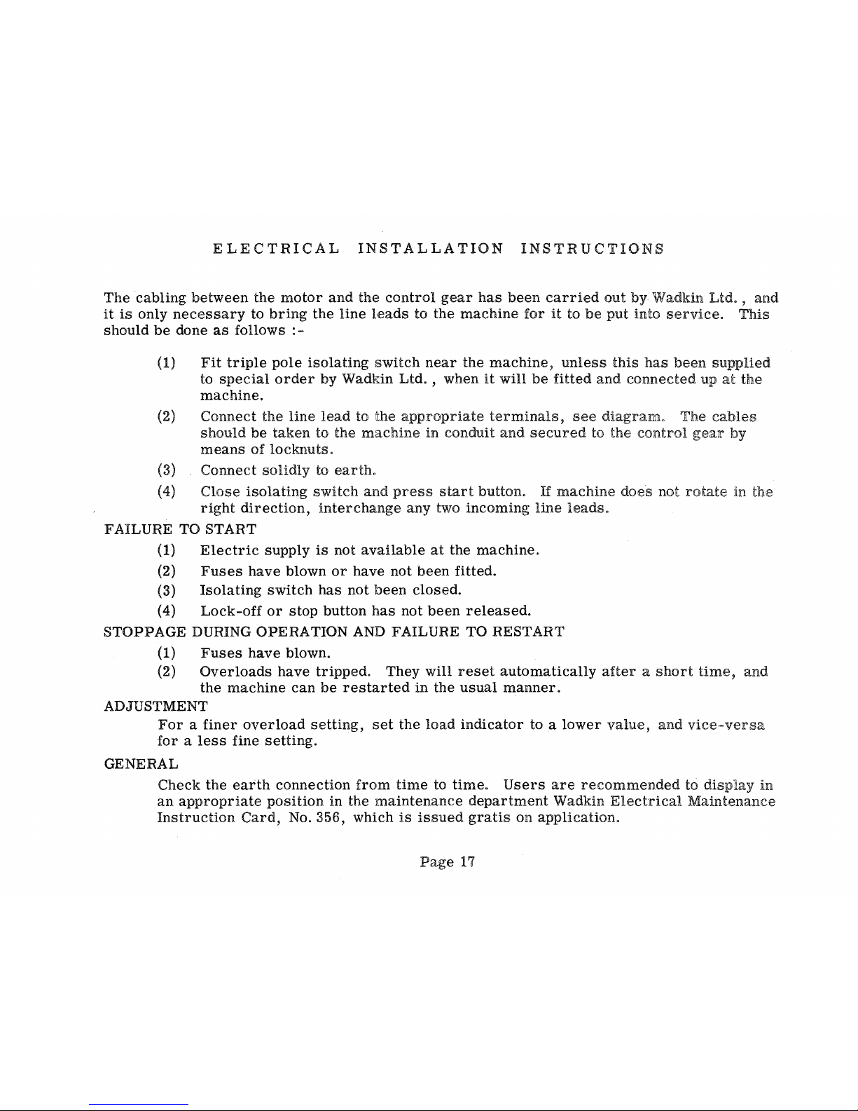
ELECTRICAL
INSTALLATION
INSTRUCTIONS
The
cabling
between
the
motor
and
the
control
gear
has
been
carried
out
by
Wadkin
Ltd.,
and
it
is
only
necessary
to
bring
the
line
leads
to the
machine
for
it
to
be
put
into
service.
This
should
be
done
as
follows
:-
(1)
Fit
triple
pole
isolating
switch
near
the
machine,
unless
this
has
been
supplied
to
special
order
by Wadkin Ltd. , when
it
will
be
fitted
and
connected
up
at
the
machine.
(2) Connect the
line
lead
to the
appropriate
terminals,
see
diagram.
The
cables
should
be
taken
to the
machine
in
conduit
and
secured
to the
control
gear
by
means
of
locknuts.
(3) Connect
solidly
to
earth.
(4)
Close
isolating
switch
and
press
start
button.
If
machine
does
not
rotate
in the
right
direction,
interchange
any two incoming
line
leads.
FAILURE TO START
(1)
Electric
supply
is
not
available
at
the
machine.
(2)
Fuses
have
blown
or
have not
been
fitted.
(3)
Isolating
switch
has
not
been
closed.
(4)
Lock-off
or
stop
button
has
not
been
released.
STOPPAGE DURING OPERATION
AND
FAILURE TO RESTART
(1)
Fuses
have
blown.
(2)
Overloads
have
tripped.
They will
reset
automatically
after a short
time,
and
the
machine
can
be
restarted
in
the
usual
manner.
ADJUSTMENT
For a finer
overload
setting,
set
the
load
indicator
to a
lower
value,
and
vice-versa
for a less
fine
setting.
GENERAL
Check the
earth
connection
from
time
to
time.
Users
are
recommended
to
display
in
an
appropriate
position
in
the
maintenance
department
Wadkin
Electrical
Maintenance
Instruction
Card,
No. 356, which
is
issued
gratis
on application.
Page
17

.
r-
oo
-..0
.;
z
t-
ILl
..J
...
4:;
IaJ
..J
ILl
ILl
",
"
<
ILl
~.
..J
4:;
u
it
t
ILl
.
..J
ILl
ILl
~
~
IaI
0
a:
IaI
L
fa.
ILl
t!)
0:
Z
ILl
Z
0::
';5
::J
...
..J
~
U
0:
a:
0
11.
fa.
0:
I
IIJ
<
~
0::
J
19
10
<
U
a
~
U)
x
0
r
~
z
ILl
~
bJ
J
III
10
0::
~
iI:
0
Il.
Z
~
0
~
II.
0
~
<
.J
:>
u
~
0.
"
f
MAINS
:SUPPLY
PARTICULARS
VOLTACSE
TRIPLE POLE ISOLATING
SWITCH.
To
SPECIAL.
ORDER
ONL.~---------
FUSES.
L.OCKNUTS.
PHASE
FREQ.UENCY
OUTPUT
PUSH ISUTTON
CONDUIT
HOLE
'z~"
STATION.
,,-------------------------------
-~---
....
\ I
rSTQP--START; I
r----------------------------
I I
I I :
~
I
In:
I I
I c.=:::I I I I
I
o-+'~'r_,'
----~
I
.1
L
___________
...J
TRIP
~
~;-'IJ'Y'
I
II
" I
I " I L
-1
I
:1
I.
,
I:
I
,
I
I
I
I
I
TO
A2. -
62
-
C2.
AT
CONTACTOR.
A!lRlczl
A2W
AIW
AIW
STAR
O~L.IA
I'
~"
I
C2
':
ji
l
r,----------f'\
: OVERLOAD .
FOR
MOTO",
:
:
HEATER
:1
II
rI I I h
-----..;;..I~i-1--+-_!-""+_
..
,CONNECT~S
r--l
:
COIl:06.
",I
I
LJ
I I
lr--'
L______________________________
SEe:
ABOVE
I I
\.
):
~-,----,--~
-----------------------:---------",
L...
L..
___
.J
L..
__
..J
CONIACTOR
MOUNTED
ON
DOOR.
INSTALLATION
INSTRUCTIONS.
FITTRIPL.E
POL.E
ISOL.AIINe
SWITCH
NEAR
MACHINE UNL.ESS SUPPL.IED
BY
WADKIN
L.
TO.
TO
SPECIAL.
ORDER,
so
THAT
THE
EL.ECTRICAL.
GEAR
MAY READIL.Y
BE
ISOL.ATED FOR
INSPECTION
PURPOSES.
BRINe
L.INE CABL.E.S
TO
ISOL.AIING
SWITCH
AND
TO
L.I
- L.2 -
L.3
AT
CONIACTOR
THROUISH
CONDUIT
WHICH
SHOUL.D
BE
SCREWE.D
INTO
THE
MACHINE
AND
SECURED
BY
MEANS
OF
LOCKNUTS. A HOL.E
15
PROVIDED
IN
THE
MACHINE
FRAME
AT
'Z·
FOR
THE
CONDUIT
CARRYINIS
IHE
L.INES
10
IHE
CONTACTOR.
OPERATING
INSTRUCTIONS.
TO
START
MOTOR,CL.OSE
ISOL.ATINIS
SWITCH
AND
PRESS
START
BUITON.
TO
SlOP
MO-rOR
PRE.SS
S,.OP6UliON
•• 0 L.OCK
OFF
MACHINE
PRESS
AND
TURN
SlOP
BUTTON.IHIS
MUSI
BE.
REL.EASED
BEFORE A START
CAN
BE
MADE..
NOTE:-
CABL.INCS
SHOWN
THUS
~
TO
BE
CARRIEO
OUI
BY
CUSTOMER
tJNLESS
150LA,.INIS
SWIICH
HAS
BEEN
FII,.EO
BY
WAQKIN
L.TD.
\
,
i
I
I
l I
........
IMPORTANT.
MOTOR
SECURE
L.INE CABL.ES
AI
'X'
BY
MEANS
OF
THE
CL.EAT
PROVIOED.
LEAVE
SUFFICIE.NT SL.ACK IN
LINES
AT'Y'
TO
AL.L.OW
THE
OOOR
TO
OPEN
FREEL.Y.
WHEN
DUAL
VOL.
TAISE
MO"ORS
ARE
EMPL.OYED
THE
FOL.L.OWINIS
CONNECI'ONS
SHOULO
BE
MADE
200
eso
VOL.,
CIRCUITS
CONNEC,.
MOTOR
IN
·OEL.
lA', 3 ....
0
440
VOL. T
CIRCUI'TS
CONNECI
MOIOR
IN
'STAR~
THE
CONNECTIONS
BEINIS
MADE
EITHER
WITHIN
THE
CONTROL
<SEAR.
CAVITY
OR
AT
IHE
MOTOR
TERMINAL.
BLOCK.
ENSURE
THAT
'THE
MACHINE
15
ADEQ,UATEl. Y 'EARIHEO'
AND
THAT
THE.
DIREC-rION
OF
RoTATION
IS
CORRECT
BEFORE
PU.-rINCS
INTO
SER.VICE.IO
REVERSE
ROTATION
INTERCHAN<SE
LI & La.
OVERLOAD.
SHOUL.D
IHE
MOIOR.
STOP
DUE
TO
OVERLOAD,
WAIT
FOR A SHORT
"TIME
TO
AL.L.OW
"THE
HEAlER
COIL.S
TO
COOL.
AND
THEN
START
IN
THE
USUAL
MANNER.
EARTH
MACHINE.
WAiKINL.
TO.
L.s.1CES,.ER.
DIAGRAM OF CONNECTIONS.
D.
191
3A.

T
lE
E ElE
RI
RS
l K F
Eft
T
E
SELVES
~
® ®
blow
away
harillful
(iust~
chips
and
dirt
with
a
Blo\ver
adkin
No
motor
can run at its maximum efficiency with its ventilating
duct
or
control covered with
dust
and
dirt.
Sooner
or
later
the
resultant overheating will cause serious
trou
Similarly, accumulations of
ips
and dust,
in
the
mechanical parts of
machine
can interfere with its efficiency. A few minutes a week
for blowing down
ali
Woodworking
Machinery will be amply repaid
in
better
and easier running,
in
increased life, and freedom from
breakdown.
Blowers
can
be supplied for single phase
A.c.
or
Direct
Current
for
any voltage
up
to
250.
Please state voltage when ordering.
SPECI
FICA
TION
Horse-power
of'motor
... :lnl
Net
weight...
7 Ibs.
Speed II
AGO
r.p.m.
Velocity
of
air
in
feet
per
minute
...
14,800
Fully
guarantesd
for
one
year

 Loading...