

Wadkin PP Series Instruction Book
"WADKIN"
www.DaltonsWadkin.com
www.DaltonsWadkin.com
www.DaltonsWadkin.com
DIMENSION
SAW
INSTRUCTION
TYPE
IIPP"
BOOK
NO:
987

Waakin
www.DaltonsWadkin.com
www.DaltonsWadkin.com
www.DaltonsWadkin.com
OPERATING
AND
MAINTENANCE
Wadkin
INSTRUCTIONS
Standard
Maximum
Depth
Throat
Saw
Maximum
Will
Length
Ripping
Horse
Speed
of
opening
cants
on
standard
crosscut
cut
power
of
fence
size
depth
cut
with
up to
distance
off
of
saw
spindle
of
saw
of
cut
saw
between
""
between
table
on
standard
using
cants
motor..
DIMENSION
PRINCIPAL
..
.
canted
fixed
..
"
""
saw
..
"
table
stop
on
up to
50
..
..
and
to
45°
and
..
"
and
..
with
mitre
60
cycles
SAW
DIMENSIONS AND CAPACITIES
sliding
".
"
fence
tables
....
...
ripping
.. ..
saw
at
..
.
.'
....
fence
..
90
0
..
.. ..
..
••
TYPE
P.
P.
:-
18"
5!"
3.
6"
45
30"
5!fi x
1
if X 36"
36"
45
5
2800
7/8"
0
29!"
0
r.p.m.
450
mm.
140
mm.
100
mm.
150
mm.
0
45
760
mm.
140 x 750
25 x 915
915
mm.
0
45
5
2800
r.p.m.
mm.
mm.
Details
One
pair
saw
collars
Motor
Saw
Single
and
guard
mitre
control
and
riving
fence
and
gear.
knife.
with
stop
nUt.
included
bar
and
with the
stop.
Page
1
machine.
Canting
Set
of
Tin
of
Ripping
spanners.
lubricant.
fence.
Wadkin
www.DaltonsWadkin.com
www.DaltonsWadkin.com
www.DaltonsWadkin.com
OPERATING
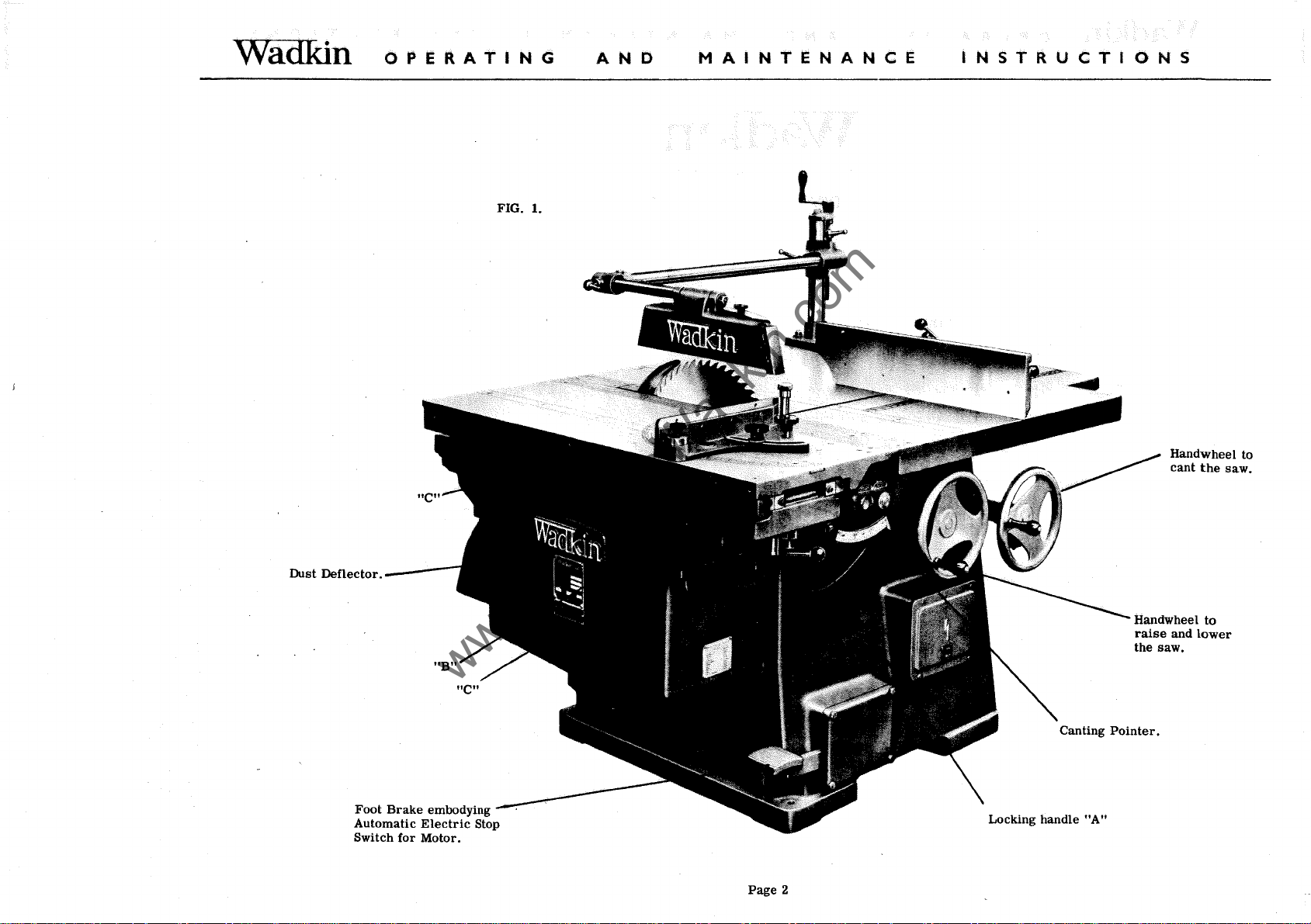
FIG.!.
AND
MAINTENANCE
INSTRUCTIONS
Handwheel to
cant
the
saw.
Dust
Deflector.
----
Foot
Brake
Automatic
Switch
for
embodying
Electric
Motor.
Stop
Page
Handwheel
raise
the
saw.
Locking handle
2
"A"
and
to
lower
Wadkin
www.DaltonsWadkin.com
www.DaltonsWadkin.com
www.DaltonsWadkin.com
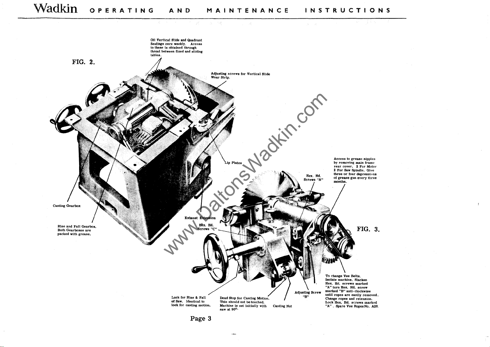
FIG. 2.
OPERATING
011
Vertical
Seatings
to these
throat
tables.
AND
Slide and Quadrant
once
weekly.
is
obtained through
between fixed
and
MAINiENANCE
Actess
sliding
INSTRUCTIONS
Access
to
by removing main
rear
cover. 2 For Motor
2
For
Saw Spindle. Give
three
or
Hex. Bd.
of
grease
months.
four
grease
depressions
gun
every
nipples
frame
three
Rise
and
Fall
Both Gearboxes
packed with
Gearbox.
are
grease.
Lock for
Rise " Fall
of
Saw. Identical to
lock
for canting motion.
Page
3
Dead Stop
This
should not
Machine
saw at
90
for
Canting Motion.
be
Is
set
initially
0
•
touched.
with Canting Nut
FIG. 3.
To change Vee Bella.
Isolate machine. Slacken
Hex.
Hd.
screws
"A"
turn Hex.
marked
ropes
until
Change ropes
Lock Hex.
"A"
. Spare Vee RopesNa. A28,
Hd.
"BH
anti-clockwise
are
easily
and
Hd.
screws
marked
screw
removed.
retension.
marked
Wadkin
www.DaltonsWadkin.com
www.DaltonsWadkin.com
www.DaltonsWadkin.com
OPERATING
AND
MAINTENANCE
INSTRUCTIONS
REMOVAL
Isolate
table
marked
main
from
cable
carrying
carriage
gearbox
dust
Fig.
machine
unit by
"B"
table
underside
from
handwheel
in 90
complete
deflector
2. Spindle
OF
SAW
SPINDLE CARRIAGE.
electrically.
removing
Fig. 1 and
and knock through two dowel
of body flange,
brake
degrees
and
carriage
locking
brackets
shoe.
these
position
with canting
exhaust
Remove
handles
lift
Remove
can now
using
screw
extension,
can now
marked
table
four
hexegon
be
withdrawn
wood
can
canting
be
removed
guard
marked
"C"
pins
from
clear.
blocks,
now
and
fence
"A"
Fig.
1. Remove
the top
Remove
head
from
be
withdrawn
pOinter
from
assemblies.
Fig. 1 and
and
electrical
screws
both
then
from
its
marked
gearboxes.
remove
from
lip
pOSition
Remove
lifting
tee
slot
remove
leads
"c"
canting
canting nut
plate
in
and
the
complete
table
clear
filling in
four hexegon
to
Fig. 3
Wedge
gearbox
remove
main
strips
motor
from
saw
see
Fig.
lip
frame.
sliding
of tenon
from
head
and
brake
each
spindle
pivot
pin,
3.
plates
Reassemble
screws
arm
Remove
see
in
the
reverse
Maintenance
Changing of
Changing of
Adjustment
order
that
motor.
spindle
to
wear
of
can
be
bearings,
strip
the above.
carried
of
out with
see
vertical
special
slide.
saw
spindle
instructions.
Page
4
carriage
Page
removed.
6.
WaOKin
www.DaltonsWadkin.com
www.DaltonsWadkin.com
www.DaltonsWadkin.com
J-~
1'01'.
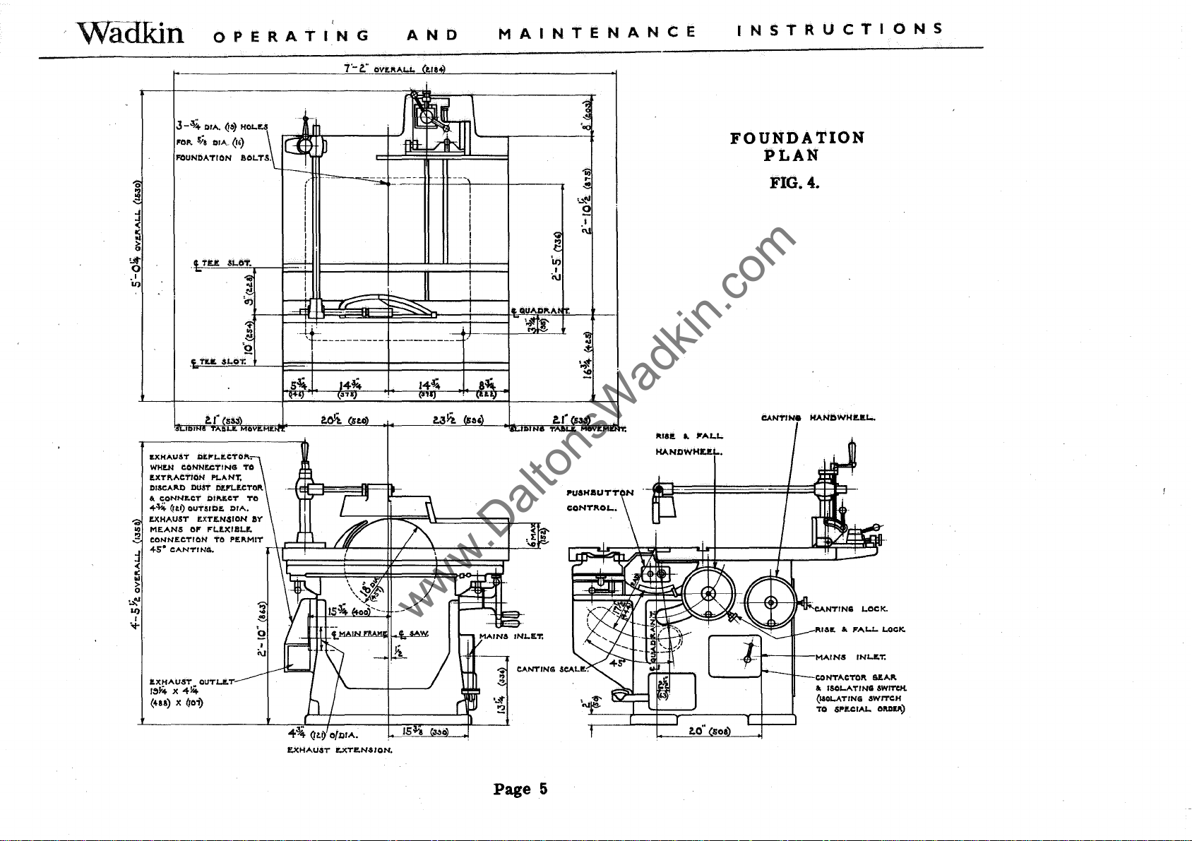
FOUNDATION
o
l§
~
~
~
o
.1
U)
OPERATING
OIA.
Q&)
H01.U
sia
01A..
(,,)
aOloTS.
AND
-1:----------
MAINTENANCE
..
r-
..
,~
o
INSTRUCTIONS
FOUNDATION
PLAN
FIG. 4.
IDJ
ItXHAUST
WHI!.N
r;XT!'.ACTION
DISCA!'.D DUST /If.l'lor;CTOR
&.
<!--¥.4.
..
I!.XHAUST
..
MEANS
!2
CONNECTION
j
<!-s'
-<
:i
>
o
'.:t;'
U)
I
.,..
~s~~A~~l&t.
(U8) le
DItP"1.ItCTO!'..
CDNNECTINEI TO
cONNItCT
<ltl) OUTSIDE.
ItXT£.N,sION
01'
CANTINEI.
QUT1.I!.T
(roi)
PLANT,
OII'.r;CT
P"1..!'l(llIlol!.
TO
14~
MOV'!'ME.
Ta
OIA.
ay
pr;
...
MIT
l-+F=l~:J...LfII-_--U-fL""':~
J
i\J
____
a
-..l-'~'~~::
-
Page
5
1\181t
..
Jl"AI..J..
HANDWHUJ...
loO"
soa
CANT/Ne
HANDWHUJ...
Rllllt
..
FALl..
LOCK.
CONTACTOR
&.
ISOJ..ATINEI SWITCH.
(UOloATING
TO 6Pl!.C IAI.. aMI!.!'.)
6ftA!'.
SWITCH
Wadkin
www.DaltonsWadkin.com
www.DaltonsWadkin.com
www.DaltonsWadkin.com
OPERATING
AND
MAINTENANCE
INSTRUCTIONS
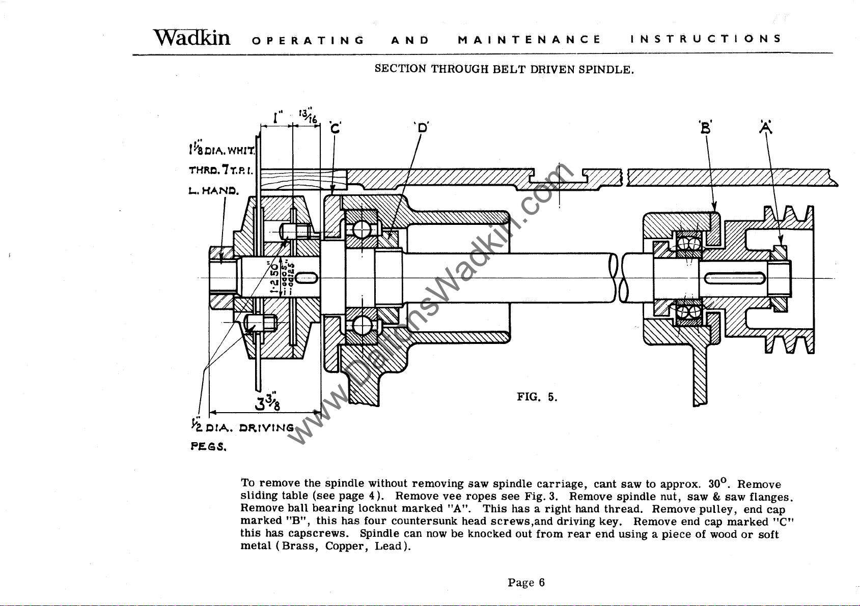
SECTION THROUGH
..
'c'
r~orA.
THRC.i~p.r.
L...
WHIT.
~~~~~~~~~~~~~~~~~~~
HAND.
BELT
DRIVEN
__
~https://manualmachine.com/
SPINDLE
.
~z.
CrA.
PESS.
CRfVrNG
To
remove
sliding
Remove
marked
this
has
metal
(Brass,
the
spindle
table
(see
ball
bearing
"B",
this
capscrews.
Copper,
page
locknut
has
Spindle
without
4).
Remove
four
countersunk
Lead).
removing
marked
can
now
saw
vee
ropes
"A".
head
be
knocked out
FIG.
spindle
see
Fig.
This
has a right
screws,and
Page
5.
carriage,
3. Remove
hand
driving
from
rear
6
cant
saw
spindle
thread.
key.
end
Remove
using a piece
to
approx.
nut,
Remove
0
30
.
saw & saw
pulley,
end
cap
marked
of wood
Remove
flanges.
end
cap
"C"
or
soft
Wadkin
www.DaltonsWadkin.com
www.DaltonsWadkin.com
www.DaltonsWadkin.com
OPERATING
AND
MAINTENANCE
INSTRUCTIONS
With the
bearing,
To
Reassemble.
Before
mentioned
the
hammer
The
The
spindle
assembly
bearings
the
inner
grease
removed
remove
clean
procedure,
with Wadkin
races
race
should
lubricant
rear
bearing
locknut
into
marked
out
all
ensuring
ball
position
be
a good
One SKF 6309 Saw
One SKF 1306 Saw
Four
SKF
recommended
"0"
old
lubricant,
that
bearing
but
push-fit
BALL
08 Two
Lubrication
this
no
grease,
give
is
Wadkin
can
dirt
be
lightly
has a right
assemble
or
grit
grade
gentle
on the
Shell-Mex
Mobil
Castrol
taps
spindle
BEARING
spindle
spindle
each
for
see
Figs. 2 and
Grade
Oil
tapped
hand
in
enters
L. 6. When
with a
front
rear
rise
out
thread,
the
reverse
the
bearings
soft
and
the
LIST
bearing.
bearing.
and
fall
of
its
fitting
rod
outer
and
housing. To
and
lightly
order
or
housings.
ball
all
round
race
a good
canting
tap off
of
the
previous
bearings
the
periphery.
sliding-fit.
motions.
change
bearing.
Smear
do
not
frent
3.
1....
6.
Alternative
& B.
P.
Ltd.
Co. MOBILUX GREASE No. 2
grease,
Shell
SPHEEROL
ALVANIA GREASE 3
S
For
oil
lubrication,
use
Wadkin
THOROUGHLY CLEAN DOWN MACHINE WEEKLY.
Grade
L.4.
Shell
Mobil
Castrol
Alternatively
Page
Mex &
Oil
Co.
7.
B.
P.
Ltd.
Shell
Mobil VACTRA
PERFECTO.
VITREA OIL 33
medium)
OIL
NN.
(heavy
Wadkin
www.DaltonsWadkin.com
www.DaltonsWadkin.com
www.DaltonsWadkin.com
OPERATING
AND
MAINTENANCE
INSTRUCTIONS
Grubscrew
depress
to
its
full extent.
will
prevent
for
fatigue and
To
replace
switch, disconnect
switch and
and
ensure
to
its
full extent the
the
grubscrew
To
set
first
lock by
secondary
in
anti-clockwise
marked
"A" Fig. 6
micro-switch
Failure
machine being
replace
micro-switch;
electrical
replace
switch on facing.
that when
marked
canting ripping fence
rotating
lock, this
direction
CANTING RIPPING
LOCKING ADJUSTMENT
FOOT
is
when foot pedal
of
brake
started,
if
necessary.
isolate
leads,
brake
pedal
micro-switch
"A".
for
clockwise, fine
also
squares
until dead stop
FENCE
OPERATED
initially
is
pedal to
check
machine,
set
operated
return
spring
remove
BRAKE ADJUSTMENT
to
connect new
Start
machine
arm
is
depressed
is
operated
by
"A"
FENCES, TABLE AND GUARDS.
cutting. Move fence to
adjust
to obtain
approximate
correct
dimension
position
fence to dovetail groove. To unlock fence
is
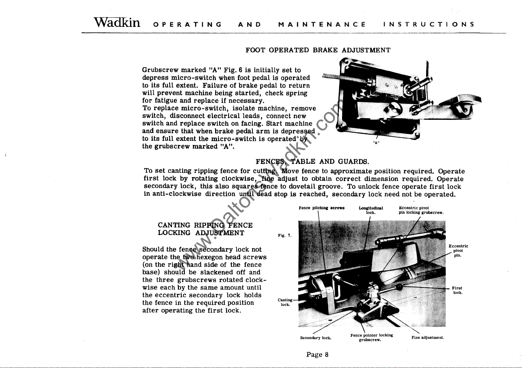
Fig.
reached,
Fence
7.
pitching
secondary lock need not be
screws
required.
required.
operate
operated.
Operate
Operate
first
lock
Should the fence
operate
(on the
base)
the
wise
the
the fence
after
the two hexegon head
right
should be
three
grubscrews
each
by the
eccentric
in
operating
secondary
hand
side
slackened
same
secondary
the
required
the
first
rotated
lock not
screws
of the fence
off and
clock-
amount until
lock holds
position
lock.
Canting
lock.
Secondary
Page
lock.
8
Fence
pOinter locking
grubscrew.
Fine
adjustment.
Eccentric
pivot
pin.
First
lock.
WadKin
www.DaltonsWadkin.com
www.DaltonsWadkin.com
www.DaltonsWadkin.com
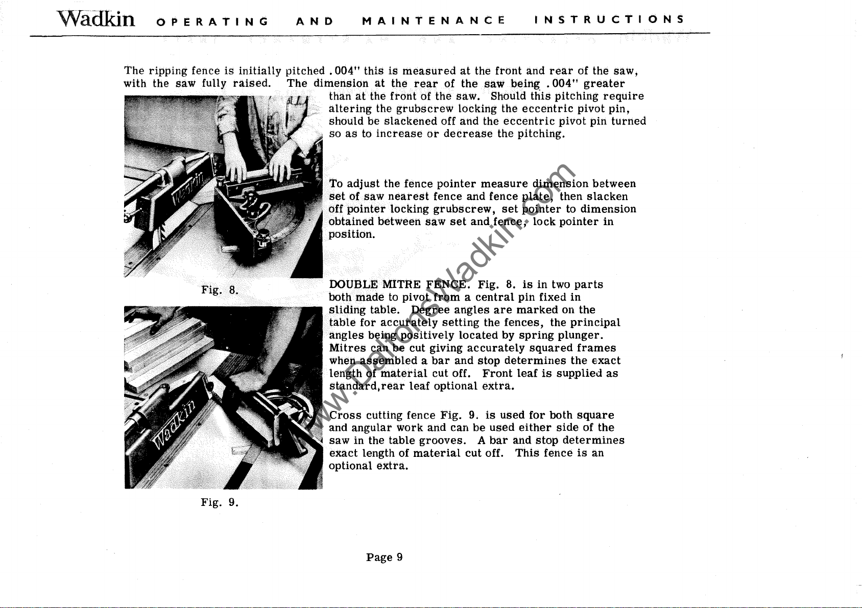
The
with
OPERATING
ripping fence
the
saw
fully
is
initially
raised.
AND
pitched
The
dimension
MAINTENANCE
.004"
than
altering
should be
so
as
at
this
at
the
to
is
measured
the
rear
front
the
grubscrew
slackened
increase
of
of the
off
or
decrease
at
the
front
the
saw
saw.
locking the
and
Should
the
eccentric
the pitching.
INSTRUCTIONS
and
rear
being . 004"
this
pitching
eccentric
pivot
of the
greater
require
pivot
pin
saw,
pin,
turned
Fig.
8.
adjust
To
set
of
off pOinter locking
obtained
position.
DOUBLE MITRE
both
sliding
table
angles
Mitres
when
length of
standard,rear
Cross
and
angular
saw
exact
optional
the fence
saw
nearest
between Saw
made
in the
to pivot
table.
for
accurately
being
can
assembled a bar
material
cutting fence
length of
extra.
Degree
positively
be
cut giving
leaf
work
table
grooves.
material
pointer
fence and fence
grubscrew,
set
FENCE.
from a central
setting
cut
optional
Fig.
and
measure
and
Fig.
angles
located
accurately
and
stop
off.
Front
extra.
9.
can
be
A
cut
fence,
are
the
is
used
bar
off.
dimension
plate,
set
pointer
lock
8.
is
in
pin
fixed
marked
fences,
by
spring
determines
leaf
used
either
and
This
the
squared
is
for
both
stop
fence
between
then
slacken
to
dimension
pointer
two
parts
in
on the
principal
plunger.
frames
the
exact
supplied
square
side
of the
determines
is
an
in
as
Fig. 9.
Page
9
Wadkin
www.DaltonsWadkin.com
www.DaltonsWadkin.com
www.DaltonsWadkin.com
OPERATING
AND
MAINTENANCE
INSTRUCTIONS
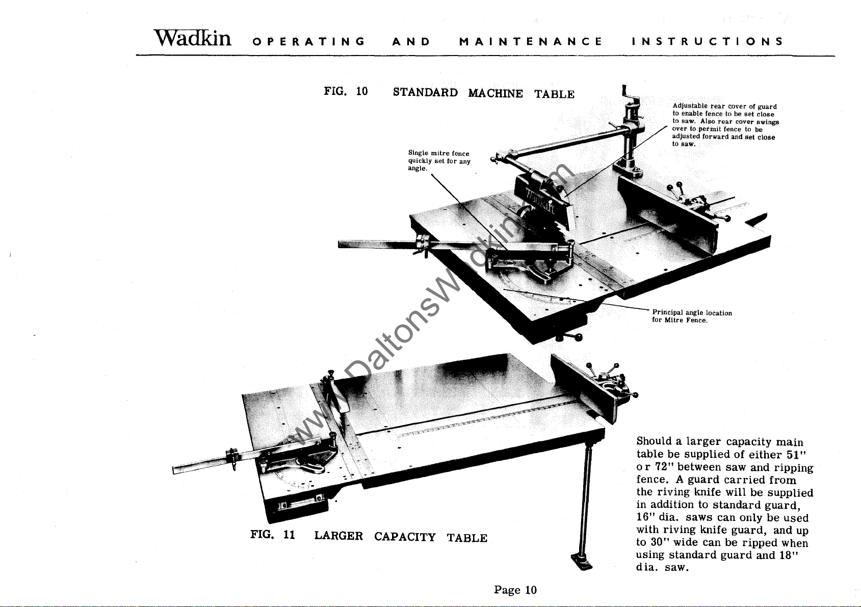
FIG. 10
STANDARD
Single
mitre
set
fence
for any
quickly
angle.
MACHINE
TABLE
Adjustable
to enable fence to
to saw. Also
over
adjusted
to
saw.
Principal
for
Mitre
rear
rear
to
permit
fence to be
forward
angle location
Fence.
cover
be
cover
and
set
set
of
guard
close
swings
close
FIG.
11
LARGER CAPACITY TABLE
Page
10
Should a
table
or
72" between
fence. A guard
the riving knife
larger
be
supplied
capacity
of
either
saw
and ripping
carried
will
be
main
51"
from
supplied
in addition to standard guard,
16" dia.
saws
can only
be
used
with riving knife guard, and
to 30" wide can
using standard guard and
dia.
saw.
be
ripped when
18"
up
 Loading...