

OPERATING
AND
INSTRUCTION
MANUAL FOR
HIGH
SPEED ROUTER TYPE
LS
www.wadkin.com
info@wadkin.com
Wadkin
HIGH
SPEED
ROUTER
TYPE
L.
S.
PRINCIPAL DIMENSIONS
AND
CAPACITIES
:-
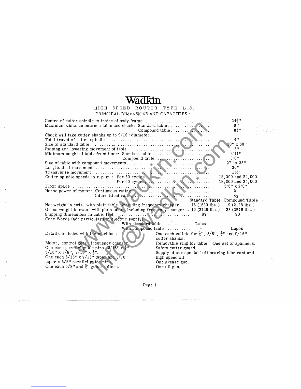
Centre
of
cutter
spindle
to
inside
of body
frame
...........................
.
Maximum
distance
between
table
and chuck:
Standard
table
.................
.
Compound
table
................
.
Chuck
will
take
cutter
shanks
up
to
9/16"
diameter.
Total
travel
of
('utter
spindle
...........................................
.
Size
of
standard
table
.,
.... _ ..........................
_
...............
.
Raising
and
lowering
movement
of
table
.................................
.
Minimum
height
of
table
from
floor:
Standard
table
........................
.
Compound table
.......................
.
Size
of
table
with compound
movements
...........
,
.......................
.
Longitudinal
movement
.................................................
.
Transverse
movement
.................................................
.
24~"
9"
8~"
4"
30" x 30"
5"
2'11"
3'
A"
27" x 33"
30 "
15t"
Cutter
spindle
speeds
in
r.
p.
m.:
For
50
cycles
...........................
.
For
60
cycles,
..........................
.
Floor
space
...........................................................
.
18,000
and
24,000
18,000
and
25,000
5'6" x 2'6"
Horse
power
of
motor:
Continuous
rating
.................................
.
Intermittent
rating
................................
.
Net
weight
in
cwts.
with
plain
table,
including
frequency
changer
....
Gross
weight
in
cwts.
with
plain
table,
including
frequency
changer
..
Shipping
dimensions
in
cubic
feet
...............................
.
Code
Words
(add
particulars
of
electric
supply)
Standard
Table
15(1680
lbs.
)
19
(2128
lbs.
)
97
With
standard
table
..........
"
Labas
2
8t
Compound
Table
19 (2128
Ibs.
)
23
(2576
lbs.
)
90
With compound
table
..........
Lupos
Details
included
with the
machines
Motor,
control
gear,
frequency
changer.
One
each
parallel
guide
pins,
3/16"
x t",
5/16"
X
3/8",
7/16"
x
~".
One
each
5/16"
x
7/16"
taper
and 3/16"
taper
x
5/8"
parallel
guide
pins.
One
each
5/8"
and
t"
guide
rollers.
One
each
collets
for
t",
3/8",
~"and
9/16"
cutter
shanks.
Removable
ring
for
table.
One
set
of
spanners.
Safety
cutter
guard.
Supply of
our
special
ball
bearing
lubricant
and
high
speed
oil.
One
grease
gun.
One oil gun.
Page
1
www.wadkin.com
info@wadkin.com
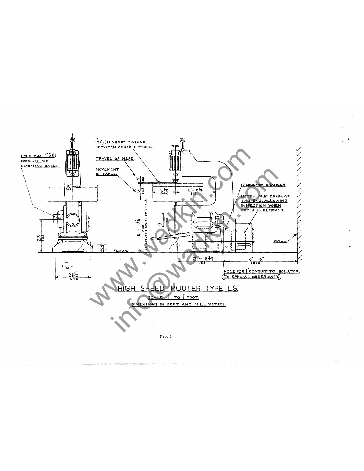
HOLI!.
FOR
r~5)
CONDUIT
FOR
INCOMING
CABLE..
•
rt)
ru
'"
Y+(5)MINIMUM
DISTANCE.
BETWEEN
CHUcK
It
TAaL.E..
TRAVE.L
of
MoVEME.NT
OF
T'ABLE.
FL.OOR.
•
lI)
It)nJ
.j
..J
ID
~
L
o
~~
~
-
I!)
-
O;j
I
~
J:
C\J
r
:J
r
Z
r
WALL.
3' -,"
106
HOLE.
FOJ\
(CONDUIT
"T"Q
lS01..ATOR.
ero
SPECIAL
Q.RQf.R
ONLY)
HIGH SPEED ROUTER. TYPE LS.
SCAL.E.
J"
TO I FOOT.
CIME.NSIONS
IN
FEE.T
AND
MIL.L.IMf.TRES.
Page
2
www.wadkin.com
info@wadkin.com
INSTALLATION
The
machine
is
despatched
from
the
Works
with
all
bright
surfaces
greased
to
prevent
rusting.
This
must
be
removed
by
applying a cloth
damped
with
paraffin
or
turpentine.
FOUNDATIONS.
Four
5/8"
diameter
foundation
bolts
must
be
used
to
bolt
machine
down to
the
floor.
Foundation
bolts
are
not
supplied
by
Wadkin Ltd.
unless
specially
ordered.
"Rag"
type
holding
down
bolts
may
be
used.
If
mill
floor
consists
of
from
4"
to
6"
solid
concrete
no
special
foundation
is
nec-
essary.
Cut out in
concrete
4
f1
to 6
f1
square
holes
and
fill
in
and
grout
with
liquid
cement
after
machine
has
been
carefully
levelled.
E LE
CTRICAL
CONNE CTIONS
See
Page
65
for
details
and
connection
diagram.
IMPOR
TANT:-
The
frequency
changer
must
NOT
be
bolted
down
but
placed
inside
the
main
frame
after
the
machine
is
finally
fixed. Make
sure
that
the
surface
is
level
and
smooth
to
enable
the
frequency
changer
to
be
readily
withdrawn
Alignment
of
Table
Pin
to
Spindle. A Setting
Arbor
is
supplied
for
checking
this
alignment.
The
table
is
not dowe
lled
to the
vertical
slide,
so
that
it
can
be
reset
from
time
to
time
with
the
head.
Fit
the
setting
arbor
in the
spindle
and
lower
head
to
table.
Now
slacken 4 screws
securing
table
to
vertical
slide
and
float
table
horizontally
until
the
arbor
in
spindle
enters
pin
hole
in
table.
Relevel
table
securing
screws,
and
remove
arbor
from
spindle.
Page
3
www.wadkin.com
info@wadkin.com
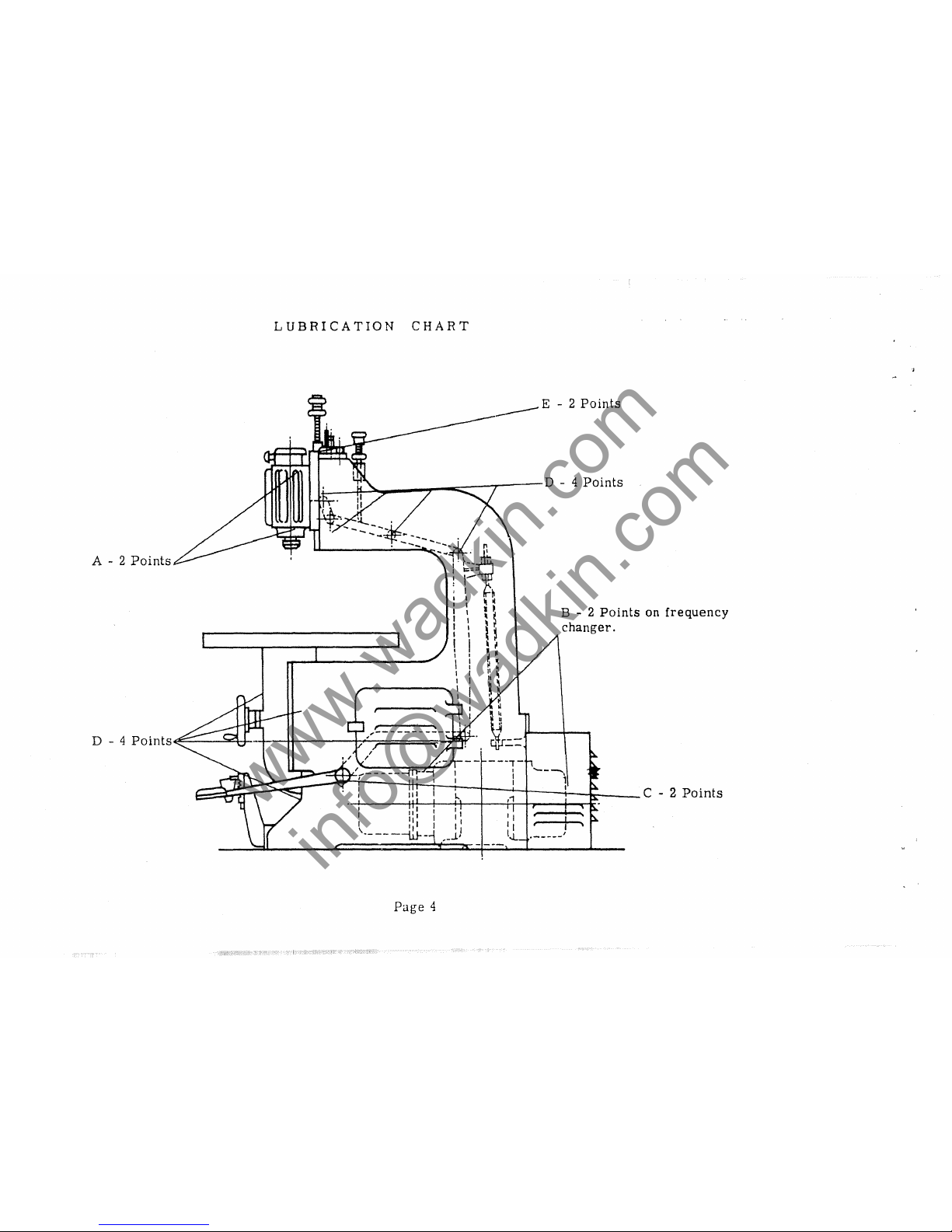
LUBRICATION
CHART
.i-_~~_--r-;;;;;::::=-T--D
- 4
Points
A - 2
Points
-.:.
~~'-~~
I
1:;=
! 1-
; 1
~
::
~ ~
I I •
~
I I
~"
I:
H
I I
~
~
\ I
;-
\
~ ~ ~
I I
,q
I 1 h
~
~---------:
I
~
I i
~
D - 4
Po
ints~~-~tJ-'-r-tt----i7"-,====;P-;~
it=-=
11
I I I I
11' I
I,
l
I11
I
11
-------I.iJ--
__
J..
Page
4
B-2
Points
on
frequency
changer.
,
..-
____
1
www.wadkin.com
info@wadkin.com
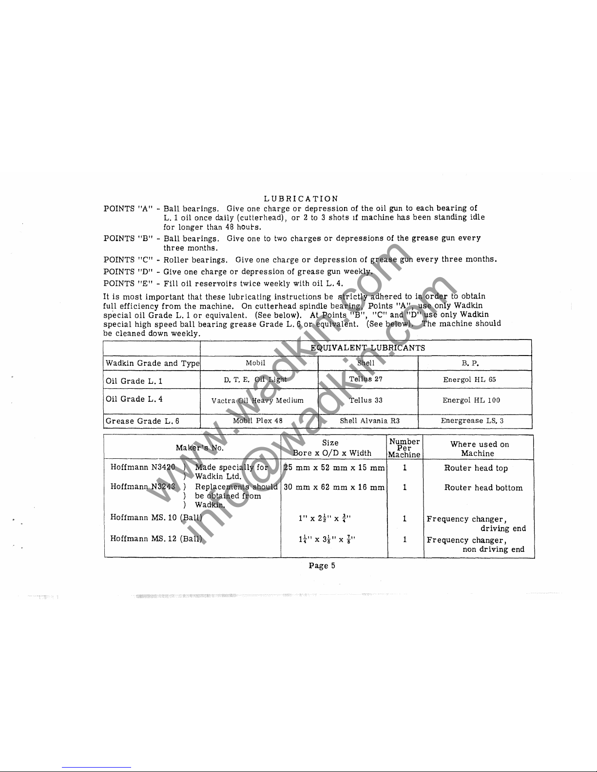
LUBRICATION
POINTS
"A" -Ball
bearings.
Give
one
charge
or
depression
of
the
oil
gun to
each
bearing
of
L.l
oil
once
daily
(cutterhead),
or
2 to 3
shots
If
machine
has
been
standing
idle
for
longer
than 48
houbs.
POINTS
"B" -Ball
bearings.
Give
one
to two
charges
or
depressions
of
the
grease
gun
every
three
months.
POINTS
"Cif -
Roller
bearings.
Give
one
charge
or
depression
of
grease
gun
every
three
months.
POINTS
"D" -
Give
one
charge
or
depression
of
grease
gun
weekly.
POINTS
"E"
-
Fill
oil
reservoirs
twice
weekly
with
oil
L.
4.
It
is
most
important
that
these
lubricating
instructions
be
strictly
adhered
to
in
order
to
obtain
full
efficiency
from
the
machine.
On
cutterhead
spindle
bearing,
Points
"A",
use
only
Wadkin
special
oil
Grade
L. 1
or
equivalent.
(See
below).
At
Points
"B",
"Cif
and
"DI'
use
only
Wadkin
special
high
speed
ball
bearing
grease
Grade
L. 6 or
equivalent.
(See
below).
The
machine
should
be
cleaned
down
weekly.
EQUIVALENT
LUBRICANTS
Wadkin
Grade
and
Type
MobU
Shell
B.
P.
Oil
Grade
L.
1
D.
T.
E.
Oil
Light
Tellus
27
Energol
HL
65
Oil
Grade
L.
4
Vactra Oil Heavy Medium
Tellus
33
Energol
HL
100
Grease
Grade
L.
6
Mobil
Flex
48
Shell
Alvania R3
Energrease
LS, 3
Maker'S
No.
Size
Number
Where
used
on
Per
Bore
x
OlD
x Width
Machine
Machine
Hoffmann
N3420
)
Made
specially
for
25
mm
x
52
mm
x 15
mm
1
Router
head
top
)
Wadkin
Ltd.
Hoffmann
N3243
\
Replacements
should
30
mm
x
62
mm
x 16
mm
1
Router
head
bottom
J
,
be
obtained
from
J
)
Wadkin.
Hoffmann
MS. 10
(Ball)
1"x2%"
x t"
1
Frequency
changer,
driving
end
Hoffmann
MS. 12
(Ball)
It"
x
3i"
x t"
1
Frequency
changer,
non
driving
end
Page
5
www.wadkin.com
info@wadkin.com

HIGH
SPEED
ROUTER
MODEL
L.
S.
-
THE
HEAD
TYPE
Q
Start
and
stop
buttons
D
Two
speed
switch.
A.
E
c
B
Fig. 1
H
G
K
___
J
~~~----------------
__
M
Page
6
Fine
screw
adjustment
to
head.
www.wadkin.com
info@wadkin.com
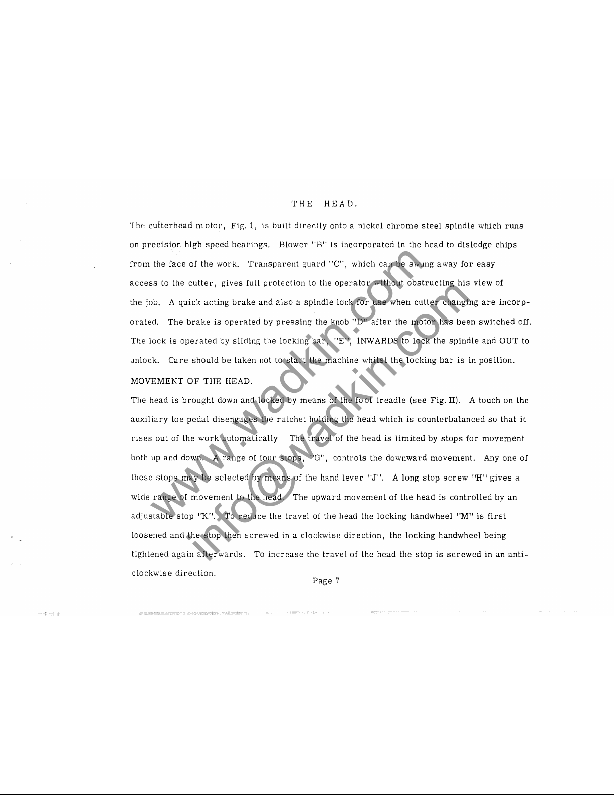
THE
HEAD.
The
cuEterhead
motor,
Fig,
1,
is
built
directly
onto a
nickel
chrome
steel
spindle
which
runs
on
precision
high
speed
bearings.
Blower
"B"
is
incorporated
in the
head
to
dislodge
chips
from
the
face
of the work.
Transparent
guard
"C",
which
can
be
swung
a way
for
easy
access
to the
cutter,
gives
full
protection
to
the
operator
without
obstructing
his
view
of
the job. A
quick
acting
brake
and
also a spindle
lock
for
use
when
cutter
changing
are
incorp-
orated.
The
brake
is
operated
by
pressing
the knob "Dti
after
the
motor
has
been
switched
off.
The
lock
is
operated
by
sliding
the
lOCking
bar,
tiE
tI
, INWARDS to
lock
the
spindle
and
OUT
to
unlock.
Care
should
be
taken
not to
start
the
machine
whilst
the
locking
bar
is
in
position.
MOVEMENT
OF
THE
HEAD.
The
head
is
brought
down
and
locked
by
means
of the fa
at
treadle
(see
Fig.
II). A
touch
on
the
auxiliary
toe
pedal
disengages
the
ratchet
holding the
head
which
is
counterbalanced
so
that
it
rises
out
of the
work
automatically
The
travel
of the
head
is
limited
by
stops
for
movement
both
up
and
down. A
range
of
four
stops,
"G",
controls
the
downward
movement.
Anyone
of
these
stops
may
be
selected
by
means
of the hand
lever
"J",
A
long
stop
screw
"H"
gives
a
wide
range
of
movement
to the head.
The
upward
movement
of
the
head
is
controlled
by
an
adjustable
stop
"K",
To
reduce
the
travel
of
the
head the
locking
handwheel
"M"
is
first
loosened
and
the
stop
then
screwed
in a
clockwise
direction,
the
locking
handwheel
being
tightened
again
afterwards.
To
increase
the
travel
of the
head
the
stop
is
screwed
in
an
anti-
clockwise
direction.
Page
7
www.wadkin.com
info@wadkin.com
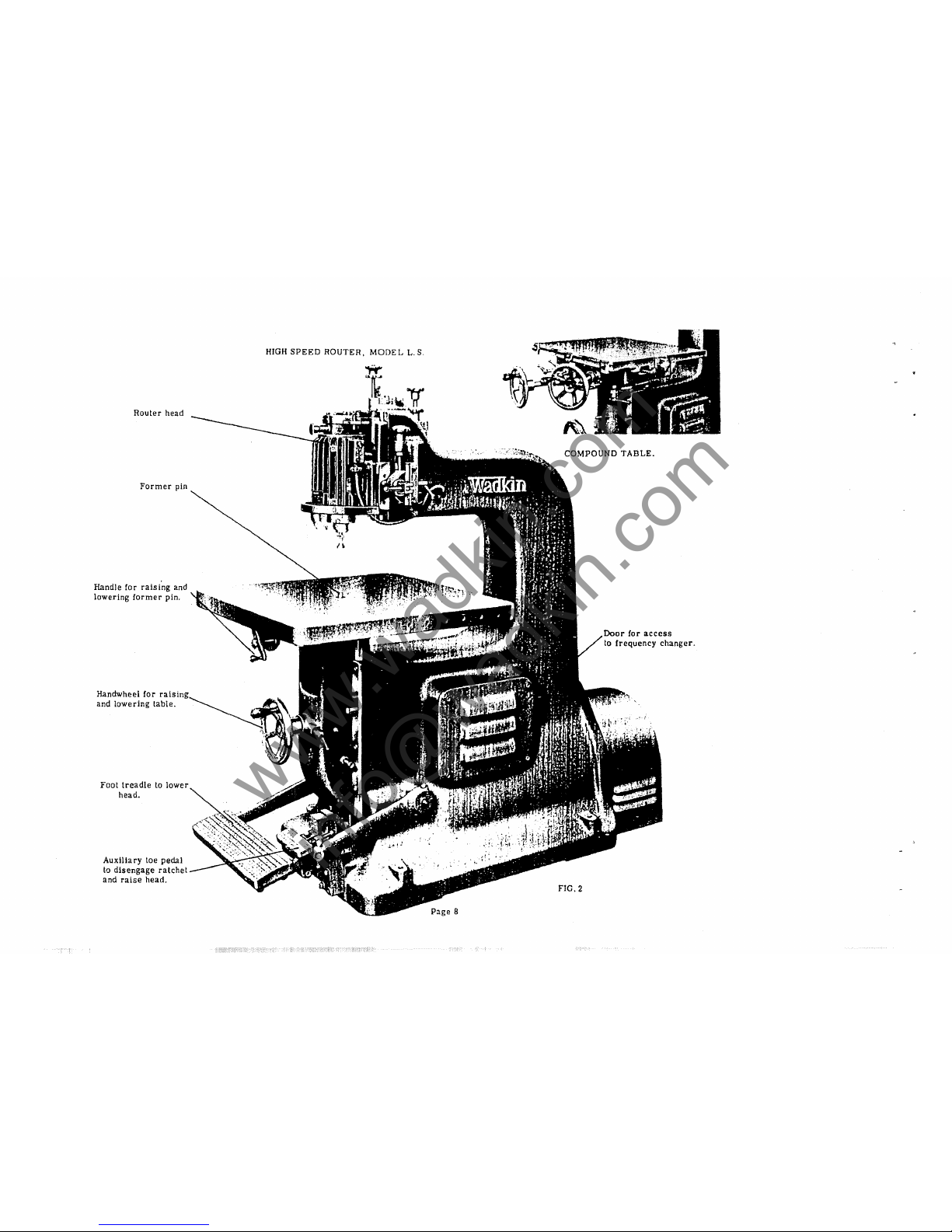
Router
head
Former
pin
Handle for
raising
and
lowering
former
pin.
Handwheel
for
raj
and
lowering
table.
Foot
treadle
to
lower
head.
Auxiliary
toe
pedal
to
disengage
ratchet
and
raise
head.
HIGH
SPEED
ROUTER,
MODEL
L.S.
COMPOUND
TABLE.
Door
for
access
to
frequency
changer.
FIG.2
www.wadkin.com
info@wadkin.com
c
B
aAL.L. PL.UNGf:.R GIves
THRe~
posrrloNS
TO
F01\Ml!./\
PIN.
I
E
D
Flg.4
TABLE.
J'
7'8
MAXIMUM
HE.IGHT
OF
FO/\Me.t>.
PIN.
3"
YJ6
MEOIUM
POSITION
OF
FORMe.t>.
PIN.
fOI\ME.R.
PIN
6SSf:M5LY
IN
THE.
COMPOUND
Tt'l8LI!..
FI(3.4.
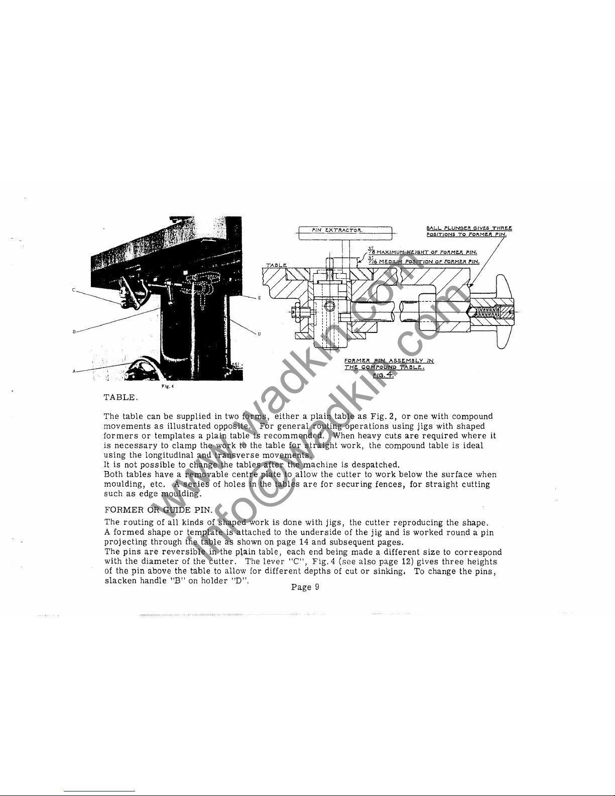
The
table
can
be
supplied
in two
forms,
either a plain
table
as
Fig.
2,
or
one
with
compound
movements
as
illustrated
opposite.
For
general
routing
operations
using
jigs
with
shaped
formers
or
templates a plain
table
is
recommended.
When
heavy
cuts
are
required
where
it
is
necessary
to
clamp
the
work
to the
table
for
straight
work,
the
compound
table
is
ideal
using
the
longitudinal
and
transverse
movements.
It
is
not
possible
to
change
the
tables
after
the
machine
is
despatched.
Both
tables
have a removable
centre
plate
to
allow
the
cutter
to
work
below
the
surface
when
moulding,
etc. A series
of
holes
in the
tables
are
for
securing
fences,
for
straight
cutting
such
as
edge
moulding.
FORMER
OR GUIDE
PIN.
The
rO\lting
of
all
kinds
of
shaped
work
is
done
with
jigs,
the
cutter
reproducing
the
shape.
A
formed
shape
or
template
is
attached
to
the
underside
of
the
jig
and
is
worked
round a pin
proj
ecting
through
the
table
a$
shown
on
page
14
and
subsequent
pages.
The
pins
are
reversible
in the
plain
table,
each
end
being
made a different
size
to
correspond
with
the
diameter
of
the
cutter.
The
lever
"C",
Fig.4
(see
also
page
12)
gives
three
heights
of
the
pin
above
the
table
to
allow
for
different
depths
of
cut
or
sinking.
To
change
the
pins,
slacken
handle
"B"
on
holder
"D".
Page
9
www.wadkin.com
info@wadkin.com
The
pins
are
not
reversible
in the compound
table
but
are
quickly
detachable
by
the
key
prov-
ided and
as
shown
in
the
illustration
Fig.
4.
The
three
positIOns of the
pin
are
controlled
by
ball
plunge
r.
The
following
former
pins
and
rollers
can
be
supplied
:-
Pins
for
Plain
Table
3/16"
-
tIt
5/16"
- i"
7/16"
-
~"
Double
ended
and
Reversible
Pins
for Compound
Table
3/1
6"
1.
"
5/16"
1.
t t
1..
, t
, 4 , , 8 , 2
These
are
single
ended
and
not
reversible.
THE ROUTER HEAD
is
shown in
section
on
page
11.
Rollers
for
both
types
of
pin
~II
1."
111
I"
11.11
11.11
1
1
"
11.11
S,ot,S,
,8,4,8,2
All
rollers
are
arranged
to
fit
the
~"
size
pins
only.
The
bearings
are
lubricated
by a
patented
system
of
oil
mist
lubrication
and
therefore
it
is
important
to
use
the
oil
and
to
lubricate
the
bearings
to
instructions
given
on
page
5.
Since
the
introduction
of
our
patented
system,
the
special
high
speed
ball
bearings
(which
must
be
purchased
from
Wadkin
Ltd.
) have
given
exceptional
performance,
but
as
no
guarantee
can
be
given
against
bearing
failure
which
could
be
attributable
to
over
lubrication
or
other
causes,
it
is
recommended
that
the Head
is
returned
to
us
for
repair.
We
have a Service
Department
where
the
work
is
undertaken
with
the
minimum
delay.
Where
machines
are
shipped
abroad
this
service
arrangement
cannot
economi-
cally
be
given.
Under
these
circumstances'
a
description
of how to
dismantle
the Head
is
given on
page
11.
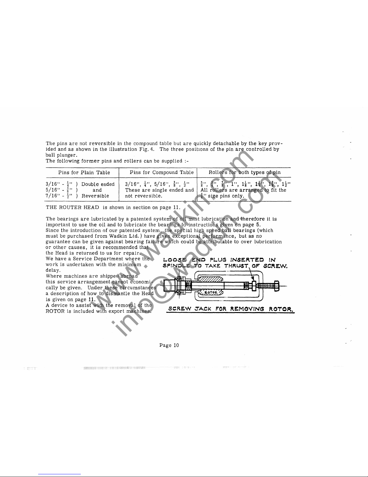
A
device
to
assist
with
the
removal
of the
ROTOR
is
included
with
export
machines.
l..OOSE
ENC
PL.UG
INSERTEC
rN
SPINOLE:
TO
TAKE
"H~UST
OF
SCRE.W.
SCRE.W
JACK
rOR
RE:MOV1NG
ROTOR.
Page
10
www.wadkin.com
info@wadkin.com
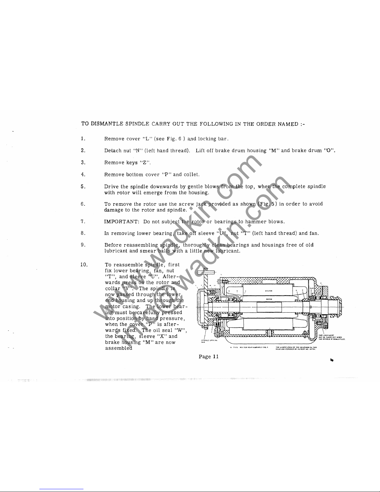
TO
DISMANTLE
SPINDLE
CARRY
OUT
THE FOLLOWING IN THE ORDER NAMED -
1.
Remove
cover
ilL"
(see
Fig.
6 )
and
locking
bar.
2.
Detach
nut
"N"
(left
hand
thread).
Lift
off
brake
drum
housing
"M"
and
brake
drum
"a".
3.
Remove
keys
"Z".
4.
Remove
bottom
cover
"P"
and
collet.
5.
Drive
the
spindle
downwards
by
gentle
blows
from
the top,
when
the
complete
spindle
with
rotor
will
emerge
from
the
housing.
6. To
remove
the
rotor
use
the
screw
jack
provided
as
shown
(Fig.
5)
in
order
to
avoid
damage
to the
rotor
and
spindle.
7.
IMPORTANT:
Do
not
subject
the
rotor
or
bearings
to
hammer
blows.
8. In
removing
lower
bearing,
take
off
sleeve
"U",
nut
"T"
(left
hand
thread)
and
fan.
9.
Before
reassembling
spindle,
thoroughly
clean
bearings
and
housings
free
of
old
lubricant
and
smear
balls
with a little
new
lubricant.
10.
To
reassemble
spindle,
first
fix
lower
bearing,
fan, nut
1fT",
and
sleeve
"U".
After-
wards
press
on the
rotor
and
collar
"V".
The
spindle
is
now
passed
through
the
lower
end
housing
and
up
through
the
motor
casing.
The
lower
bear-
ing
must
be
carefully
pressed
into
position
by
hand
pressure,
when
the
cover
"P"
is
after-
wards
fixed.
The
oil
seal
"W",
the
bearing,
sleeve
"X"
and
brake
housing
"M"
are
now
assembled
Page
11
Q
T'rrr
1'10\
TUt
I'IU.b
ollOill"IIL'I'
fIG.'
'rrt[
LU81'1I('Ano".
or
THr
lI.f.:olRIIiGII
01'1
TMIS
"lA.C
"JI[
COYUI1D
IT
PATt.flfT
NO.
un
...
www.wadkin.com
info@wadkin.com
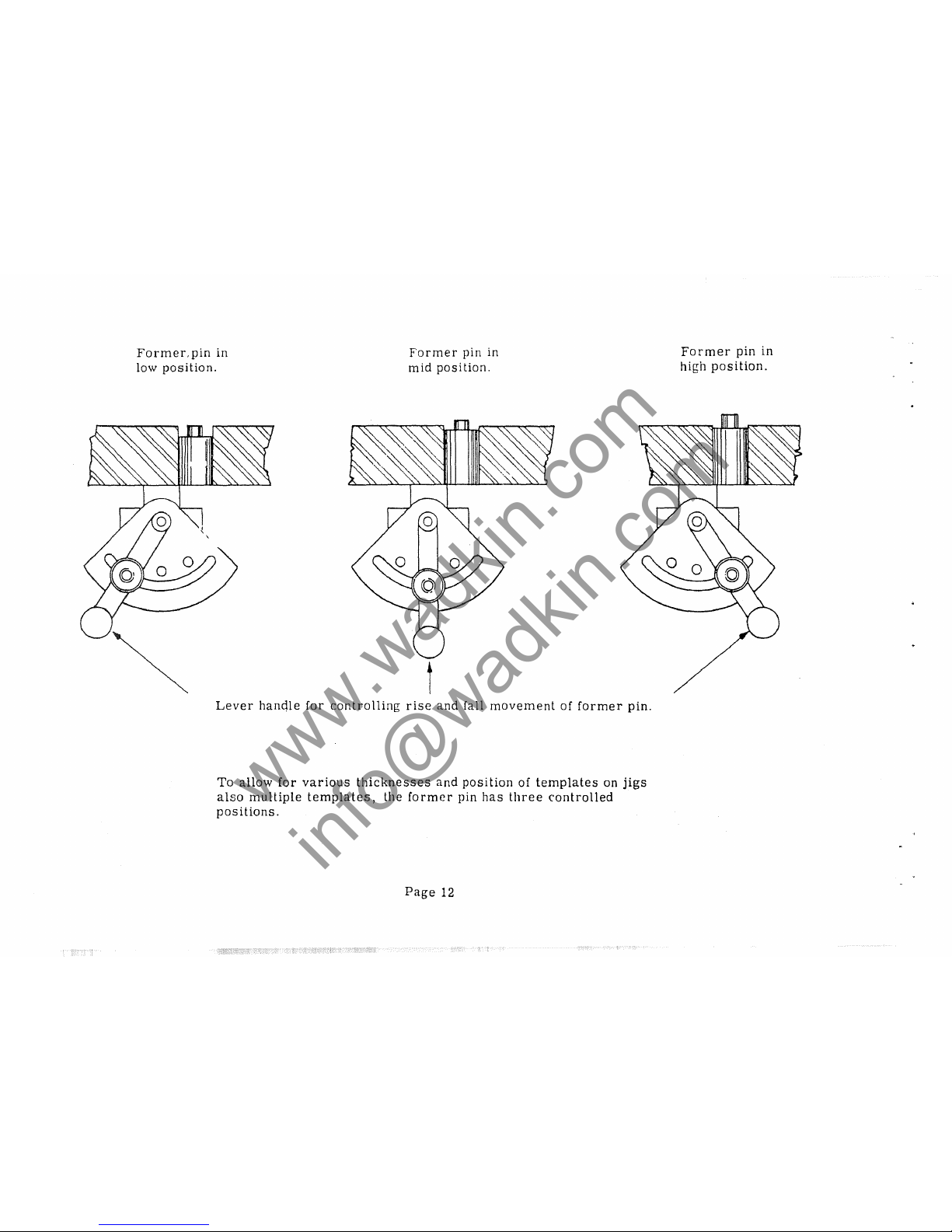
Former,
pin
in
low
position.
Former
pin in
mid
position.
t
Lever
hancHe
for
controlling
rise
and
fall
movement
of
former
pin.
To
allow
for
various
thicknesses
and
position
of
templates
on
jigs
also
multiple
templates,
the
former
pin
has
three
controlled
positions.
Page
12
Former
pin
in
hi~h
position.
www.wadkin.com
info@wadkin.com
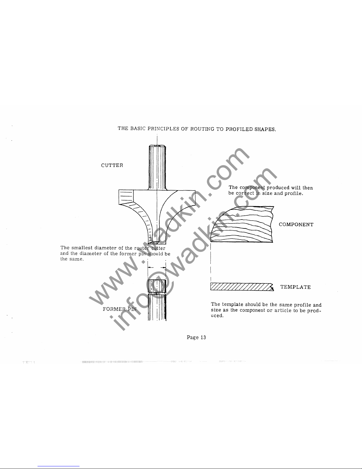
THE
BASIC
PRINCIPLES
OF
ROUTING
TO
PROFILED
SHAPES.
CUTTER
The
smallest
diameter
of the
router
cutter
and
the
diameter
of
the
former
pin
should
be
the
same.
_1
.
I
I
I
I I
I
~
FORMER
PIN
I
Page
13
The
component
produced
will
then
be
correct
in
size
and
profile.
COMPONENT
The
template
should
be
the
same
profile
and
size
as
the
component
or
article
to
be
prod-
uced.
www.wadkin.com
info@wadkin.com
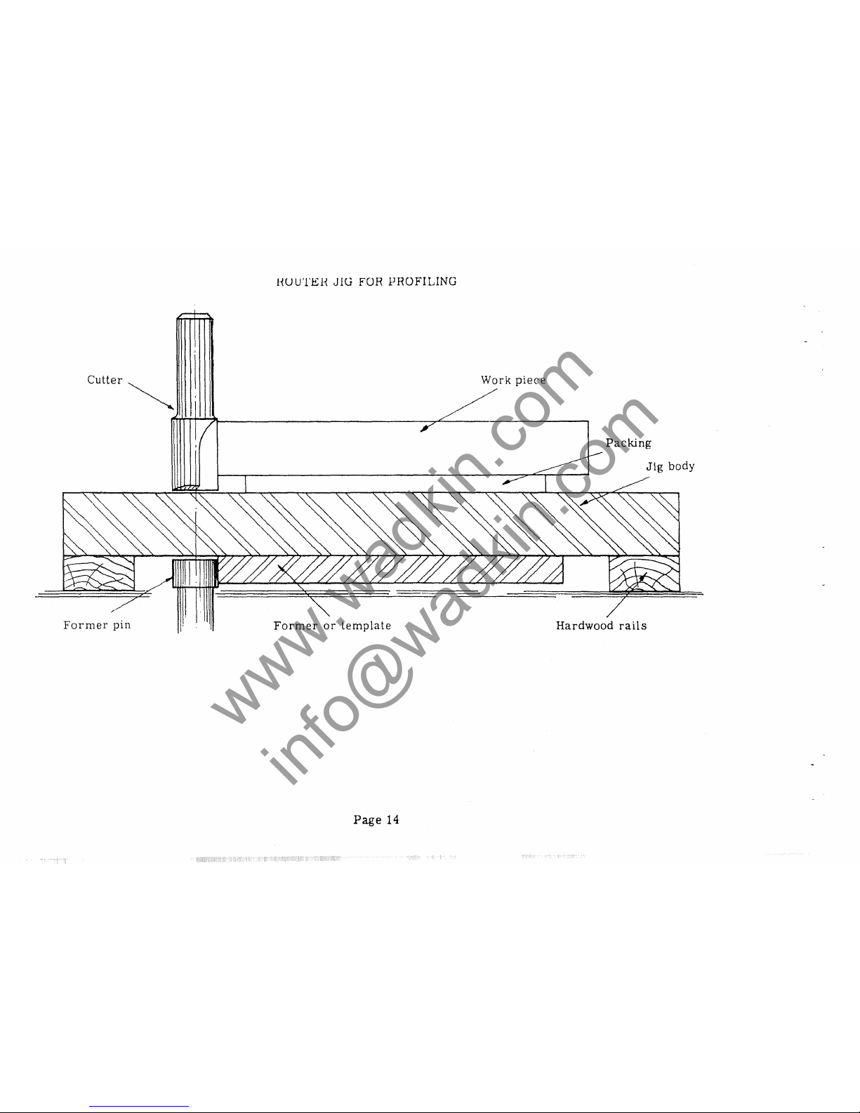
HU
UTEH
J lU FOR
1?
ROFILING
cutter~
Work
piece
Packing
Jig
body
Former
pin
Former
or
template
Hardwood
rails
Page
14
www.wadkin.com
info@wadkin.com
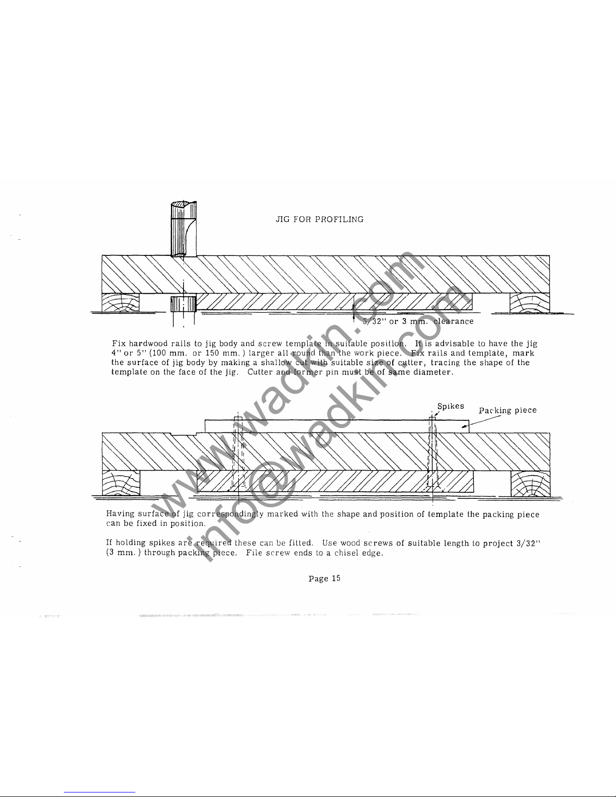
JIG
FOR
PROFILING
,
3/32"
or 3 mm.
clearance
Fix
hardwood
rails
to
jig
body
and
screw
template
in
suitable
position.
It
is
advisable
to
have
the
jig
4"
or
5"
(100
mm.
or
150
mm. ) larger
all
round
than
the
work
piece.
Fix
rails
and
template,
mark
the
surface
of
jig
body
by
making a shallow
cut
with
suitable
size
of
cutter,
tracing
the
shape
of
the
template
on
the
face
of
the
jig.
Cutter
and
former
pin
must
be
of
same
diameter.
Spikes
"
Packing
piece
Having
surface
of
jig
corresponc;lingly
marked
with
the
shape
and
position
of
template
the
packing
piece
can
be
fixed
in
position.
If
holding
spikes
are
required
these
can
be
fitted.
Use
wood
screws
of
suitable
length
to
project
3/32"
(3
mm. ) through
packing
piece.
File
SrT8W
ends
to a
chisel
edge.
Page
15
www.wadkin.com
info@wadkin.com
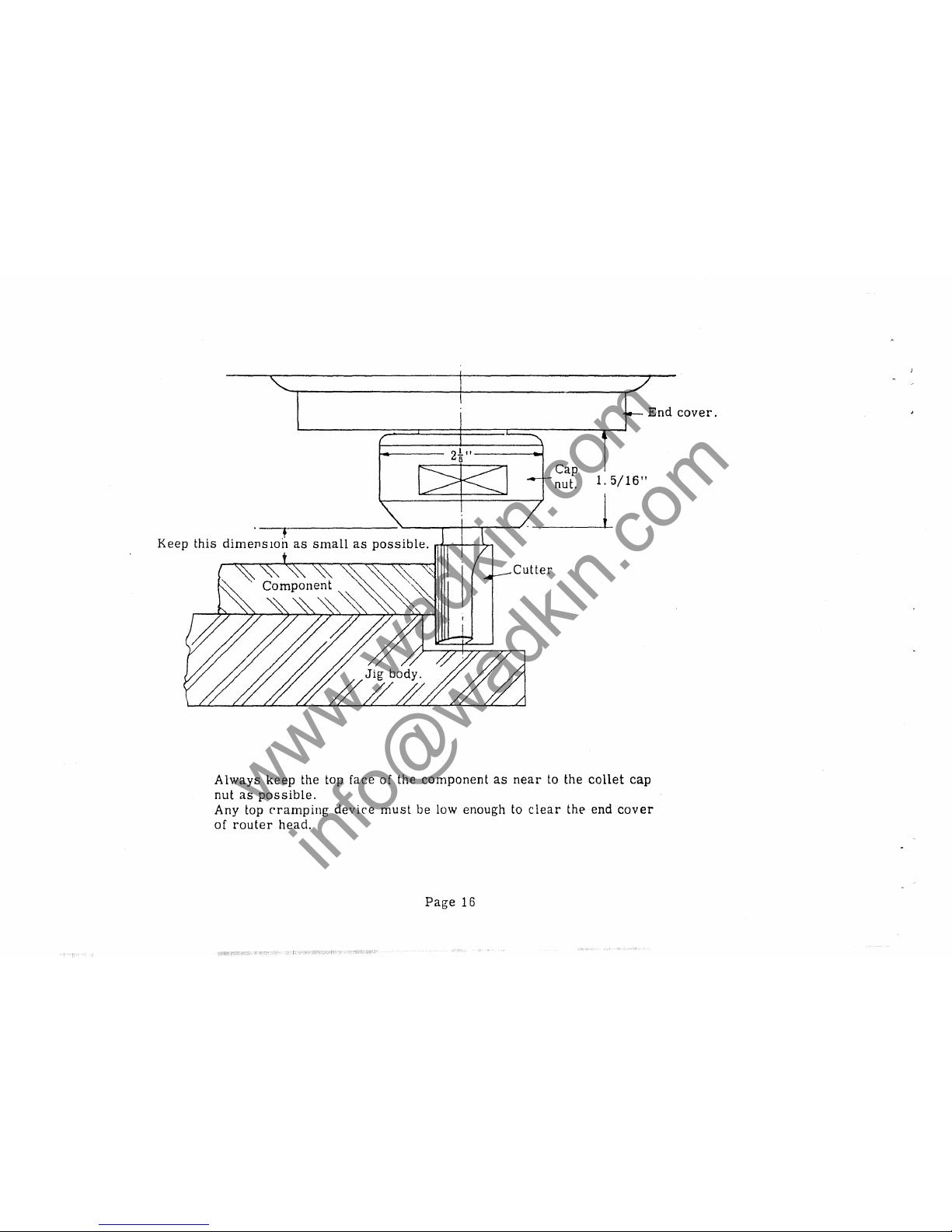
+
Keep
this
dimenSIOn
as
small
as
possible
.
..4-
____
--1.-.
Cutter
Cap
1.
5/16"
nut.
1
End
cover.
Always
keep
the top face of the
component
as
near
to the
collet
cap
nut
as
possible.
Any top
cramping
device
must
be low enough to
clear
the end
cover
of
router
head.
Page
16
www.wadkin.com
info@wadkin.com
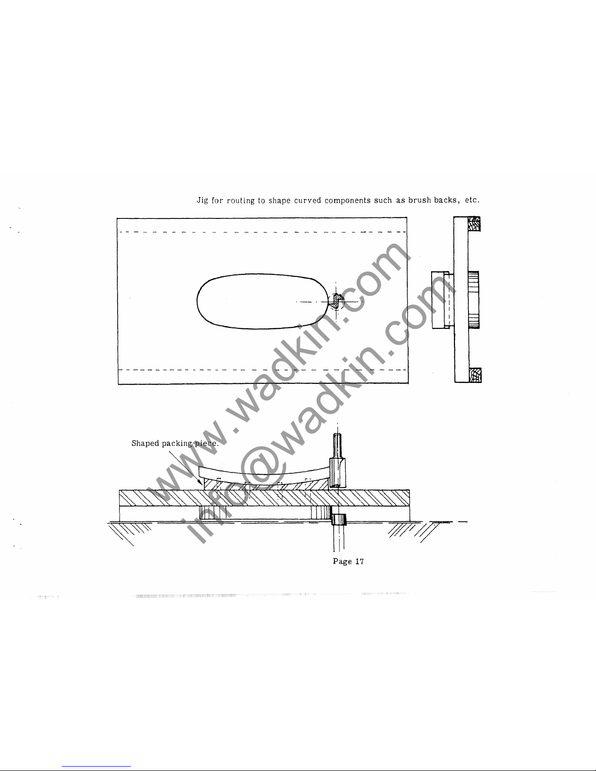
Jig
for
routing
to shape
curved
components
such
as
brush
backs,
etc.
Shaped
packing
piece.
Page
17
www.wadkin.com
info@wadkin.com
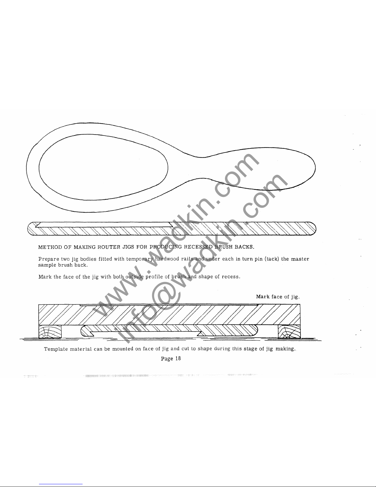
METHOD
OF
MAKING
ROUTER
JIGS
FOR
PRODUCING
RECESSED
BRUSH BACKS.
Prepare
two
jig
bodies
fitted
with
temporary
hardwood
rails
and
under
each
in
turn
pin
(tack)
the
master
sample
brush
back.
Mark
the
face
of
the
jig
with
both
outside
profile
of
brush
and
shape
of
recess.
Mark
face
of
jig.
Template
material
can
be
mounted
on
face
of
jig
and
cut
to
shape
during
this
stage
of
jig
making.
Page
18
www.wadkin.com
info@wadkin.com
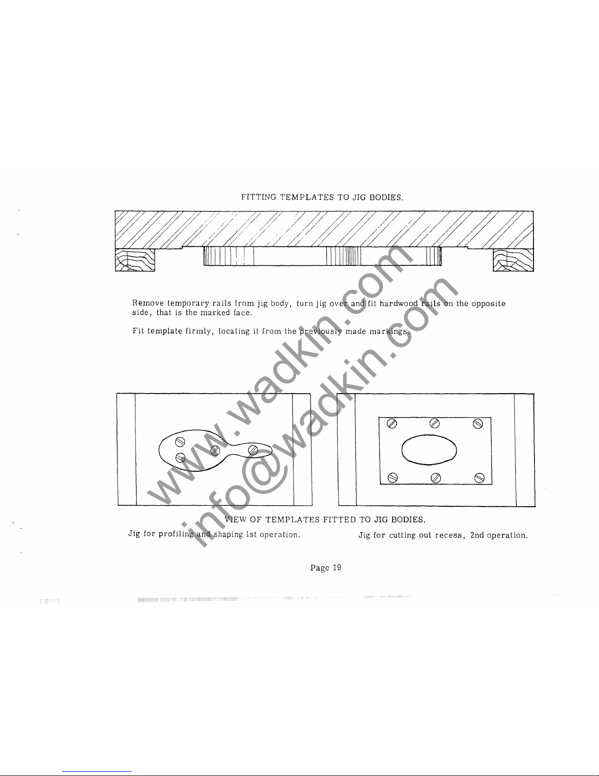
FITTING
TEMPLATES
TO JIG BODIES.
Remove
temporary
rails
from
jig
body,
turn
jig
over
and fit
hardwood
rails
on
the
opposite
side,
that
is
the
marked
face.
Fit
template
firmly,
locating
it
from
the
previously
made
markings.
0
0
6)
0
§
0
e
VIEW
OF
TEMPLATES
FITTED
TO
JIG
BODIES.
Jig
for
profiling
and
shaping
1st
operation.
Jig
for
cutting
out
recess,
2nd
operation.
Page
19
www.wadkin.com
info@wadkin.com
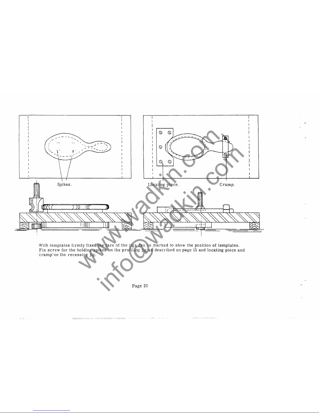
....
~
-
-'
Spikes.
Locating
piece.
Cramp.
With
templates
firmly
fixed
the
face
of
the
jigs
can
be
marked
to
show
the
position
of
templates.
Fix
screw
for
the
holding
spikes
on
the
profiling
jig
as
described
on
page
15
and
locating
piece
and
cramp'on
the
recessing
jig.
Page
20
www.wadkin.com
info@wadkin.com
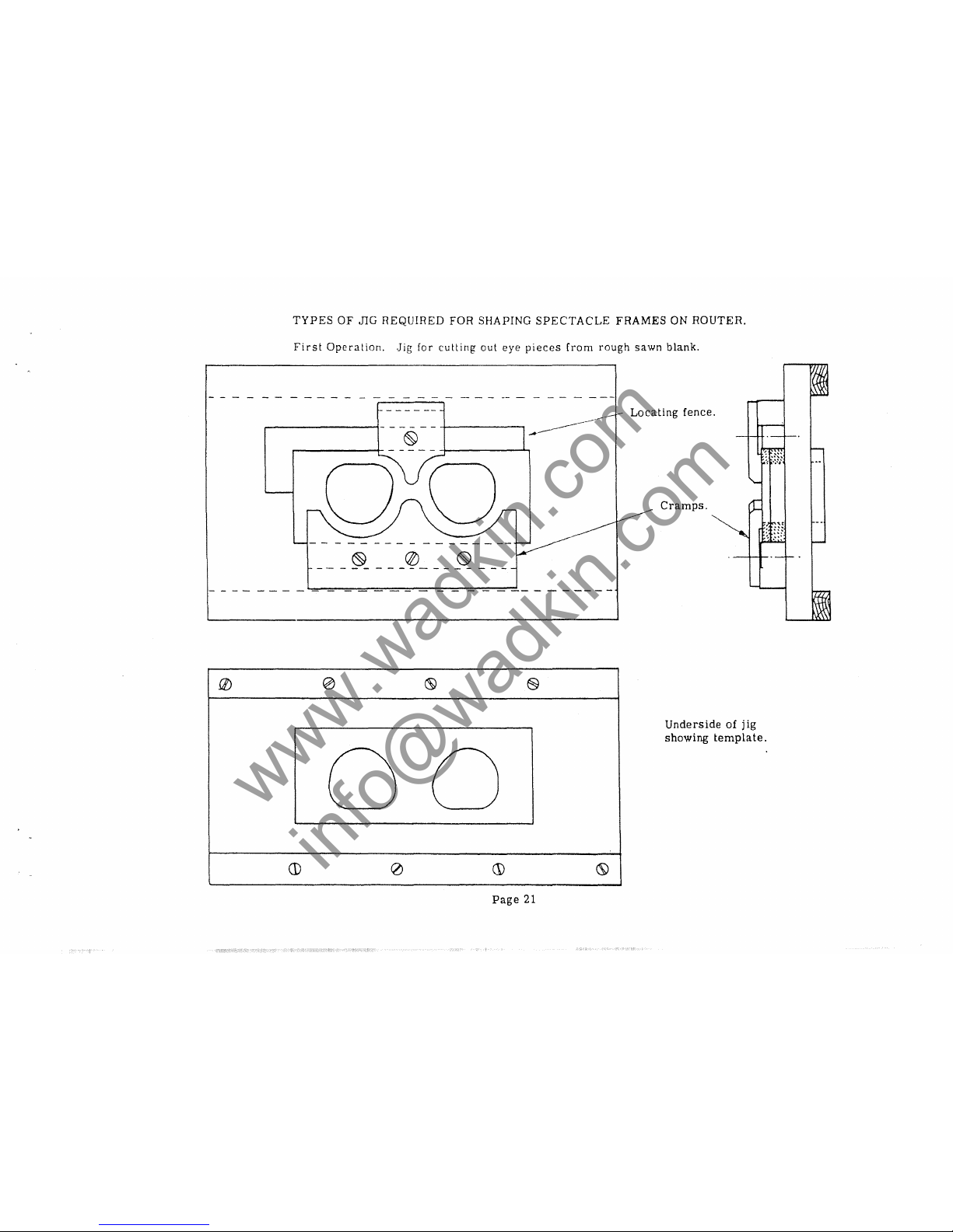
TYPES
OF
JIG
REQUIRED
FOR
SHAPING
SPECTACLE
FRAMES
ON
ROUTER.
First
Operation.
.Jig
for
cutting
out
eye
pieces
from
rough
sawn
blank.
------------------
..--------\-
- - - - -
+-----,
--------~-
@
r------_I_
- - - - -
-1------"-1
0
<8
(§)
§
0
0
CD
0
(j)
(S)
Page
21
Locating
fence .
Cramps.
Underside
of
jig
showing
template.
www.wadkin.com
info@wadkin.com

- - - - - - - - - - - - - - - - - - - - -
--
- - - - - - - - - - - -
-----
.
~.
'\-;2J
~age
22
Jig
for
shaping
outsides
of
spectacle
frames.
Locating
off
previously
cut
eye-pieces
.
www.wadkin.com
info@wadkin.com
--
...
®
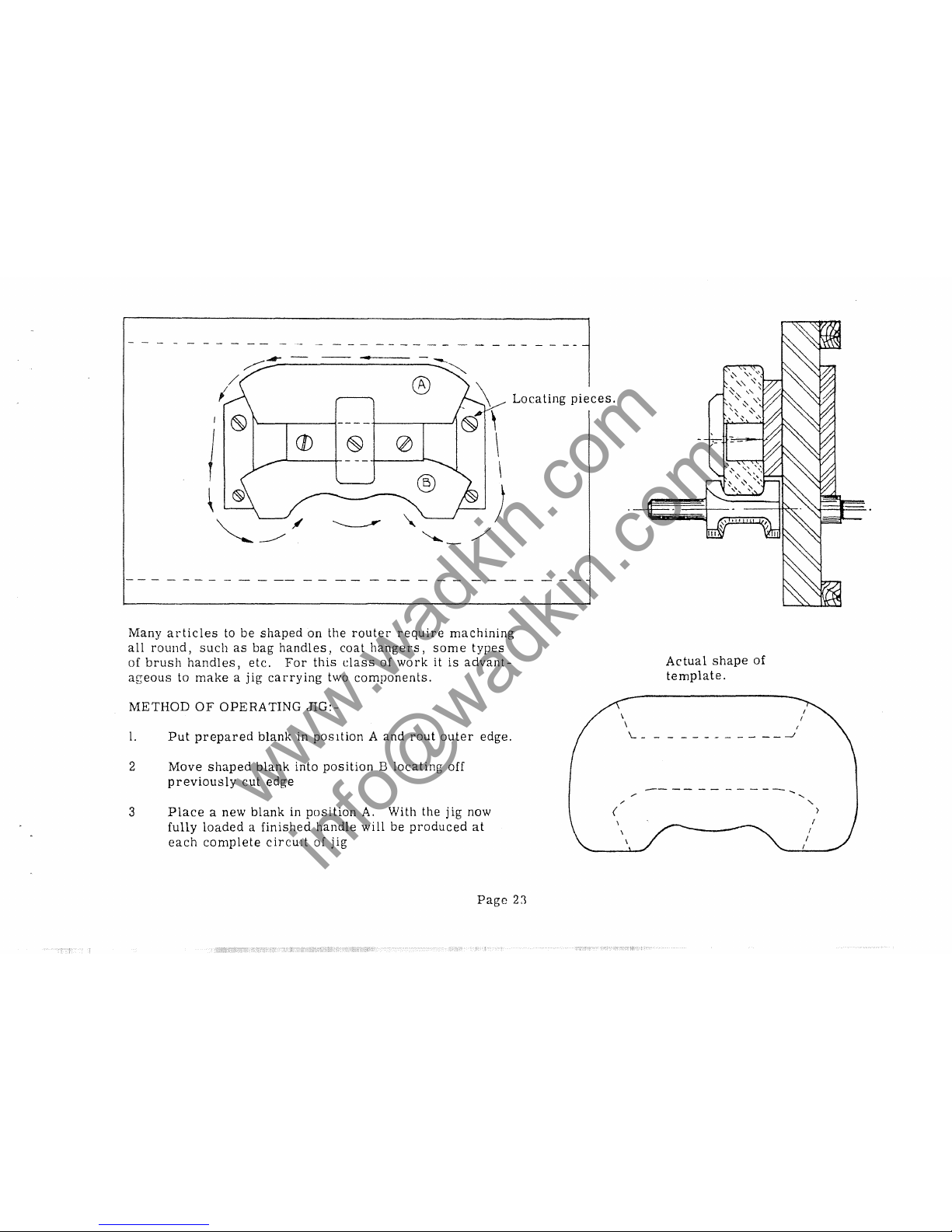
Locating
pieces.
Many
articles
to
be
shaped
on
the
router
require
machining
all
round,
such
as
bag
handles,
coat
hangers,
some
types
of
brush
handles,
etc.
For
this
class
of
work
it
is
advant-
ageous
to
make a jig
carrying
two
components.
METHOD
OF
OPERATING
JIG:-
1.
Put
prepared
blank
in
position A and
rout
outer
edge.
2
Move
shaped
blank
into
position B locating
off
previously
cut
edge
3
Place
a new
blank
in
position
A.
With the
jig
now
fully
loaded a finished
handle
will
be
produced
at
each
complete
circUlt
of
jig
Page
2:1
(
\
\
'--
/
Actual
shape
of
template.
_________
--.-1
I
"-
"-
)
www.wadkin.com
info@wadkin.com
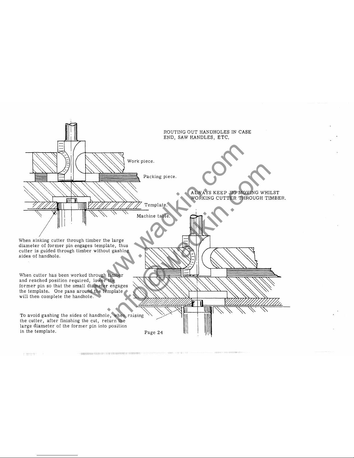
ROUTING
OUT
HANDHOLES
IN
CASE
END,
SAW
HANDLES,
ETC.
Packing
piece.
ALWAYS
KEEP
JIG
MOVING
WHILST
WORKING
CUTTER
THROUGH
TIMBER.
Template.
~~~~~~~~~~~
When
sinking
cutter
through
timber
the
large
diameter
of
former
pin
engages
template,
thus
cutter
is
guided
through
timber
without
gashing
sides
of
handhole.
When
cutter
has
been
worked
through
timber
and
reached
position
required,
lower
the
former
pin
so
that
the
small
diameter
engages
the
template.
One
pass
around
the
template
will then
complete
the handhole.
To
avoid
gashing
the
sides
of
handhole,
when
the
cutter,
after
finishing
the
cut,
return
the
large
diameter
of the
former
pin
into
position
in the
template.
Machine
table.
Page
24
www.wadkin.com
info@wadkin.com
L
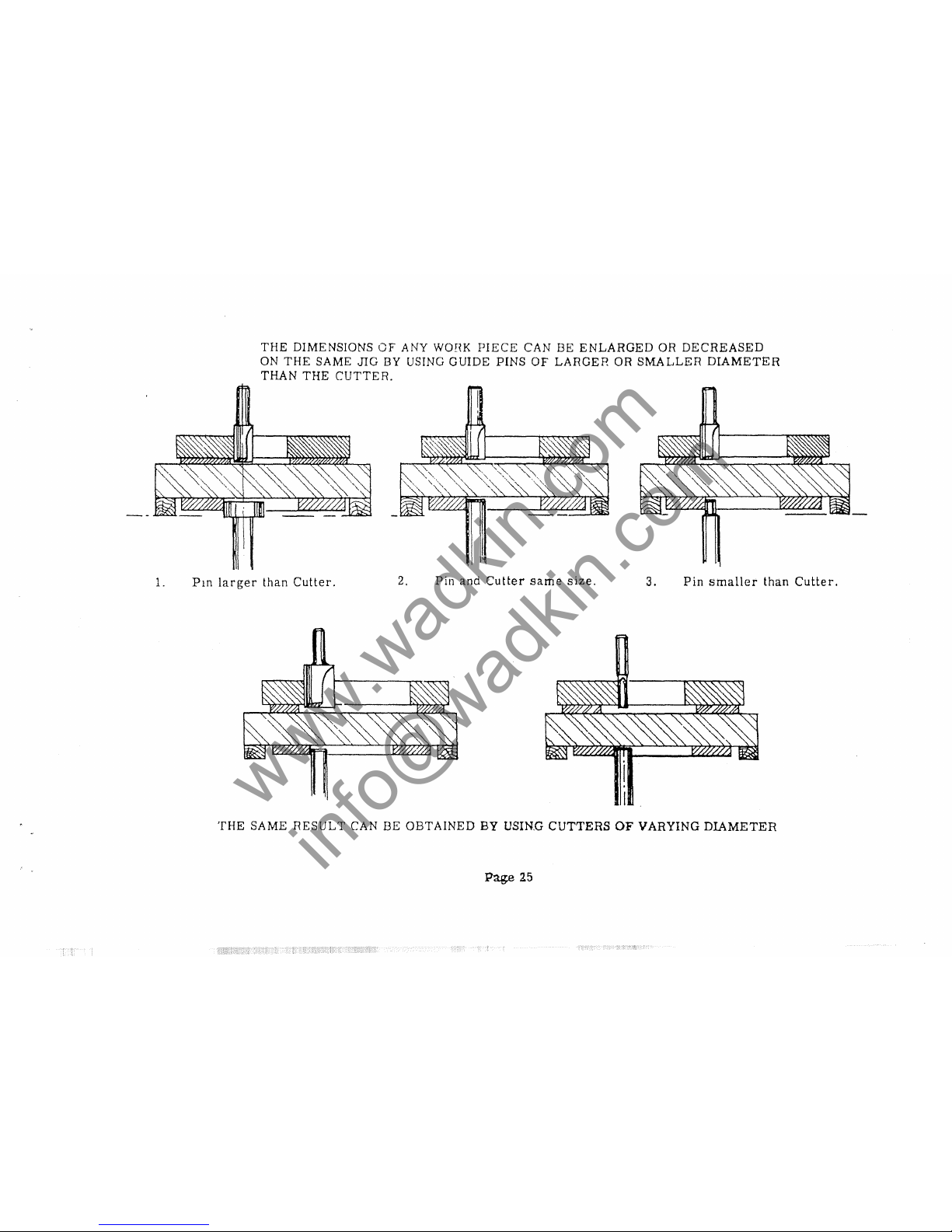
THE
DIMENSIONS
OF
ANY WOHK
PIECE
CAN
BE
ENLARGED
OR
DECREASED
ON
THE
SAME
JIG
BY USING
GUIDE
PINS
OF
LARGER
OR
SMALLER
DIAMETER
THAN
THE
CUTTER.
PlO
larger
than
Cutter.
2.
Pin and
Cutter
same
size.
3.
Pin
smaller
than
Cutter.
THE
SAME
RESULT
CAN
BE
OBTAINED
BY
USIN.G
CUTTERS
OF
VARYING
DIAMETER
Page
25
www.wadkin.com
info@wadkin.com

®
®
1
1 \
I I .
A.
Cutter
in top
position
and
former
pin
engaging
first
template.
D.
Head
lowered
to
serond
position
and
former
pin
raised.
C.
Head
lowered
to
bottom
position
and
former
pin
raised
to
engage
third
template.
Recesses
of
various
depths
such
as
those
in
Cutlery
trays,
Tap
and
Die
cases,
types
of
Brush
backs,
etc.,
can
be
worked
by
making a jig
with
multiple
templates.
Each
template
corresponding
to
the
recesses
of
one
depth.
Mount the
templates
in
one
pack
on
the
jig
body
and
raising
the
former
pin
by
the
hand
lever
on
the
front
of
the
machine
table -each
template
can
be
engaged
in
succession.
The
various
depths
of cut
are
pre-set
by
the
variable
stops
on the
router
head.
Page
26
www.wadkin.com
info@wadkin.com

-_._
..
Finished
article.
( )
(
)
( )
(
=
:)
First
template
itA
It
r--
- - - - - - -
--,
!
)
.........
- - - - - - - - - -
---"
( )
(
)
(
=
)
Second
template
"B"
Page
27
Section
across
tray.
First
depth.
Second
depth.
Third
depth
o
Details
of
templates
for
working
recesses
of
various
depths.
Third
template
'e
I
www.wadkin.com
info@wadkin.com

Track
of
cutter
1""--'
I
\
I
\
I
"-
/
\
I
" I
--"
Finished
component
spiked
to
locating
piece.
-
,
"-
\\
\\
-
"-
I
I
,/
Blank
Components
arranged
on
locating
pieces
around
jig.
'.
Templates
Plywood
surround
to
jig
body.
/
When
large
quantities
of any
small
artides
such
as
electric
light
ceiling
roseltes,
etc. , are
to
be
made,
it
is
often
advantageous
to
build a circular
jig
carrying a number
of
components.
By
using
this
type of
jig
the
operator's
position
in
relation
to the
machine
is
constant
and
excessive
move-
ments
of the
hands
avoided.
To
maintain
constant
production,
duplicate
jigs
can
be
used,
one
being
reloaded
whilst
operator
routs
with
second
jig.
This
eliminates
idle
machine
time.
Page
28
www.wadkin.com
info@wadkin.com

I
I
I
I
I
I
I I
, I
I'
I
I I
I :
Rauled
[ace
o[
wood.
Saw-rut.
Sm.l11
eirC'ubI'
'Jbjects
and
wheels
for
toys
can
be
made
by
sinking
cl
special
shaped
culler
inlo
the
surface
of
any
suitable
wood.
Saw
0[[
the
routed
[ace
lhen
the
wheels
will
fall
loose.
The
roulin€!
operation
can
then
be
repeated
on
the
stock
piece
of
wood
if
of
suitable
thickness.
Page
29
www.wadkin.com
info@wadkin.com

Standard
Cutterhead
LS.lb57H
Plywood
Machine
table
METHOD
OF
SCARFING
PLYWOOD,
ETC.,
ON A WADKIN
ROUTER.
Page
30
www.wadkin.com
info@wadkin.com

Two
strips
of
rubber
glued
to
face
of
jig
forming
both
vacuum
cavity
and
seal.
- - - - ---- -
~""iiiiiiiiiiiiiii
....
,
\
Taper
connection
with
valve
to
enable
suction
to
be
turned
on
and
off
at
will.
----------------------------~-
-----------
Hole
bored
in
end
of
jig
to
connect
with
hole
bored
from
face
of
jig,
JIG
BODY
Plastic
C'omponents,
draughtsmen
I s
protractors,
or
any I i[:';ht
article
reqUlrmg
routing
all
round
can
be
pI'oduced
by l1lukinp; a jIg
whereby
Lhe
components
are
held
by
suction.
Two
rubber
strips
are
glued
to
face
of
jig
confol'ming
to
Lhe
profile
of
the
component.
Place
the
blank
component
on
the
rubber
and
exhaust
Lhe
a
ir
from
between
the
strips.
Blank
will
now
be
held
firmly
during
routing.
Page
31
www.wadkin.com
info@wadkin.com

Type
of
jig
required
for
shaping
and
moulding
curved
chair
backs,
etc.
Shaped
table
cramped
to
router
table.
Cradle
to
carry
curved
chair
back.
Page
32
I I
I
'~
Former
pin
Front
of
router
table.
/'
/ )
/ I
/ /
/
,,/
/
www.wadkin.com
info@wadkin.com

i"'----
I
I
f~~
®
~
~
~;~
,
....-
......
I
@
$
\
~
I
'\
'-
\
eed
in
from
Front
of
router
table.
\
\
F
this
side.
Pressure
fence.
Position
of
cutter.
Simple
type
of
pressure
ience
to
enable
small
mouldings,
beads,
etc.,
and
lhicknessing
to
be
worked
on
Router.
Page
33
,..
\\
\
-
-
\
--
~
\
/
Fixed
fence.
Board
carrying
fences
clamped
to
router
table.
Front
of
machine,
www.wadkin.com
info@wadkin.com

,
,
)--
I
-,
--
-----1
,
,
Hardwood
'frame
around
composition
or
aluminium
jig
body.
)-
- - - - - - -
'-
- - - - - -
I
- - - - - - - - - - - - - - -
---"""
"
,
Light
alloy
component
supporting
posts.
Light
alloy
components
can
be
profiled
to
shape
by using a
jig
made on
principle
shown. The
supporting
posts
going
right
through
jig
body,
tracking
up both
template
and
component,
the
template
having
exactly
the
same
profile
and
tooling
holes
as
component.
Page
34
www.wadkin.com
info@wadkin.com

ECCENTRIC
CHUCKS
For
slotting,
small
morlices,
grooving,
etc.,
where
constant
cuttlDg
dIameter
is
important,
the
u~e
of
a.n
eccentric
chuck
is
advised.
The
cutters
are
only
sharpened
inside
the
flute.
Providl!1g
the
cutting
edge
is
always
set
in
position,
between
lhe
300 and
500 marks
as
shown
111
diagram,
the
effective
cutting
diameter
will
never
derrease.
It
is
important
that
the
right
combinations
of
cutter
and
chuck
as
set
out
on
the
chart
are
maintained.
If
nol,
cutter
burning
and
poor
work
will
result.
Eccentric
chucks
must
be
balanced
carefully.
SIZE
OF
DIAMETER
OF
CUTTER
EFFECTIVE
CUTTING
DIAMETERS
CHUCK
1/32
1
5/32 3/16
5/32
3/16
7/32
B
3/64
1
5/32 3/16 7/32 11/64 13/64
15/64 17/64
"8
1/16 3/16 7/32
1
5/16
1
9/32
5/H5
3
4"
4"
"8
3/32
1
5/16
:I
11/32
13/32 15/32
4"
"8
1
5/16
J
13/32 7/16
7/16
1
17/32
9/16
"8
"8
'2
5/32
J
13/32 7/16 15/16
17/32 9/16 19/32
5
"8
8"
DIMENSIONS
OF
CUTTERS
FOR
ECCENTRIC
CHUCKS.
-4£1
'
f'··
. . A
,
A
1..
..
5/32"
3/16"
7/32"
1..11
5/16"
1"
13/32
"
7/16"
15/32"
1.."
8
4
8
2
B
31/32"
31/32"
31/32"
31/32"
1.3/16"
1i"
It"
It"
It"
It"
It"
C
9/16"
9/16"
E.11
E.11
111
7/8"
1
k"
1
t"
1.
3/16"
1.
3/16"
It"
8 8
<I
Page
35
r11>
I
www.wadkin.com
info@wadkin.com

Eccentric
chuck.
-I-
Size
of
chuck
ViS
stamped
here.
_--Ml.LL.fo..l.li\ll'----.
ctt· 0
. 3p
To find the
cutting
diameter
of
any
respective
chuck
and
cutter,
add
the
chuck
size
tD
the
diameter
of the
cutter.
The
cutting
edge of the
cutter
must
be
either
on
or
between
the
lines
marked
300-50
0
to
ensure
cutter
clearance
and
the
best
cutting
angles.
With
cutter
so
set a chuck
marked
1/16"
and a cutter
t"
diameter
will
cut
5/16"
diameter.
Page
36
500 Line
300 Line
Correct
setting
of
cutter
in
chuck
500 Line
300 Line
Incorrect
500 Line
300 Line
Incorrect
www.wadkin.com
info@wadkin.com

It
is
importallt
that
an
eccentric
chuck
should
be
balanced
every
time
the
cutter
is
changed.
The
cutter
being
set
in
its
correct
cllLtin~
position
before
the
balance
operation
is
carried
out.
Dalallcil1[,("
plate
is
levelled
by
means
of
three
adjustable
sne'.vs.
Then
tile
ciluck
is
Inserted
in
the
balancing
roller
alld
tile
('orrect
balance
IS
obtained
by
inserting
or
withdraw-
in~
lJalaIlcil1~
screws.
When
the
chuck
is
perfectly
in
balance
the
roller
wi
II
come
to
rest
in
any
position.
The
pbte
can
be
levelled
by
testing
with
the
balancing
roller
only,
or
spirit
level.
Great
care
must
be
taken
with
the
11)11cr,
never
allowing
the
rims
to
be
bruised.
Page
37
www.wadkin.com
info@wadkin.com

Rebating
across
or
with the
grain.
3/16"
,.
taximum
depth
of
cut when
edging
shaped
work
rrr-r-r"',"-,-j--'>-lo~-rTl111
I
~
2".
For
this
class
of
routing
3/16"
is
the
. .
l'
maximum
amount
of wood
to
I
remove
continuously.
2"
50
m/m
\
EXAMPLES
OF
EXTREME
CUTS
POSSIBLE
ON
WADKIN
ROUTER.
t"
3
m/m
Maximum
dimension
of
moulding on
Router.
www.wadkin.com
info@wadkin.com

'.',
r
!
f,
··--F
, ,
~
'::~
,
--t
'-'\.
;'
-
~~
r'
..
,
t-
u
~'
~
n
~~>----:..~,
_
~
__
~L
19/16"1
:.-
--.,J
Ma.x:mum
sIzes
double
rebate
Maximum
size
of
groove
Smallest
broove
possible
EXAMPLES
OF
EXTREME
CUTS
POSSIBLE
ON
WADKIN
ROUTERS.
Maxi
mum
size
of
flute
Maximum
and
mmimum
sizes
of
dovetail
grooves
r
Maximum
and
minimum
sizes
of
nosin~
(rounding)
cutters
Type
23.
www.wadkin.com
info@wadkin.com

A
Spring
Pressure
Cramp
can
be
fitted
to
the
Router
Head to
ensure
that
hardwood
components
are
pressed
onto the jig.
Also
preventing
the
component
lifting
off the
spikes.
The
spring
pressure
helps
to
provide
accurate
routing.
Applicable
when
routing
thin plywood,
veneers,
plastics,
and
hardwood
components
which
are
held
to the
jig
by
spikes.
Page
40
)'fj'IiJ'1
Cramp
www.wadkin.com
info@wadkin.com

Double
Edged
Cutters -Panel
Type
4.
Relief
or
clearance
always
increasing
from
the
'\
cutting
edge
Face
Cutter
as
sent
out
by
Wadkin
Ltd.
Hump
behmd
cutting
edge.
Cutter
incorrectly
ground
and
honed.
'VCutting
edge.
Face
ground.
straight.
Single
Edge
Cutters-Spoon
Type
1.
Incorrect
grinding
will
result
in
cutter
breakage
and
bad
work.
Relief
restored.
Cutter
regl'ound
correctly.
Page
41
www.wadkin.com
info@wadkin.com

CUTTER
GRINDING
To
obtain
consistently
good
work
from
high
speed
routing
it
is
essential
that
the
cutters
are
kept
sharpened
and
ground
correctly.
This
can
only
be
assured
when
suitable
equipment
is
available.
The
ideal
grinder
for
this
purpose
is
the
Universal
Type
N.
H.
shown left. Not only
will
this
machine
deal
with
all
router
cutters,
but
it
is
indispensable
for
maintaining
every
type of
cutter
equipment
used
in a woodworking
plant,
excluding
long
planer
knives.
NOTE -
Where a suitable
grinder
is
already
installed
we
can
supply
the
set
of
fixtures
for
router
cutters
as
used
on
this
machine.
Where
the
amount
of
cutter
gylnding
does
not
justify a Un
iversal
Grinder
we
recommend
the
N.
U.
type
machine
'shown
right.
This
machine
has
been
specially
designed
for
router
cutters.
It
is
self-contained
and
provided
with a
precision
grinding
spindle.
Table
has
movement
in
three
directions
and
is
designed
to
take
fixtures
for
handling
all
types
of
rou
ter
cutters.
Whilst
we
strongly
recomm-
end
the
use
of a
separate
grinder,
where
the
number
of
cutters
to be
maintained
does
not
justify
either
of the
above
machines,
we
can
supply
the
fixture
shown
left
for
use
on the
Router
itself.
In
this
case
it
is
essential
to
use
the
Router
with
speed
18,000
r.
p.
m.,
this
lower
speed
being
necessary
for
the
grinding
wheels.
Page
42
www.wadkin.com
info@wadkin.com

INSTRUCTIONS
FOR
GRINDING
WADKIN
ROUTER
CUTTERS
A
sharp
and
properly
ground
cutter
is the key to good
routing.
It
is
important,
t.herefore,
that
the
operator
should
understand
exactly
what
he,
is
doing
when
sharpening
cutters.
Detailed
instructions
in the
grinding
of
all
types
of
router
cutters
are
given
on
the
following
pages,
and
if
read
carefully
and the
instructions
carried
out
will
ensure
trouble
free
running
and
high
production.
Page
43
www.wadkin.com
info@wadkin.com

WOODWORKING
CUTTERS.
CHOICE
OF
THE CORRE CT CUTTER.
In
order
to
get
the
best
results
from
routing
it
is
essential
to
use
the
proper
cutter
for
each
operation.
Straight
cutters
from
1/16"
diameter
to
1~"
diameter
are
available
in
varying
lengths.
A wide
range
of
shaped
cutters
can
be
supplied,
also
built-up
cutters
for
tonguing
and
grooving,
moulding,
etc. I circular
cutterblocks
and moulding
blocks.
Illustrations
show
some
of the
principal
types
in the
range.
TYPE
52
Panel
:Cutter
Head
TYPE
53.
Tonguing
and
Grooving
Arbor
"
,
TYPE 4
Double edge
Panel
Bit
TYPE
21
TYPE
1
Spoon
Bit
Solid
Profile
TYPE
55
Cutter
Circular
Block
When in doubt,
always
consult
Wadkin Ltd.
for
advice
and
recommendations.
More
information
on
cutter
types
can
bE;)
obtained
under
the following
References
:-
Cutters
for
Wood,
Plastics,
Synthetic Bonded
Ply.
Book No. 713
Router
operation,
Design
of Jigs'
and
Fixtures,
etc.
BookNo.716
THE AIM
OF
CUTTER SHARPENING.
The
primary
object
of
cutter
sharpening
is
to
restore
the cutting edge
at
the
correct
cutting
angle-,and
'ensure
correct
clearance
behind the cutting edge.
Relief
or
clearance.
Correctly
honed and
ground
cutter.
\, _ Face
not
straight.
Hump behind
cutting edge.
Incorrectly
honed
cutter,
Page
44
Worn
cutter
correctly
ground
and honed,
-~"»--
"j
-"
-Incorrectly
honed,
rubbing
on the
back.
.
Dotted
line
indicates
necessary
grinding
to
restore
cutting
edges.
www.wadkin.com
info@wadkin.com

THE
IMPORTANCE
OF
MACHINE
GRINDING.
The
key
to
high
quality
rouling
is
Cl
cutter
wilh clea:n
sharp
edges
and
smooth
continuous
relief.
In
order
to
maIntain
the
correct
cutting
angle
and
clearance,
machine
grinding
is
essential.
Experience
has
shown
that
free-hand
grinding
does
not
give
the
clean
smooth
edge
essential
for
good
cutting,
and
the
result
is
nothing
like
the life of a
machine
ground
cutter.
Another
import-
ant
point
is
that
it
is
almost
impossible
to
gr
ind
equal
amounts
from
both
edges
free-hand.
Mechanical
grinding
ensures
that
both
edges
of a
cutter
are
identical,
also
the
minimum
amount
of
metal
is
removed
at
each
regrind,
thus
making
sure
of
longer
life
from a cutter
than
when
most
carefully
free-hand
ground.
GRINDING
MACHINE,
TYPE
N.
U.
This
is
the
Grinding
Machine
generally
supplied
for
grinding
router
cutters
(see
illustration
on
Page
42).
It
has a spindle
speed
of
4,750
r.
p. m. and
is
prOVided
with
rise
and
fall,
and
also
traverse
movement
to the
table.
With the
aid
of the
three·
attachments
shown
overleaf,
most
types
of
cutters
for both
metal
and
wood
routing
can
be
dealt
with.
The
class
of
work
being
done
will
dIctate
the
attachments
needed,
but for wood
cutters
the
S.
F.
A.
attachment
is
essentlal,
and
the
P.
R.
F.
is
very
useful
for
regrinding
the
relief
on
straight
panel
cutters.
For
sheet
dural,
alclad
and
brass
the
D. G
A.
and
P.
R.
F.
attachments
are
essential.
Where
an
existing
Tool
Room
Grinder
of
suitable
type
and
having a speed
of
not
less
than
5000
r.
p.
m.
is
available,
the
grinding
attachments
only
are
needed.
In
such
cases
the
user
would
need
to
make a spindle
extension
arbor
to
suit
his
machine.
Page
45
www.wadkin.com
info@wadkin.com

GRINDING
ATTACHMENTS
ATTACHMENT
S.
F.A.
to
be
used
for
grinding
stra
ight
fluted
cutters
of
all
types,
also
ending
up
panel
cutters
and
Spoon
Bits.
This
attachment
will
generally
be
used
for
profiling
cutters
and
spoo"n
bits.
It
is
also
suitable
for
tungsten
carbide
cutters.
ATTACHMENT
D.G.A.
to
be
used
for
grinding
the
flutes
(spiral
or
straight)
of
all
alclad
or
dural
cutters
used
on
SHEET
WORK.
ATTACHMENT
P.
R.
F.
to
be
used
for
regrinding
the
eccentric
relief
on
panel
cutters;
suitable
for
dural,
alclad
and
brass
cutters,
after
loss
of
clearance
due
to
con-
tinuous
honing.
Page
46
Grinding
wheels
supplied
with
GRINDING
ATTACHMENTS.
FOR
ATTACHMENT
S.
F.
A.
ONLY
139
2"
diameter
~tI
FLAT
face
i"
Bore
2t"
diameter
1
It
CUP
i"
Bore
141
2t"
diameter
1"
DISH
f"
Bore
FOR
ATTACHMENT
D.
G.
A.
and
S. F.
A.
137
1jS
FOR
ATTACHMENT
S.F.A.
2"
diameter
137
3/16"
ROUND
edge
~
It
Bore
2
It
diameter
138 tit ROUND
edge
i
It
Bore
FOR
ATTACHMENT
P.
R.
F.
86R
Rougher
87 R
Finisher
146
These
wheels
are
used
for
grinding
chipped
ed~es
of
Tungsten
Carbide
Cutters.
Both
are
2t
lt
diameter,
1"
dish,
~"bore.
2t"
diameter
1
It
CUP
~"
Bore
www.wadkin.com
info@wadkin.com

LAPS FOR TUNGSTEN CARBIDE
TIPPED
ROUTER CUTTERS.
Diamond
lap
wheel
for
use
on
Attach-
ment
S.
F.
A.
and
used
for lap
finish-
ing
Tungsten
Carbide
Tipped
Cutters
after
regrinding
with
wheels
86R
and
87R.
145
.------:t:,==~
__
.,0<
__
~
..-.---
,...
s='--
~~
,"
Diamond
Impregnated
for
Hand Lap
honing
Tungsten
Carbide
Tipped
Cutters.
Also a similar
hone of
solid
material
in fine and
medium
grain
can
be
supplied.
Carborundum
Slip
Stones
for
High
Speed
Steel
Router
Cutters
No.183.
4%"
x 1;f"
xi"
-
3/16"
No.177.
4t"
x
n-!!
x
t"
-
1/16"
WHEEL
DRESSER DIAMOND',PART NO.
P.
R.
F.
37.
uRed
for
dressing
all
types
of
grinding
wheels,
excepting
the
Diamond
Lap Wheel,
No.145.
REGRINDING STRAIGHT
FLUTED
CUTTERS
OF
ALL
TYPES,
ON
ATTACHMENT
S.
F.
A.
LOC
U~JG
BOLT
FOR
CANTlNG
ARBOR
1.
MAX
BORE
Of
CHUCK
RADIAL
ADJUSTING SCREW
STOP
LEVER
FOR
INDEX
PLATE
-----(
COMBI~I[D
LOCKlt~G
BOLT
fOR
SWIVELLING
ARBOR
BRACKET
"ND
SECURING
BASE
TO
TABLE
ARBOR
HANDWHEEL
TYPES
OF
CUTTERS
MOST COMMONLY GROUND
ON
TIllS
ATTACHMENT
:-
--~
I
I
-
-1
Page
47
I
I
"
SPOON BITS.
Use
grinding
wheels
Nos. 137
and
138.
After
grinding
the
flute
I
it
will
be
necessary
to
stone a flat
on
the
cutting
edge
of
this
type
of
cutter
to
obtain
more
clearance.
The
out-
side
diameter
should
not
be
ground.
PANEL
ROUTER
CUTTERS
OR
SOLID
SHAPED
CUTTERS
Use
grinding
wheels
Nos.
140
and
141.
After
setting
up
as
described
opposite
both
flutes
should
be
ground
at
the
one
setting.
After
several
regrinds
of
the
flutes
it
becomes
necessary
on
this
type
of
cutter
to
give
more
clearance
on
the
back
of
the
cutting
edge
. (See
pages
48
and
49. )
www.wadkin.com
info@wadkin.com

TO
SET
UP FOR GRINDING
FLUTES.
First
bring
the
cutter
flute into
correct
relation
with
wheel.
Adjust
the
stap
on
machine
table
to
suit
length of flute
to
be
ground.
Use
table
move-
ment
to
grind
the
flute
taking
light
cuts.
To
put
on any
cut
use
the
radial
adjusting
screw,
thus
maintaining a correct
cutting
angle.
Both
flutes
should
be
ground
after
each
adjustment
to
ensure
that
each
is
ground
identically.
TO
SET
UP
FOR
GRINDING THE END OF THE
CUTTER.
First
turn
attachment
round
at
right
angles
to
grinding
wheel
and
lock
up.
Bring
cutter
into
correct
relation
with
wheel
and
adjust
stop.
Take
light
cuts
by
using
table
movement.
The
remaining
face
can
be
brought
into a
similar
position
by
using
Index
plate.
Use
grinding
wheels
140
and
141.
PERIPHERAL
RELIEVING
OR REGRINDIN G CLEARANCE
OF
PANEL
CUTTERS
ON .
ATTACHMENT
S.
F.
A.
The
best
results
on
relief
grinding
are
obtained
by
using
the
attachment
P.
R.
F.,
as
described
on
pages
49
to 53.
This
method
is
illustrated
for
operators
who
have
the S.
F.
A.
Attachment
only,
but
it
should
be
stressed
that
the
results
obtained
will
not
be
as
good
as
with
the
P.
R.
F.
Page
48
Fig.l
Shows a new
panel
cutter
with
plenty
of
clearance.
Fig.2
Shows the
same
cutter
after
several
regrinds
with
no
clearance.
www.wadkin.com
info@wadkin.com

PERIPHERAL
RELIEVING
ON
ATTACHMENT
S.
F.
A.
Cutter
is
moved
across
the wheel
by
table
move-
ment
as
for
grind-
ing the
flutes.
Take
light
cuts.
1st
stage
2nd
Stage
Fig.4.
Fig.
3
Use
wheel
No. 140
or
141
Using
same
wheel.
GRINDING
OF
SHAPED
CUTTERS
TYPE
NOS.
9, 11, 12, 32.
Shaped
cutters
must
only
be
ground
in the flute and
must
never
be
ground
on
the
straight
relief,
unless
the
shape
or
profile
of the
cutter
is
being
altered.
This
operation
is
done on the
S.
F.
A.
Attachment,
using
wheel
No. 141.
The
method
is
illustrated
right
and
described
on
page
48.
PERIPHERAL
RELIEVING
OF
PANEL
CUTTERS
ON
ATTACHMENT
P.
R.
F.,
ALSO SUITABLE
FOR
RELIEVING
OF
TWO-EDGED CUTTERS FOR SHEET DURAL, ALCLAD
AND
BRASS.
This
Attachment,
mounted
on
our
N.
U.
Grinder
has
been
designed
to
obviate
the
poor
results
obtained
when
operating
Routing
Machines
due
to
the
outside
relief
of
cutters
being
improperly
honed,
and
in
some
cases,
hand
ground.
It
consists
of a
base
plate,
on which is
pivoted a platen
carrying a swivelling
bracket,
on
which
in
turn
is
carried
the
spindle
head
which
can
also
swivel.
Both
the
swivelling
units
are
graduat
ed
and
the
control
knob
for
pivotrng
has
also a graduated
dial.
The
work
spindle
is
on the
eccentric
principle,
provision
being
made
to
vary
the
eccentricity
(or
radius
of
relief).
GRINDING
OF
GROOVING CUTTERS
TYPES
41
- 53.
These
cutters
must
never
be
ground
in
the
flutes
because
of the
loss
of width
which would quickly
result,
due
to
side
relief
of
cutting
edges.
Resharpen
these
cutters
by
grinding
on the
outside
face,
using
the
S.
F.
A.
Attachment.
Grinding
of
cutters
for
Flat
Knife
Chuck
No. 50,
Expanding
Cutter
head
No. 51,
Panel
Cutterhead
No. 52,
Circular
Block
No.
55.
For
resharpening
these
cutters
it
is
recommended
that
the
knives
be
removed
from
the
block
and
ground
freehand
on a
moulding
iron
grinder.
www.wadkin.com
info@wadkin.com

For
holding
the
cutters,
bushes
i"
and
i"
bore
are
provided;
these
have
two
lines
engraveq.
at
180
0
J
each
line
in
turn
being
brought
into
alignment
with a
zero
line
on the
spindle
nose
J thus
enabling
both
edges
of
the
cutter
to
be
ground
at
one
setting.
An
approximate
position
to
place
the
cutter
radially
is
also
indicated
by
another
line
on the
no
se
of
each
bush,
one
of the
cutter
edges
being
placed
opposite
this;
this
position
can only
be
approximate
as
some
cutters
require
more
drastic
relief
(or
clearance)
than
others.
This
variation
of
clearance
must
not
be
confused
with
varying
eccentricity
or
(radius
of
relief).
The
bushes
are
gripped
in a split
body
and
can be
changed
quickly.
A
holder
with
diamond
for
trueing
the
wheel
is
also
provided
and
fits
the
spindle
nose
the
same
as
the
cutter
bushes.
Arrangements
are
made
to hold the
work
spindle
radially
when
using
the
diamond.
Part
No. of
this
diamond
is
P.
R.
F.
37. .
It
is
absolutely
essential
to
true
the
grinding
wheel
with a
diamond. A special
fine
grain
wheel
No. 146
is
supplied
with
this
attachment.
TO
SET
UP FOR GRINDING.
First
set
both
swivelling
bracket
and
spindle
head
with
graduations
at
zero;
then,
with
thE}
vertical
movement
of
the
machine
table,
bring
the
attachment
spindle
to
the
same
height
approximately
as
the
grinding
wheel
spindle
(if
anything
the
centre
of
the
attachment
spindle
should
be a little
higher
than
the
centre
of
grinding
wheel
spindle).
Now
insert
cutter
with one
edge
opposite
the
line
on
the NOSE of
the
cutter
bush
and
tighten
firmly
with
the
set
screw;
then
set
cutter
bush
with
one
graduation
in
line
with
zero
line
on
spindle
nose
and
tighten
with
tee
headed
screw
shown in
right
hand
in
Fig.
2.
Fig. 3 shows
cutter
setting
line
on
nose
of
bush
and
also
one of the
bush
setting
lines
correctly
set
on the
zero
line
of
spindle
nose;
this
photograph
also
shows
the
actual
grinding
operation.
Fig.
2
Fig.
3
Page
50
www.wadkin.com
info@wadkin.com

It
will
not
be
necessary
as a general
rule
to
move
the
spindle
head
away
from
zero,
but
the
swivelling
bracket
(which
has
its
base
on the
platen)
will
require
moving a little
off
zero
for
the
spiral
fluted
cutters,
otherwise,
due to
the
spiral
angle,
the
grinding
operation
will
produce a taper
cutter.
For
right
hand
spiral
cutters
move
the
bracket
zero
line a little
to
the
left
and
vice
versa
for
left
hand
spiral
cutter.
Fig.4
shows
the
zero
line
on
bracket
moved
out
of
line
as
required
for a right
hand
spiral
cutter.
TO GRIND A
CUTTER.
Unscrew
control
1o1ob
shown
in
right
hand
on
Fig.
4 to
give
about
t"
opening
between
the
platen
and
base
plate.
Bring
the
table
up
until
the
surface
of
the
cutter
to
be
ground
is
1/16"
away
from
the
grinding
wheel;
then
move
table
stop
indicated
by
left
hand
up to
stop
bracket
and
tighten
tip.
Start
machine,
and
by
the
control
lever
rotate
one
edge
of the
cutter
to
and
fro,
bringing
the
cutter
into
contact
with
the
grinding
wheel
by
turning
the
control
knob
clockwise.
Take
care
not
to
take
the
control
lever
too
far
over
or
the
opposite
cutting
edge
will
come
into
contact
with
the
wheel
and
be
damaged.
Now
bring
the
table
and
fixture
away
from
the
wheel
and
note
the
number
of the
graduation
on the
control
knob
dial
which
is
opposite
the
zero
line
on the
platen.
Unscrew
control
knob
half
to
three
quarters
of a
turn,
unscrew
tee
headed
screw
shown
in
right
hand
on
Fig. 2 and
tUrn
cutter
holder
round
until
the
arrow
on
opposite
side
is
in
line
with
Zero
mark
on
spindle
nose;
left
hand
indicates
this
being
done (do not
release
cutter),
then
tighten
up
tee
headed
screw,
move
table
up
to
stop
and
proceed
as
before
until
dial
on
control
knob
comes
to the
same
number
as
before.
For
metal
routing
cutters
proceed
to
remove a fu
rther
.010",
to
cut
back
one
edge,
by
using
in
feed
of
machine
table.
See
Page
57.
"I
',',:1
'';.,
'~
'~
.
. . '
' . .J
Fig.
4
Fig.
5
Page
51
www.wadkin.com
info@wadkin.com

For
cutters
of
greater
length than the face of the
wheel,
repeat
the
operation
with
the
table
cross
traverse
adjusted
to
cover
the
remaining
length of the
cutter
edge. When
finishing,
pass
the
cutter
over
the
grinding
wheel
once
or
twice,
moving the
cross
traverse
slide
sufficiently
to
cover
the
whole length of the
cutting
edge
being
relieved.
On
short
cutters
move the
cross
traverse a little
each
way to
improve
the
surface
finish.
Fig. 5
shows
how the
eccentricity
(or
radius
of
relief)
is
varied.
The
spindle
nose
has
an
initial
amount
of
eccentricity
which
can
be
varied
as
follows
Ease
hexagon nut
indicated
by
right
hand, but
do
not
slacken
it
right
off;
slacken
off
the
small
screw
indicated
by
left
hand,
say a quarter
of a
turn,
and
tighten the one on the
opposite
side;
this
increases
the
eccentricity.
To
decrease
the
eccentricity
slacken
the
screw
on the
opposite
side
and
tighten
the
one
indicated
by
left
hand; then
re-tighten
the nut
indicated
by
right
hand.
On
no
account
try
to
adjust
without
easing
the
hexagon
nut and
be
sure
to
re-tighten.
The
amount
of
eccentricity
required
and
the
exact
position
to
·set
the
cutter
are
dependent
on
con-
ditions
and
must
be
left
to
the
operator
who
will
find
these
adjustments
quite
easy
after a little
experience.
Fig. 6 shows
the
split
chuck
and the
simplicity
of changing
cutter
bushes
or
inserting
the
diamond
holder.
All
that
is
necessary
is
to
release
the
tee
headed
screw
and
draw
the
bush
out;
insert
.,..-
..
~
..
another,
pushing
it
right
up to
the
shoulder;
bri
ng the
graduated
line
opposite
zero
line
on the
spindle
nose
and
re-tighten
the
tee
headed
screw.
See
that
bushes
and the
base
of
the
split
chuck
are
perfectly
clean
and
free
from
grit
.
Fig.
6
Page
52
www.wadkin.com
info@wadkin.com

TO DRESS THE WHEEL.
Fix
clip
onto
operating
handle
as
shown
by
right
hand in
Fig.
7, then
insert
the
diamond
holder
in the
spindle
nose
with
the
diamond
inclined
to
point a
little
below
centre
(this
is
important)
and
follow the
same
procedure
as
for
grind-
ing
cutters
(see
Page
51), using the
cross
slide
of
machine
to
pass
the
dia-
mond
across
the
periphery
of the wheel
and
the
control
knob
to
regulate
the cut
as
shown in
Fig.8.
Fig.
8
,
"."
~~~
'1'
....
•
Page
53
Fig.
7
See
that
the
table
stop
is
tight,
only
take
LIGHT
cuts
and
pass
the
diamond
over
the
wheel
slowly
and
with
a continuous
regular
motion. When mounting the
wheel
on
machine
spindle
place
it
with
the
recessed
side
towards
the
machine
as
shown in
Fig.2.
Frequent
dressing
of
the
grinding
wheel
is
not
necessary.
Considerable
quantities
of
cutters
should
be
ground
between
dress-
ings
and
after
the
initial
truing
of a new
wheel
subsequent
dressings
should
be
of
the
lightest
character.
www.wadkin.com
info@wadkin.com

Ragged
edge
after
grinding
I
Edge
after
Stoning
\
STONING
OF
CUTTERS
THE RIGHT AND WRONG WAY
OF
STONING
Shows
ragged
edge
of
cutter
after
grinding
the
flutes.
Shows
edge
of
cutter
after
Stoning.
Page
54
THE
RIGHT WAY -
Cutting
edge
is
on
the
outside
periphery
of
cutter
track,
with
back
of
cutter
clearing
the
job.
THE
WRONG
WA
Y -
Back
of
cutter
forms
outside
periphery
of
cutter
l
with
the
result
that
rubbing
of
the
back
on
the job
occurs.
- I
www.wadkin.com
info@wadkin.com

STONING
OF
CUTTERS
After
grinding,
the
cutter
must
be
stoned
up
before
using
to
remove
the
ragged
edge.
This
is
done by
using
a No. 183
or
177
Carborundum
slip
stone
dipped
in
paraffin
and
applied
td the
edge
of the
cutter
as
shown below. (Stones
are
illustrated
on
Page
47).
Correct
stoning
can
only
be
achieved
by
practice,
but
most
operators
have
no
difficulty
with
this
operation
after
a few
weeks
experience. A reliable
guide
as
to
whether
the
cutter
has
been
properly
stoned
will
be
that
the
job
will
almost
feed
itself,
instead
of
requiring
force
in
feeding
past
the
cutter.
In
addition
to
stoning
after
grinding,
the
cutter
will
need
restoning
between
regrinds.
The
length
of
time
the
cutter
will
retain
its
edge
will
depend on the
material,
and
may
vary
between
half
an
hour
and
. two
hours
or
more.
Here
again,
the
effort
required
to
feed
the
work
is
the
best
indication
of
the
condition
of
the
cutter
and
whether
stoning
is
required.
Stoning
for
half a minute
should
be
sufficient
and
the
cutter
should
stand
between
four
and
eight
restonings
between
regrinds,
depending
on the
skill
of the
operator.
Page
55
www.wadkin.com
info@wadkin.com

TYPICAL QUESTIONS
AND
ANSWERS
ON
WOOD
ROUTER CUTTER SHARPENING.
Is a c'utter
as
despatched
by the
makers
ready
for
use?
No.
It
requires
honing
or
stoning
before
being
used.
The
cutters
are
sent
out
as
they
leave
the
Grinding
Machine.
They
are
not
stoned
up
at
our
Works
as
the
edge
may
be
damaged
in
transit.
Is
the
use
of a slip
stone
necessary
on
router'
cutters?
Yes.
All
cutters
should
be
honed
before
using
on the
Router.
The
sharper
the
cutter
the
better
the
finish
and
the
faster
the feed.
What
sort
of
slip
stone
should
be
used,
and
what
methods
should
be
employed?
See
recommEnd
ations
as
regards
stones
011
Page
47,
and
the
method
of
stoning,
Pages
54-55.
How
often
should
the
cutter
be
honed?
This
depends
on the
timber
being
cut.
Stringy
timber
may
require a stone
on the
cutter
every
20
minutes,
while
on
clean
straight
grain
wood the
cutter
may
run
for
an
hour.
When
does
a cu
tter
need
sharpening?
When
the
work
is
difficult
to
push
past
the
cutter,
or
when
the
finish
is
not
clean
and
smooth,
the
two
characteristics
generally
go
together.
When the
cutter
is
sharp,
the
work
will
almost
feed
itself.
What
determines
whether a panel
cutter
should
be
ground
in the
flute
or
on
the
relief?
The
general
practice
is
to
grind
in
the
flute,
as
shown
on
Page
48,
and
continue
to do
so
until
the
relief
or
clearance,
shown
on
Page
44,
becomes
insufficient.
Then
regrind
Hie
relief
as
shown
on
Pages
49 to 52.
Is
there
any
means
of
truing
the
emery
wheels
on the
Cutter
Grinder?
Yes.
The
diamond
mounted
in a
steel
holder,
&"
diameter l is
shown
on
Page
47.
The
method
for
truing
wheel
No. 146
is
shown
on
Page
53. When
truing
the
face
of
the
wheel
No. 141,
mount
the
diamond
in
place
of the
cutter
on
the
attachment
S.
F.
A.
shown
centre
of
Page
48,
and
proceed
as
described
on
Page
53.
Is
machine
grinding
of
cutters
essential?
Yes.
To
get
good
work,
and
economy
of
cutter
tife.
See
Page
45.
Page
56
www.wadkin.com
info@wadkin.com

R
OUTER
CUTTERS
FOR
NON-FERROUS
METALS.
CUTTERS
FOR
NON-FERROUS
SHEETS,
Wadkin
cutters
are
made
in two
ranges,
one
having a profile
suitable
for
cutting
Dural
and
Brass,
and
the
other
suitable
for
cutting
Aluminium
and
Alclad.
In
general,
these
cutters
are
quite
suitable
for
use
as
sent
out,
without
modification
of the
profile,
but
some
operators
claim
to
obtain
improved
performance
by
sl1ghtly
modifying
the
profile
of the
cutter
to
suit
the
particular
specification
of
metal
which
they
are
cutt-
ing.
These
modifications
may
be
regarded
as
refinements
and
should
not
be
attempted
until
the
operator
has
become
quite
proficient
in the
use
of the
machine.
The
types
of
cutters
available
are
shown
on a
list
which is
issued
and
revised
from
time
to
time,
and
can
be
obtained
on
enquiry
from
us.
All Wadkin
cutters
are
numbered
and
it
is
advisable
to
quote
the
refer-
ence
number
when
ordering
or
referring
to
specific
types
and
sizes
of
cutters.
For
cutting
out
from
sheet
the
best
size
to
use
is
a~"
diameter
double-edged
cutter,
having
a
~"
diameter
shank.
It
is
possible
to
use
a
i"
cutter
where
i"
Internal
radii
are
essential
or
~"
diameter,
if
required.
L b
V?
~
n
Typical
cutter
for
profiling.
CUTTERS
FOR
PROFILING
CASTINGS
STAMPINGS
AND
NON-FERROUS
METAL
FACED
PLYWOOD,
ETC.
For
this
class
of
work
we
recommend
an
entirely
different
range
of
cutters
from
those
used
for
sheet
cutting.
In
general,
these
cutters
are Z section
with
straight
flutes,
but
it
is
advisable
to
consult
us
before
ordering
cutters,
to
ensure
that
the
most
suitable
type
is
used
for
the
particular
metal
to be cut
and
for
the
amount
of
metal
to
be
removed.
SIZES
OF
CUTTER
SHANKS.
All
cutter
shanks
on the
cutters
we
supply
are
held
to a limit
of
+.0005
and
-.0005",
i.
e.
a
tolera'nce
of one
thousandth
of
an
inch,
but
whatever
the
diameter
it
is
most
important
that
the
shank
is
parallel. A cutter
shank
over.
0005"
taper
will
not
give
satisfactory
results.
SMALL
CUTTERS
FOR
SPECIAL
WORK SUCH AS
GROOVING.
iVhen
using
small
cutters,
such
as
i"
or
3/16"
diameter,
we
recoglmend
ordinary
wood
cutting
spoon
bits,
and
these
are
quite
satisfactory.
Always
shorten
the
cutting
blade
as
much
as
possible
to
avoid
brealmge.
This
is
best
done
by
the
user
himself
as
the
cutters
can
then
be
shortened
to
suit
his
own type of
work.
Page
57
www.wadkin.com
info@wadkin.com

HOW
TO
TELL
WHEN A METAL
WORKING
CUTTER
NEEDS
RE-GRINDING.
The
first
thing a
rruting
machine
operator
should
know
is
how to
tell
when the
cutter
is
sharp
and
working
correctly.
The
answer
is
that
when the
cutter
is
right,
the
chips
will
leave
the
cutter
bright
and
curly,
and
the
feed
will
be
so
easy
that
the job
almost
feeds
itself.
When
these
conditions
exist
the
cutter
will
have
a long
life
between
grinds.
If
the
cutter
is
incorrect
ly
ground,
the
chips
will
come
off in
straight
shreds,
and
an
excessive
amount
of
force
will
be
needed
to
push
the job
past
the
cutter.
Good
work
is
out of
the
question
under
such
conditions,
and
there
is
always
the
danger
of
pushing
the end off the
cutter.
If
the
cutter
is not
working
correctly,
stop
the
machine
immediately
and
find
out
why.
To
ensure
the
maximum
life
of the
cutter,
and
at
the
same
time
obtain
free
cutting,
it
is
essential
that
the
cutter
is
kept
efficiently
lubricated.
Always
use a lubricant
consisting
of a
mixture
of
paraffin
and
lard
oil.
The
simplest
method
of
application
is by
brushing
the
lubricant
on to
each
blank
before
clamping.
The
lubricant
need
only
be
applied
on the
sheets
in the
track
of
the
cutter.
THE
IMPORTANCE
OF
MACHINE
GRINDING.
Wadkin
metal
working
router
cutters
(except
special
purpose
cutters)
are
supplied
with two
spiral
cutting
edges,
as
shown
in the
sketch
below.
Cutting
Edge
Cj
!j-~
7\fJ
Cutting
Edge
All
metal
cutting
router
cutters
have
one
edge
ground
back
.010.
This
is
done in the
formed
relief
grinding
so
that
the
normal
re-grl.nding
in the
flutes
of
the
cutter
will
not
be
affected.
In
order
to
preserve
the
cutting
diameter
resharpening
is
done by
regrinding
the two
spiral
flutes
equally.
Expe
rience
has
shown
that
free
hand
grinding
does
not
give
the
clean
smooth
throat
essential
for
chip
clearance
and
good
cutting
and,
in
consequence,
gives
nothing
like
the
life
between
grinds
that a machine-ground
cutter
gives.
Another
important
point
is
that
it
is
almost
impossible
to
grind
equal
amounts
from
both
edges
free
hand.
By
resharpening
by
mechanical
means,
not
only
is
accurate
grinding
ensured,
with
both
edges
of
the
cutter
ground
iden-
tically,
but
the
minimum
amount
is
removed
from
the
cutter
at
each
regrind,
ensuring a longer
life
than
1S
Possible
by
the
most
careful
free
hand
grinding.
For
details
of the
recommended
grinding
machine
and
attachments,
see
pages
42,
45
and
46.
Page
58
_
.i
www.wadkin.com
info@wadkin.com

REGRINDING
STRAIGHT
OR
SPIRAL
FLUTED
CUTTERS
FOR
NON-FERROUS
METAL
SHEETWORK
ON
ATTACHMENT
D.
G.
A.
/'
/D'
TO
SET
UP
FOR
GRINDING
STRAIGHT
FLUTES.
The
cutter
is
placed
in
the
spindle
nose
and
the
attachment
adjusted
to
bring
the
flute
into
correct
relation
with
the
wheel, i e. , parallel
with
the
table
slots.
The
table
and
cross
slide
should
then
be
locked,
and
the
rise
and
fall
of
the
table
o:rrJ.
the
radial
adjustment
screw
"A"
only,
should
be
used
during
the
subsequent
grinding
operation.
The
cross
slide
of
the
table
must
not
be
used
to
put
on
cut
after
once
setting
Use
grinding
wheels
up,
as
this
will
alter
the
r.ontour
of
the
flute,
thus
varying
the
cutting
angle.
Nos.
137
or
138.
TO
SET
UP
FOR
GRINDING
SPIRAL
FLUTES
ON
METAL
CUTTERS,
The
set
up
and
method
of
grinding
in
this
case
is
identical
with
that
for
the
straight
fluted
cutters
except
that
it
is
necessary
to
set
over
the
head
as
shown
below
to
bring
the
flute
into
the
correC't
parallel
relation
with
the
table
slots.
It
will
also
be
necessary
to
change
the
slotted
sleeve.
To
do
this
first
remove
the handwf-leel B
and
co
llar
C by
loosening
grub
screws
with
the
special
key
provided.
Sla·:ken
off
grub
screw
D
in
the
end
of
the
spindle
and
withdraw
guide
pin
E.
Unscrew
the
three
countersunk
screws F from
the
sleeve.
The
sleeve
is
now
free
to
be
with-
drawn
from
the
spindle.
Page
59
PLAN
VIEW
SHOWING
HEAD
SET
OVER
FOR
GRINDING
SPIRAL
FLUTES.
www.wadkin.com
info@wadkin.com

METHOD
OF
GRINDING
FLUTES
ON THE
ATTACHMENT
D.
G/A.
1
Bring
the
cutter
into the
correct
relation
with the
grinding
wheel
by
adjusting
the
table
slides.
Lock
table
slides
and
lock
cutter
as
shown above.
3
The
cutting
edge of the
cutter
is
adjusted
relative
to
the
grinding
wheel
by
turning
the
small
screw
as
shown above. Both
flutes
s.hould
be
ground
at
the one
setting.
If
after
examination
both
edges
have not
been
cleaned
up,
put
on
more
radial
cut
and
repeat
the
grinding
operation.
Both
flutes
should
be
ground
after
each
adjust-
ment
to
ensure
that
both
flutes
are
ground
2
The
grinding
is
done
bY
sliding
the
cutter
past
the
wheel,
taking
care
to
set
the
stop
collar
near
the
operating
handle.
This
motion
is
controlled
by a grooved
sleeve.
Raise
the
table
until the wheel
makes
contact,
and
draw
spindle
right
back
after
making
each
stroke.
Turn
through '180
0
•
then
grind
the
other
flute.
4·
After
grinding
one flute of
the
cutter,
the
spindle
is
drawn
back
to
bring
the
diagonal
pin
clear
of
the
bush,
as
shown below..
It
is
then
rotated
half a turn
to
bring
the
opposite
flute into
position,
when the
pin
can
be
re-inserted
in the bush.
identically.
Page
60
www.wadkin.com
info@wadkin.com

TYPICAL
QUESTIONS
AND ANSWERS ON
METAL
CUTTER
SHARPENING.
Is a cutter
received
from
the
Stores
re?dy
for
use?
No.
It
requires
honing
or
stoning
before
use.
The
cutters
are
sent
out
as
they
leave
the
Grind-
ing
Machine.
They
are
not
stoned
up
at
Qur
Works,
as
the
cutting
edges
would be
damaged
in
transit.
Is
it
permissible
to
use
an
oil
stone
on the
outside
of the
cutters
when dull ?
This
is
the
essence
of
routing
and the key
to
high
performance.
As soon
as
the
cutter
begins
to
drag,
stop
the
machine
and hone
up
the
cutter
on the
outer
edges
until they
are
sharp.
This
can
easily
be done in
half
a minute and the
method
is
iilustrated
on
pages
54
and
55.
How
often
should a metal
working
cutter
be
stoned?
About
every
hour.
On
hard
material
it
may
be
every
half
hour.
On
some
soft
materials
every
two
hours,
but
on
aluminium
and
alclad
sheets
it
pays
to
keep the
cutter
sharp
to
prevent
pack-
ing on the
cutter.
How
many
times
should a cutter
be
stoned
between
regrinds?
A
cutter
should
stand
four
to
eight
stonings
depending on the
skill
of the
operator.
What
stone
should
be
used
and
should
it
be
used
dry?
A No. 183
Carborundum
Slip Stone. Dip the
stone
in
oil
and
paraffin
to give the
best
results.
Should the
cutters
be
used
dry
on
metal?
No. Always
use a lubricant
consisting
of
paraffin
and
lard
oil,
mixed
and
applied
to the
sheets
by
brush
before
commencing
to
cut. The
paraffin
is
only a
thinner
to
help
to
spread
the
lard
,
oil,
and
only enough for the
purpose
should be
used.
Excessive
paraffin
causes
a blue
smoke
when cutting.
What
causes
metal
chips
to
pack on the
cutter?
Generally,
blunt
cutters.
The
wrong
shape
of
cutter,
especially
on
aluminium
and
alclad
sheets
will
cause
it,
also a lack
of
lubricant.
What
causes
chips
to {Jack in the guide
h\lsh?
Blunt
cutters.
They
make
shreds
of
swarf
which
work
up into the
bush
and
weld
to
the
shank.
If
the
cutter
is
correct
the
large
curly
chips cannot
possibly
get
into the
small
clearance
between
cutter
and guide bush.
What
causes
shudder
when
cutting?
The
cutter
has
not
been
stoned.
The
rough saw edge
left
by
the
grinding
wheel
causes
it.
To
cure
it
s tone the
cutter.
Page
61
www.wadkin.com
info@wadkin.com

TYPICAL
QUESTIONS ANO ANSWERS -
Continued.
Can
the
loss
of
diameter
due
to
cutter
wear
be
compensated
for?
Yes.
All
Fixed
Head
Routing
Machines
are
now
sent
out
with a
range
of
graded
pins
.005",
. 010", . 015", . 020" on
all
sizes.
On
the
Radial
Machine,
undersized
guide
bushes
can
be
supplied.
What
is
the
feed
speed
on the
Router?
Feed
as
fast
as
the
cuttH
will
take
it.
If
the
cutter
is
sharp
the job
will
almost
feed
itself
and
will
only
require
guiding.
If
the job
needs
pushing
the
cutter
is
not
sharp.
On
metal,
a good
speed
on
straight
work
is 4 inches
per
second.
On
intricate
shapes,
it
is
impossible
to
feed
at
this
speed,
and
the
limitation
is
the
speed
at
which
the
operator
can
manipulate
the
job,
generally,
1 to 2
inches
per
second.
Can
sheet
steel
be
routed?
No,
only
non-ferrous
metals
such
as
Alclad,
Dural,
Aluminium,
Brass,
Copper,
Lead.
Not
Bronzes,
2incs
or
Tin.
TUNGSTEN CARBIDE
TIPPED
ROUTER
CUTTERS.
As a
general
rule,
tungsten
carbide
cutters
should
only
be
used
when high
speed
steel
cutters
will
not
stand
up to
the
hardness
of
the
material
being
routed.
They
are
not
suitable
for
ordinary
timbers
and
will not
cut
half
as
cleanly
as
high
speed
steel
on
wood.
Tungsten
carbide
cutters
are
necessary
on
the
following
materials
:-
Resin
bonded
plywoods,
wood
pulped
board
and
wall
board,
plastics
such
as
Holloplast
and
Catalin.
Linen
and
paper
based
materials,
such
as
Tufnol
and
Elephantide.
Aluminium
alloys,
die
cast
or
wrought,
containing
silicon
or
manganese
(there
are
certain
high
silicon
alloys
which
are
too
hard
even
for
tungsten
carbide
on
the
router).
All
sand
cast
aluminium
castings.
Type
60, Two
Edged
Panel
Cutter,
for
cutting
outside
profiles
only.
Not
suitable
for
sinking
or
cutting
inside
profiles.
Dia.
i"
tIt
t"
Length
on
cut
3"
3"
1+"
4"
:r
~
Type
61, Two
edged
Panel
and
cutting
on
side.
Dia.
i"
t"
Cutter,
for
sinking
. + .
=tiid-.
Length
t~~
cu t 1 "
Type
62,
Single
Edge
Spoon
Bit,
suitabl e for
sinking
and
cutting
on
side.
+-
Diameter
i"
~-
Length
on
cut
i"
Page
62
Other
sizes
and
profile
cutters
of
all
types
are
available
to
special
order.
www.wadkin.com
info@wadkin.com

r
SHARPENING
TUNGSTEN
CARBIDE
ROUTER
CUTTERS.
Tungsten
carbide
cutters
cannot
be
sharpened
with
ordinary
grinding
wheels
or
honed
with
Carborundum
honing
stones.
The
grinding-
can
be
done
on
the
N. U.
Grinder
and
S.
F.
A.
Attach-
ment
described
on
pages
45
-46,
using
grinding
wheels
86R
and
87R
describe~
on
page
46.
Use
the
wheels
dry;
86R
for
roughing,
taking
very
light
(uts,
and
expect
to
take a long
time
remov-
ing a small
amount
of
carbide.
Finish
grind
dry,
using
wheel
87R.
In
order
to
get a good
cutting
edge
it
is
necessary
to
machine
lap
with
wheel
No.
145.
This
wheel
is
made
from
soft
material
and
its
cutting
edge
is
impregnated
with
diamond
dust
It
is
expensive
to
use
and
should
be
used
for
final
finishing.
It
('an,
of
course,
be
used
for
grinding
in
place
of
the
f.6R
and
87R
wheels,
but
the
wear
and
cost
of
the
laps
would
be
prohibitive.
Never
attempt
to
true
the
diamond
lap.
When
using
the
machine
lap
smear
the
face
of
the
wheel
with
oil
and
then
take
the
lightest
possible
cuts
to
get a polished
face
and a clean
edge.
Finish
the
cutting-
edge
with a hand
lap,
which
is
also
impregnated
with
diamond
dust
and
is
illustrated
on
page
47.
The
best
method
of
using
the
hand
lap
is
to
immerse
the
lap
and
tool
under
water
and
hone
in
this
position.
This
is
recommended
so
that
the
diamond
dust
freed
from
the
lap
floats
to
the
surface
of
the
water
and
does
not
be('ome
abrasive
between
the
cutter
and
the
lap,
causing
excessive
wear
on
the
lap.
If
this
is
not
possible,
use
as
much
water
as
possible
to
swill
off
the
diamond
dust.
The
general
instructions
on
stoning
cutters
on
pages
54-55
apply
to
tungsten
carbide
cutters
except
that
the
diamond
lap
is
used
instead
of
the
Carborundum
stone.
Tungsten
carbide
cutters
sent
out
from
our
Works
require
honing
with
the
hand
lap.
Page
63
www.wadkin.com
info@wadkin.com

CONCERNING
CUTTER
COLLETS.
Never
over-tighten a collet.
The
short
spanner
or
screw
key
provided
is
designed
to
give the
maximum
grip,
when
used
by the
average
operator.
The
use
of a
pipe
wrench
strains
the
collet
and
actually
reduces
the
grip
on the
cutter.
Never
allow
cutters
to
project
from
the
collet
more
than
is
absolutely
necessary.
It
is
a golden
rule
that
the
nearer
the
cutter
to
the
collet,
the
better
the cut and the
longer
the life of the
cutter.
Page
64
- I
www.wadkin.com
info@wadkin.com

{
WIRING
DIAGRAM,
ROUTER
MODEL
L.S.
D.
1026/1.
'.:oE.I..E.CTOFl.
~WITCH
CO~"'E.CT'O""'::l
(I) '\..ow'
CONN
E.C
T~
I
TO
Z.
5 TO 6
(r:!)'HIC.H'CON~E..C.i~
3
T04-
7
TO
1:1
~UPP\"Y
~TATOR
d,-------
-~
A
e.
Cl,
I
1
I,
I
I , I I
I~LlP
I I I I I
1l"-IN"~
t I At.
~
ZJ
0
t.
,.
I I I
...1
______
...1-
J-----L/
ORIYE.
'r
- -
....
>10"0/
--1--"_'
____
...
F"Fl.!:.Q.!:.!'I.C'( CHAI'<C,t.R
~E.T,
Page
65
INSTALLATION INSTRUCTIONS
Fit
isolating
switch
near
machine
so
thal
the
electrical
gear
may
readily
be
isolated
for
inspection
purposes.
Bring
supply
cables
to
isolating
switch
and to
LI-L2-L3
at
contactor
through
conduit
which
should
be
screwed
into the
control
gear
box and
secured
by
means
of
locknuts.
Remake
the following
connections
which
are
broken
for
transit,
at
terminal
blocks
in
control
gear
box:-
drive
motor
at
terminals
AI-
B1-C1,
slip
rings
at
terminals
A-B-C,
connect
router
head to
frequency
changer
terminals
D-E-F.
Ensure
that
the
direction
of
rotation
is
correct
before
putting
the
machine
into
service.
to
reverse
rotation
interchange
L1
and L3
at
contactor.
OPERATING INSTRUCTIONS
To
start
machine:
close
isolating
switch
and
press
"start"
button. To
stop
machine:
press
"stopll button. To lock off
machine:
press
and
turn
n!:itop" button,
this
must
be
released
before a start
can
be
made.
OVERLOAD
Should
the
machine
stop
due to
overload
wait
for a short
time
to allow
coils
to
cool, then
start
in the
usual
manner.
The
overloads
are
set
at
these
works
at
"auto"
for
automatic
reset
after
tripping,
if
set
at
tlhand" the
plunger
on
the
overload
assembly
should
be
depressed
to
reset.
www.wadkin.com
info@wadkin.com

·
..
blow away harmful dust,
chips
and
dirt
with
a
Blower
Wadkin
Electric
No
motor
can
run at its maximum efficiency with its ventilating
duct
or
control gear covered with dust and dirt. Sooner
or
later
the
resultant overheating will cause serious trouble.
Similarly. accumulations of chips and dust.
in
the mechanical parts of
the
machine
can
interfere with its efficiency. A few minutes a week
for blowing down
all
Woodworking
Machinery will
be
amply repaid
in
better
and easier running.
in
increased life. and freedom from
breakdown.
Blowers can be supplied for single phase A.C.
or
Direct
Current
for any voltage up to 250.
Please
state
voltage when
ordering.
www.wadkin.com
info@wadkin.com

SPARE PARTS BOOKLET
CONTENTS
1.
Basic
ordering
requirements.
2.
Sample
type
order
•
.
3.
List
of
item
numbers
and
description
of
item.
4.
Drawing
showing
item
numbers.
LSA
HIGH
SPEED
ROUTER
COMPOUND
TABLE
"
WADKIN
LTD.
G R E E N
LA
N E
WO
R K
S,
L E
ICE
S T
ER,
E N G L
AND.
www.wadkin.com
info@wadkin.com

SPARE
PARTS
ShouLd
spare
parts
be
required
due
to
breakage
or
wear
full
particulars
including
the
machine
'and
test
number
must
be
given.
This
information
is
on
the
nameplate
attached
to
the
machine
and
will
be
similar
to
the
picture
below.
o
~J.3:*_~
hlhCHINb TSST
NO.
1
70601
I
pA.TE:NT
NO.
I
'~
VO!ti'AG~
CYCLZ3
I
50
3';;;:;
~lAINi.'<:;l.;UIC:5:
INSTrlUCTIJ('
o
E:)O:~
Fort
LJB,{IC..I.TIO:; DE'l'AIL9
(0
Please
see
the
next
page
for
sample
detail
of
how
to
order
spare
parts.
www.wadkin.com
info@wadkin.com

SAMPLE
TYPE
ORDER
MACHINE:
LSA
ROUTER
MACIDNE NO:
1407
TEST
NO:
68975
PARTS REQUIRED
1
LSI077/LSl1
Head
Link
1
LS1077/LSl8
Locking
Ratchet
Bracket
1
LS1077/LS74/B
Lower
Lever
1
LS1077/LS468
Release
Pedal
Lever
1 -
LS1077/LS649
Foot
Pedal
www.wadkin.com
info@wadkin.com

ITEM
NUMBER
LSl077/LQ5l
LSl077/LQ52
LSl077/LQ53/A
LSl077/LQ54
LSl077
/LQ55
LSl 077 /LQ57
LSI077/LQ58/A
LSl 077
/LQ59
LSl
077 /LQ82
LSl077/LQ83
LSl077/LQ84
LSl077/LQ85
LSl077/LQ86
LSl077/LQ87
LSl077/LQ88
LSl077
/LQ89
LSl077/LQ90
LSl077
/LQ9l
LSl 077 /LQ94
LSl
077
/LQl5l
LSl 077 /LQ152
LS1077/LQ153
LSl077/LQ154
LSl077/LQl55
LSl077/LQ156
LS1077/LR32
LS1077/LRl51
LSl077/LR155
LSl 077 /LR156
LS1077
/LRl57
LS
SPARE
PARTS
LIST
DESCRIPTION
INTERMEDIATE
SLIDE
TABLE
SLIDE
VERTICAL
SLIDE
PWNGER
KNOB
BEARING
FOR
TABLE
SCREW
PLUNGER
BRACKET
PLUNGER
LEVER
STOP
BAR
FOR
BOTTOM
SLIDE
TABLE
STOP
LOCKING
BOLT
FOR
STOP
STOP
PLUNGER
STOP
COVER
PLATE
FOR
PLUNGER
BOTTOM
PLATE
FOR
PLUNGER
BUSH
FOR
PLUNGER
PINION
FOR
PLUNGER
PLUNGER
LOCATING
PIN
FOR
PLUNGER
SPRING
FOR
PLUNGER
SHAFT
FOR
RAISING
MI
TRE
FEED
SCREW
WORMS
HA
FT
RACK
FOR
TABLE
SPIGOT
FOR
SLIDE
CLAMP
PLATE
NUT
FOR
TABLE
SCREW
WORM
FOR
TABLE
RACK
SLIDE STRI P
BACK
L/H
SLIDE STRIP
FRONT
L/H
SLIDE STRI P R/H
www.wadkin.com
info@wadkin.com

LSI077/LR158
LSI077
/LR162
LSI077/LR163
LSl
077
/LRl64
LSI077/LR165
LSI077/LR166
LSI077/LSl/C
LSI077/LS7
LSI077/LS8
LSI077/LS9
LSI077/LSll
LSI077/LS18
LSI077/LS74B
LSI077/LSI03
LSl
077
/LSI04
LSI077
/LSI05
LSl
07 7 /LSl
06
LSI077/LSI07
LSI077
/LS1l7
LSl
077
/LSl18
LSI077/LS119
LSI077/LS120
LSI077
/LS121
LSI077/LS123
LSI077/LS125
LSI077
/LS126
LSI077/LS128
LSI077
/LS131
LSI077/LS138A
LSI077
/LS139
LSI077
/LS168
LSI077/LS169
WEAR
SlRIP
TABLE LOCKING
ROD
TABLE
LOCKING
PAD
SLIDE
LOCKING
ROD
SLIDE LOCKING
CAM
SLIDE
LOCKING
PAD
MAIN
FRAME
DEPTH STOP BASE
DEPTH STOP
QUADRANT
NUT
FOR
RAISING
SCREW
HEAD
LINK
LOCKING RATCHET
BRACKET
LCMER
LEVER
TABLE
STOP
WIDE
STRIP
FOR
SLIDE
NARROW
STRIP
FCR
SLIDE
WEAR
STRIP
FOR
SLIDE
LOCKING
COLLAR
FOR
TABLE
FULCRUM
SHAFT
FOR
LO'iER LEVER
WASHER
FOR
La'lER
FULCRUM
SHAFT
FULCRUM
SHAFT
FOR
UPPER LEVER
PIN
FOR
LEVER
END
AND
HEAD
LINK
BRACKET
BOTTOM
ANCHORAGE
FOR
COUNTER
BALANCE
SPRING
COUNTERBALANCE
SPRING
RETURN BUFFER
FOR
HEAD
SCREW
FOR
MULTIPLE STOP
HOLOO'i"N
PIN
FOR
STOP
QUADRANT
STRIP
FOR
HEADSLIDE
RETURN
STOP
FeR
HEAD
NUT
FOR
CHUCK
PEDAL LOCKING
BRACKET
PEDAL LOCKING
PAWL
www.wadkin.com
info@wadkin.com

LSI077/LS170
LSI077/LS288
LSI077/LS367
LSI077/LS361
LSI077
/LS366A
LSI077/LS468
LSl
077
/LS469
LSI077
/LS47
0
LSl
077
/LS611
LSI077
/LS641
LSI077
/LS6S9A
LSl
077
/LS 8 08
LSI077/LS816
LSI077/LS833
LSI077/LS846/A
LSI077/LS853
LSI0771LS854
LSl
077
/LS8
57
LSI077/LS858
LSI077/LS859
LSI077/LS861
LS1077/LS862
LS1077
/LS97
5
LSI077/LSI074
LS1077/LS1285
LSl
077/LS
3
051
LSI077
/LS3056
LSI077/LU6
LSI077/LU7
LSI077
/LU102
LSI077/LU103
LSI077/LUl04
LSI077/LU1l7
STIlD
FOR
RELEASE
PEDAL
PIN
FOR
LOWER
LEVER
TABLE
RAISING
SCREW
PIN
FOR
HEAD
LINK
RAISING
SHAFT
FOR
CENTRE
PIN
RELEASE
PEDAL
LEVER
FOOT
PEDAL
PIN
FOR
RELEASE
PEDAL
SPRING
SLEEVE
FOR
HANDWHF~I.
SHAFT
CO'I'L
FCR
FREQUENCY
CHANGER.
TABLE
BUSH
FOR
TABLE
FRAME
FOR
PERFORATED ZINC
COVER
COVER
PLATE
FOR
EXHAUST
OPENING
HEAD
SLIDE
FOOT
LEVER
R.H.
FOOT LEVER
L.R.
INSPECTION
COVER
CONNECTING LINK
FOR
HEAD
UPPER LEVER
BUSH
FOR
CONNECTING
LEVER
BUSH
FOR
UPPER LEVER
CENTRE
PLATE
CUTTER
GUARD
NUT
FOR
HEAD
STOP
BRACKET
FOR
HEAD
LINK
HANDLE
FOR
STOP
QUADRANT
SLIDE
FOR
PLUNGER
BRACKET
PLUNGER
BRACKE
T
VEE
SIRI P FOR
PLUNGER
SLIDE
ADJUSTING
SCREW
FOR
PLUNGER
CAP
FOR
PLUNGER
BRACKET
BUSH
FOR
PLUNGER
www.wadkin.com
info@wadkin.com

'-
LS1
077
/LU118
LSI077/LUl21
LS1077/LUl24
LS1077/LUl27
LS3077/E119
LS3077/E465
LS3077/E467
LS1077/1A
LS1077/2
LS1077/2A
LS1077/2B
LSlO77/2C
LSI077/4D
LS1077/8A
LS1
077
/LD17
LS1077/LD65
LS1077/LD66
LS1077/10/2~/1
LS1077
/8/2~/1
LS1077
/NA24
LSI077/NA26
LS1077
/WH413
LSl
077
/HA/3/51
LSI077/STD177
BUSH EXTRACIDR
STUD
FOR
PLUNGER
LOCK
ROUND
TAPER
PLUNGER
FILBOE
FOR
RATCHET
LOCK.
CONTACTOR
DOOR
CONTACTOR
BOX
CONTROL
PLATE
TEE
LOCKING
HANDLE
LOOSE
COLLAR
STAR HANllVHEEL
STAR
HANDWHEEL
STAR
HANrNlHEEL
ruo
BALL
HANDLE
STAR
HANllVHEEL
BRACKET SUPPORTING CUTTER
GUARD
VERTI
CAL
POST FOR
GUARD
STOP
COLLAR
FOR
GUARD
HANDWHEEL
HA
NDW
HEEL
CLIP
FOR
PERFORATED
ZINC
COVER
SHOULDER
PIN
FOR
CLIP
COLLAR
FOR
PLUNGER
FINGER
PIN
SPRING
FOR
RELEASE
PEDAL
LEVER
HANDLE
www.wadkin.com
info@wadkin.com

'.
LSI077/QE3
LSI077/SKF08
LSI077/QKi
LSI077/RD43
LSI077/SOC79
MITRE
WHEEL
BEARING
RUBBER
BUFFER
FULCRUM
PIN
FOR
STOP
QUADRANT
BUSH
www.wadkin.com
info@wadkin.com

I
i
i
,.------
TOP
VIE'!
OF
CC,\lPCU~D
""",,,
..
<--.",,.,,,,~
<",,~--.-~-
---
-.-
..
~--'
TABLE
www.wadkin.com
info@wadkin.com

I
!
I
I
I
,
LS1077
/LS131
Ulu77/LS8
01077IE'-iUV
~.
I
I
I
(cSl
07
7
/1r.
i
0.
1
~77
/LDo
6 )
(~1077/LD65
)1'------.1-
".-'"
//
;' L '·11'"'
~(I"
1 1 0
\...
.•
~
~I
_~~,
~.-
(,
Ll
D77/L31
"-
;
I
:.
..•.
'.
·.)Ti/L;;-
FRONT
VIEW
OF
HEAD
L.')1077/LUIU
L.':il077/LU1l7
j
L.')1077/L,'"
---.~'
____
I[s'
O~C,
IT
,.'':'-,
.
t....
I , I
-'-
..
L.
'.':::
)
"
..... ~ ...
"'""
....
_ .. ~ ___
~J/'
I
I
I
I
I
!
www.wadkin.com
info@wadkin.com

LSl0n
/LS307
LSI077
rLS12
0
LSI077/LSll
S1077
/C(E3
I
LSl()77/L5169
1
i
~SlG77/LS4b8
~--~~~~~~
,J:"
V77/L~/
-~
..
,~~-
_____
c.
J
/.-;---.......;..--~
~".-.--~-
(., ' 07
--:
IT " 1
••
"
\L~L
I"
-'--.>"~L',·"__
l'
'\'-----.~-.-,---.~
-_/
\
I
,,,.,.--"
--~
;L2>l
BE,'l.I'UlJG
0.8.
'J
-------,,'
,
1
1
1
,
1-
,
lI:rH~QUENciY
CHANGE!<
rrl'E
:-
MZ
412.6. -
Moro
....
:-
K V Z
JOf6.
,
7
"---~------....,,.
-----------
,
,
'"
...
'"~
'....L.
1.
~,
L....:
i.
<t
I'
~!-
/.~
,'.L"'--
I
-'
1
.
~,
.--..
,.
''''
..
-
~,I..;,
L;,_',
I
!
I
I
!
!
I
I
I
!
I
I
www.wadkin.com
info@wadkin.com

~A'WJG
C.8.
-t-:
J-------------f-----
-------
-----'-+'
fl-t/_--
__
--I..-T-----
I
.!
----{~~~
__
-.
__
--------,
C
.,1-)
_~-1..r
r----
-t-- : I
, 1
i.
.,
I
-·-----r ~ ".
-\
-+-..,
- I :
~~~~~~~,=·-c--=-=-r~-=~~-~~~
--~-------~-_:__-
~-
, . I
END VIEW
OF
i>1A.CHINE
t
!:rH
FRl!.QUENctY
CJi..."-NGE.R.
i TYI"'I!;
,.:.
MZ
"l-Icb.
I
:
MOTOR ,-K V Z
3016,
I
I
I.
~.
.....
_---
.....
"
,.
--r
""'1
,
h
I,
'I
,
.
'"
J.
)
..
_1
www.wadkin.com
info@wadkin.com

SPARE PARTS BOOKLET
CONTENTS
1.
Basic
ordering
requirements.
2.
Sample
type
order.
3.
List
of
item
numbers
and
description
of
item.
4.
Drawing
showing
item
numbers.
LS
Q & R
TYPE
ROUTER HEAD
WADKIN
LTD.,
GREEN
LANE
WORKS,
LEICESTER,
ENGLAND.
www.wadkin.com
info@wadkin.com

LS884/LS82/A
LS884/LS84
LS884/LS88
LS884/LS139
LS884/LS223
LS884/LS261
LS884/LS262
LS884/LS263
LS884/LS265
LS884/LS266
LS884/LS267
LS884/LS399
LS884/LS415
LS884/LS443/B
LS884/LS447
LS884/LS448
LS884/LS449
LS884/LS452
LS884/LS601/A
LS884/LS813
LS884/LS814
LS884/LS833
LS884/LS863
LS884/LS872
LS884/LS874
LS884/LS876/A
LS884/LS877 /A
LS884/LS880
LS884/LS881
LS884/LS882
LS884/LS883
LS884/LS3009
LS
Q & R
ROUTER
HEAD
SPARE
PARTS
LIST
STATOR
FRAME
WITH
FINS 2
HP
BUSH
FOR
BOTTa.!
BEARING
OF
STA
TOR
FRAME
BLO'/ER
PIPE
NUT
FOR
CHUCK
SLEEVE
OVER
ROTOR
BRAKE
SHOE
BRAKE
PLUNGER
BRAKE
LINING
BAR
FOR
SPINDLE
LOCK
STUD
FOR
SPINDLE
LOCK
BAR
STUD
FOR
BRAKE
HOUSING
COVER
LOCKNUT
FOR
ROTOR
SHAFT
La'/ER
SLEEVE
FOR
ROTOR
SHAFT
BRAKE
HOUSING
TOP
BEARING
LOCKNUT
BRAKE
DRUM
TOP
SLEEVE
OVER
BEARING
BAFFLE
PLATE
COVER
FOR
BRAKE
HOUSING
COVER
FOR
BRAKE
HOUSING
BAR
FOR
SPINDLE
LOCK
COVER
PLATE
FOR
EXHAUST
OPENING
SPRING
FOR
SPINDLE
LOCK
TOP
SPACING
SLEEVE
BOTTOM
END
COVER
SPINDLE
SPINDLE
FEL T RI
NG
FOR
TOP
BEARI
NG
FELT
RING
FOR
BOTTOM
BEARING
TOP
END
SHIELD
TOP
OIL FEED PIPE
SPECIAL
CAPNUT
I
!
www.wadkin.com
info@wadkin.com

LS884/LE16/A
BOlTCYw1
END
COVER
FOR
HEAD
LS884jLE236
TEMPLATE
GUIDE
HOLDER
LS884/LE451/A
BOTTC»t
END
COVER
LS884/LE685
OIL
PAD
CUP
FOR
LE16/A
LS884/5875
TECALEMI T ANCHOR
LS884/PC2
WAKEFILED
NIPPLE
LS884/QAJ62
INSTRUCTION
PLATE
LS884lQAJ212
INSTRUCTION
PLATE
I
i
LS884/UR245
HESS
SPINDLE
!£5'
LS884/1A
PIPSCREW
LS884/5
SPRING
www.wadkin.com
info@wadkin.com

,:.::
:-:,'--
---
..
-.--.--~~---..--.
j ' •
.J
I .
'.---
..
,,
____
J
TOP VIEW
OF
ROUTER
HEAD
SECTIONAL VIEW
SHo.HNG
OILWICKS TRAPPED
IN
POSITICN
WITH
FELT
PAD
HESS TYPE
SPINDLE
END
www.wadkin.com
info@wadkin.com

TECALEMIT
A;::rIOR
r;o.
5875
\"f;.KEFIELD
NIPPLE
NO.
PC.L.
LS883~-"!j,J27
U8b-t!LS833
r-
___
-r...;S·
LS6;H/L':;88
I
I
~..
hHIT
S~.
HU.
\
X
~'
SCl'
"
LS Q & R TYPE ROUTER
HEA
D
LS8S4/LSSl.:J.
TYPE
'R'
SEeTI
G.'f
THROUGH
•
Q'
TYPE
HEAD
SHOWING
BEARI~~
ETC.
1
www.wadkin.com
info@wadkin.com

--------------~--
.....
--~'"
..•.
BACK \,rIEI'; OF ROUTER
1 _
.••
TECh.LEMIT STRJ'.IGHT
/ CONNECTOR.
I:
I:
FINE
MESH
GAUZE
HELD
IN
POSITION
WITH
C/.5CREh S AND
NUTS
I
11
.0
~:
__
.J
I
i
,
I,
It
il·
~.
4
13/32"
DIA.
HOLES
I
LC2S0/LE16/A
5PE":JA:""
.'E.~;)."
I<.
~~E
!v',EL-Y T
l-";;~.
K.
......
!.A.~.s.
ON
~"'~L.Y
"A~;.""':"
.....
~.;-..-\
:--1"CHf0.l£~
SPECIAL
END ASS
ElI-lBL
Y TYPE
'R'
HEADS
ON
EARLY RADIAL
ARlI:!
/;L4.C1UNES
www.wadkin.com
info@wadkin.com
 Loading...