

Wadkin BZL Operating Instructions Manual

---
www.DaltonsWadkin.com
www.DaltonsWadkin.com
www.DaltonsWadkin.com
-
---
_'-
...
_
~_
-
------
---
.
__
-=_
__
-_
"""-
-
-~
-
--~
_____
--.
.
--
----
-----
--
---
--
---.-
-_-
-~
~._"_
..
cc..
-,
--.- _
- - - - - -
-~
=.
__
7"._
~_
..
-~.
-."'-
~-"
_.-._-----
-..
_c.-_~_--'o.-'-_~_:'.-
-_
-O
__
~C"'_:__=-.
---
.
""'.
-7~
-
-=---.
--
--c
OI!ERATING
=-
AND
WOOD
MAINTENANCE
PARTS
TURNING
TYPE
INSTRUCTIONS
LIST
BOOK
LATHE
6"
BZL

PAGE.
www.DaltonsWadkin.com
www.DaltonsWadkin.com
www.DaltonsWadkin.com
I.
TOOLREST.
TURNING
WOOD
BRAKE
STOP.
TURNING LATHE
AUTOMATIC
FACEPLA TE.
DIA
TYPE
TOOLRE5T.
6"
BZL
TURNING
FOOT
FOR
LEVER
BELT
TE~jSIC)NIING.
Height
Will
Height
Diameter
Width
Diameter
Speeds
Horse
Speed
Floor
Net
Gross
Shipping
of
take
from
turned
of
power
of
space
weight
weight...
centrest-..
between
floor
turned
turned
spindle
of
motor.
...
•••
dimensions.
'*
Note!
with
motor
centres
to
with
gap bed
over
•.•
.
..
Machine
over
.
..
••.
centres,.
gap bed
.•
handrest.
will
bed between
EQUIPMENT
5 P
Eel
FIe
swing a maximum
centres.
A r
: : :
•.•
of
ION
50;1
600
780
42
12\.S"
•
~
eu,
{317
6"
36"
40"
18
8'2"
811'1
425,
16;"
lb.
lb.
ft.
11
800,
1500
mm}
1
1400,
r.p.m.
1270
2300
m.m
155
915
1015
460
215
215
x
270
350
1.2
mm
mm
mm
mm
mm
mm
r.p.m.
410
m.m
kg.
kg.
cU,m
•
PAGE.
www.DaltonsWadkin.com
www.DaltonsWadkin.com
www.DaltonsWadkin.com
2.
applying a cloth
other
When
turning
individually.
Fig.
protective
solvent.
the
assembly
1.
machine
c
WIRING
FIG.
2.
soaked
is
(if
Remove
coating
fitted)
Limit
in
cased
and
re-assemble
from
bright
paraffin,
for
export
is
removed
Switch
parts
turpentine
the
and
as
L-rlr--t-UC='--l'
.---:-t---r"L---
DIAGRAM
Limit
FOR 3 PHASE
outside
packed
shown
SUPPLY.
by
1L
in
2
or
Sealed
FIG.
4.
for
Life
on
spindlt~.
Bearings
Grease
motor one
month.
both
ends
turn
per
of
Oil
Weekly
Oil
Weekly
WIRING
FIG.3.
WIRING~TAILS
The motor and
before
connect
Points
1. Check
2.
3.
4.
5. Check
6. Check
despatch.
the
to_QQ£e when
the
pond
to
and
is
important
give
the
all
the
reverse
those
the
on low
coils
It
to
running
Check
capacity.
Connect.the
terminals.
direction.
supply
power
voltage.
heaters
main
connections
rotation
VOLTAGE
220
340/420,
200/250
LUBRICATION
See
Fig. 4 for
It
is
with a thin
should
of
operation
advisable
film
also
be
550
of
DIAGRAM
control
on
correct
See
line
See
See
1f
lubrication
of
kept
the
FOR I PHASE
gear
All
that
supply
connectin9-1Q_PQ~er
phase
the
are
that
voltage
voltage
line
fU6~s
list
below.
leads
Fig.
Fig.
of
this
is
any
two
RHASE
3
3
1
to
keep
oil
clear
toolrest
is
to
and
motot
fitted
the
correct
will
to
2
fo~
3
fo~
are
the
incorrect
of
COPPER
all
to
prevent
of
the
li:.~G.
have been
required
starter.
frequency
plate,
to
to
damage
are
the
three
single
sound.
motor
the
instructions.
bright
any
chippings
and
the
SUPPLY.
wired
is
supplY:-
also
the
ctarter.
cable
the
starter
the
of
the
correct
appropriate
phase
phase
for
the
for
line
25
30
23
three
lead
TINtlED
WIRg.
parts
rusting.
tailstock.
in
to
corresthe
correct
is
used
as
motor.
supply.
supply,
correct
phase
connections.
AMPS
15
8.5
20
covered
The bed
for
ease
FIG.
S.
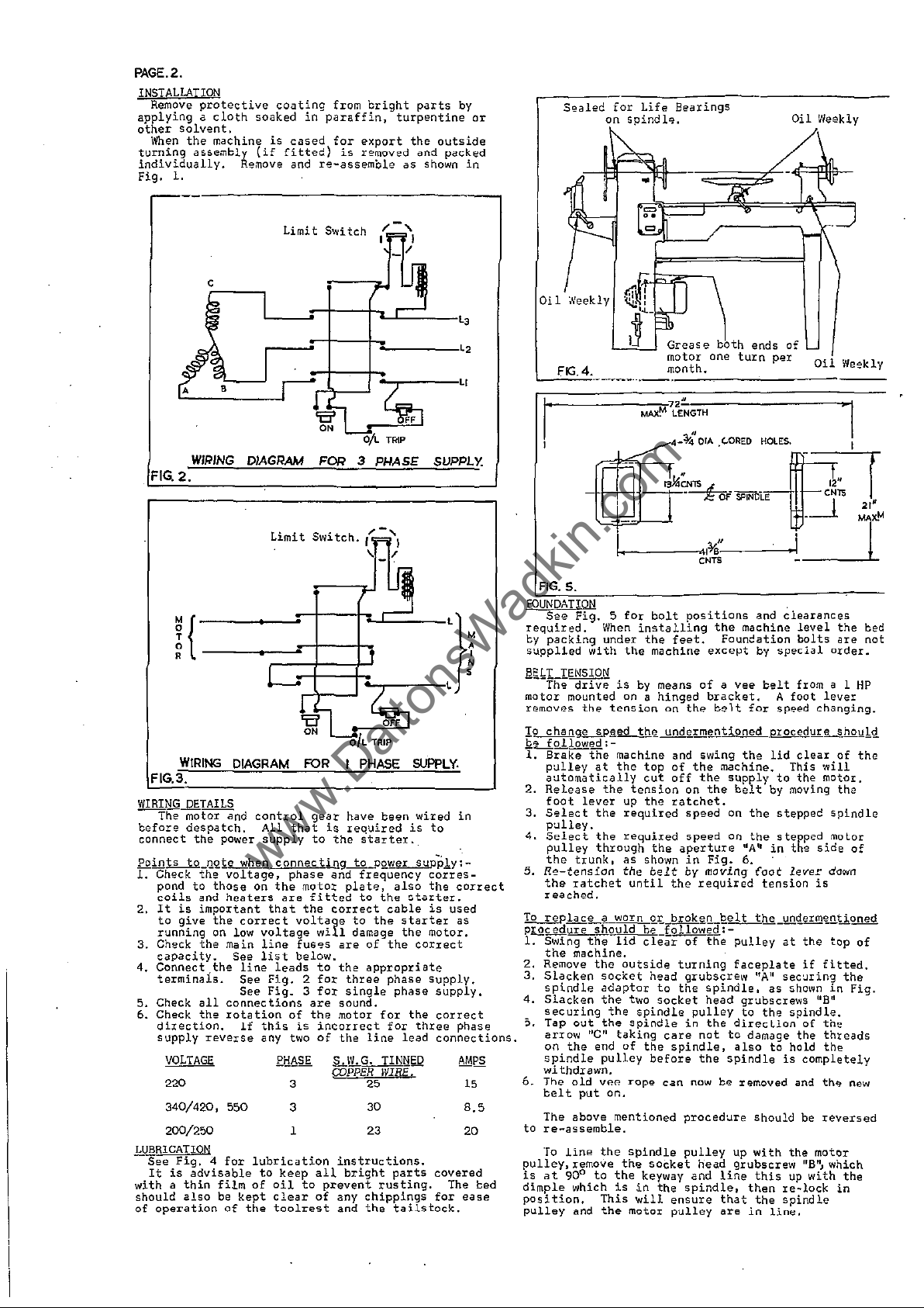
FOUNDATION
See
required.
by
supplied
llokLIENSIO~
motor mounted on a
removes
~o
&:L........Q....lowed:-
1.
2.
3,
4.
5.
To
pI.Q.cedure
1. Swing
2.
3.
4.
~.
6.
to
pulley,
is
dimple
position.
pulley
Fig. 5 for
with
drive
the
When
under
packing
The
cfhalngiL..§.pged
Brake
the
pu.lley
au.tomatically
Release
foot
Select
pulley.
Select
pulley
the
Re-tension
the
reached.
replac!L~Q.:Lbrok~!Le.elt
the
Remove
Slacken
spindle
Slacken
securing
Tap
arrow
on
spindle
wi
The
bel t put
The above mentioned
re-assemble.
To
at
at
the
lever
the
the
through
trunk.
ratchet
should
the
machine. .
the
socket
adaptor
the
out
the
"c"
the
end
pulley
thdrawn.
old
VP.P.
line
the
remove
900 to
which
This
and
the
bolt
installing
the
is
by
tension
th~
machine and swing
the
tension
up
required
required
as
the
until
lid
outside
two
the
spindle
spindle
taking
of
Tope can
on.
positions
the
feet.
machine
means
of
hinged
on
the
unde~!tQtioned
top
of
cut
the
shown
bl:!
clear
the
the
off
the
on
ratchet.
speed
speed
the
aperture
in
belt
by
the
required
_f.ollowed: -
of
turning
head
grubscrew
to
the
socket
pulley
in
care
not
spindle,
before
the
the
Fig.
moving
the
spindle.
head gr'Jbscrews liB"
the
now
procedure
spindle
the
the
is
will
motor
in
pulley
socket
keyway and
the
ensure
pulley
head
spindle,
the
Foundation
except
a Vee
bracket. A foot
helt
machine. This
supply
on
on
faceplate
direclion
to
also
spindle
be
lip
grubscrew
line
that
are
and
clearances
machine
for
the
belt
the
the
"A"
6.
pulley
to
damage
removed
then
in
level
the
bolts
by
special
belt
from a 1
speed
changing.
'procedure
lid
clear
to
the
by moving
stepped
stepped
in
the
side
(oot
lever
tension
the_llilq~enlioned
"A
as
the
at
l
sec'Jring
'
shown
spindle.
the
to
hold
is
is
the
if
of
completely
and
Should be
with
the
motor
this
the
liB", which
up
with
re~lock
spindle
lin~.
bed
are
not
order.
HP
lever
shou!.<:!
of
the
will
motor.
the
Spindle
molar
of
down
--
top
of
fitted.
the
in
Fig.
th~
threads
the
th~
new
reversed
the
in
 Loading...