

Wadkin bursgreen User Manual
www.DaltonsWadkin.com
www.DaltonsWadkin.com
www.DaltonsWadkin.com
12"
www.DaltonsWadkin.com
www.DaltonsWadkin.com
www.DaltonsWadkin.com
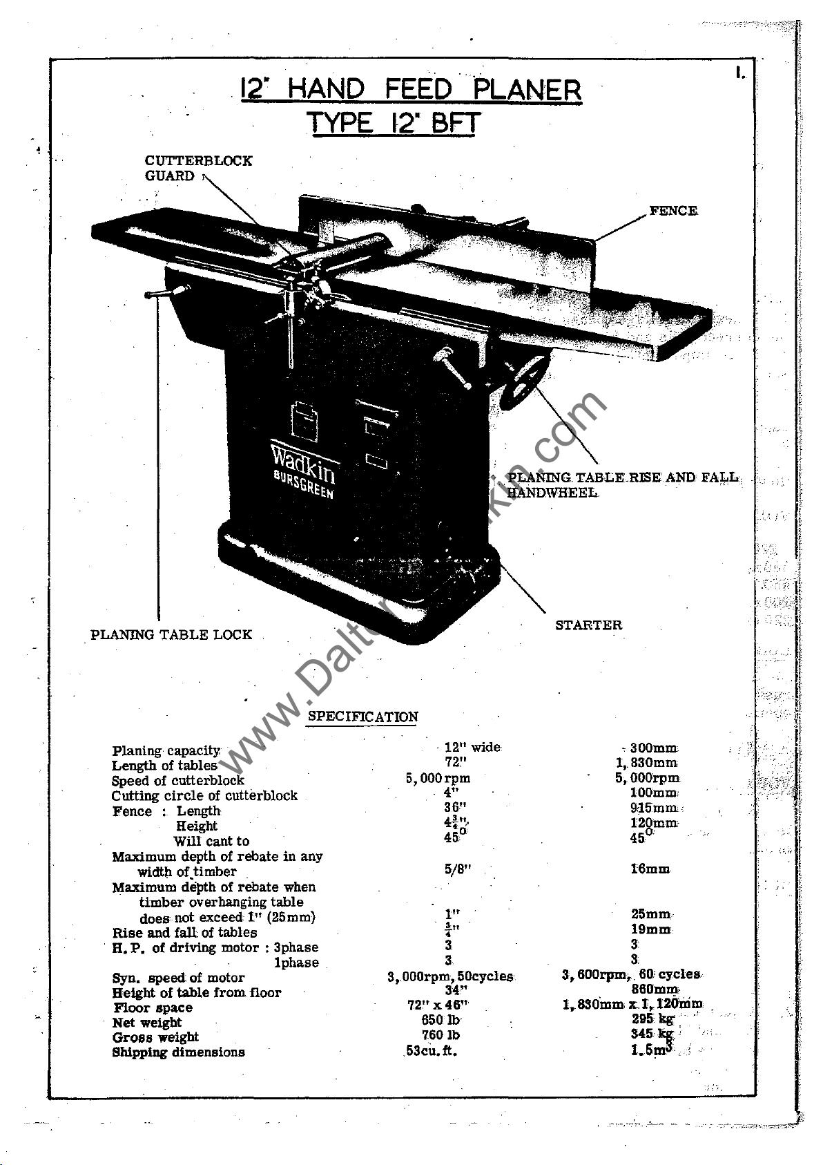
HAND
FEED
I.
PLANER
TYPE
12"
BFT
..
PLANING..
HANDWHEEL. . .
TABLE
..
RISE.AND FALL.
PLANING.
Planing
Length
Speed
Cutting
Fence
Maximum depth of
Maximum de'tJth of
Rise
H.
Syn.
Height
Floor
.
Net
Gross
Sbipping
of
widtlt
timber
does
and
P.
of
speed
space
weight
weight
TABLE
capacity
of
tables
cutterblock
circle
: Length
Height
Will
of.timber
not
faU
driving
of
table
dimensions
LOCK
of
cutterblock
cant
to
rebate
rebate
overhanging
exceed
of
of
1"
tables
motor : 3phase
motor
from
floor
SPECIFICATION
in
any
when
table
(25mm)
Iphase
.
12"
wide
72"
5, 000
rpm
4"
36"
4~tll
0
45.
5/8"
In
.!n
•
3
3
3,000rpm,50cycles
34"
x46
650
lb
7601b
n
72'"
53cu.ft.
STARTER
1,.
5,OOOrpm
3,
600rpm,
1
•.
630mm
,300mm
830mm
lOOmm
g.15mm
120mm
45°
16mm
25mm
19mm
3:
3:
..
60;
cycles,
860mm
x.
1,.
120mm
295 kg;.
345
kg
3
1.5m
.
,.
"'.
i
,
2.
www.DaltonsWadkin.com
www.DaltonsWadkin.com
www.DaltonsWadkin.com
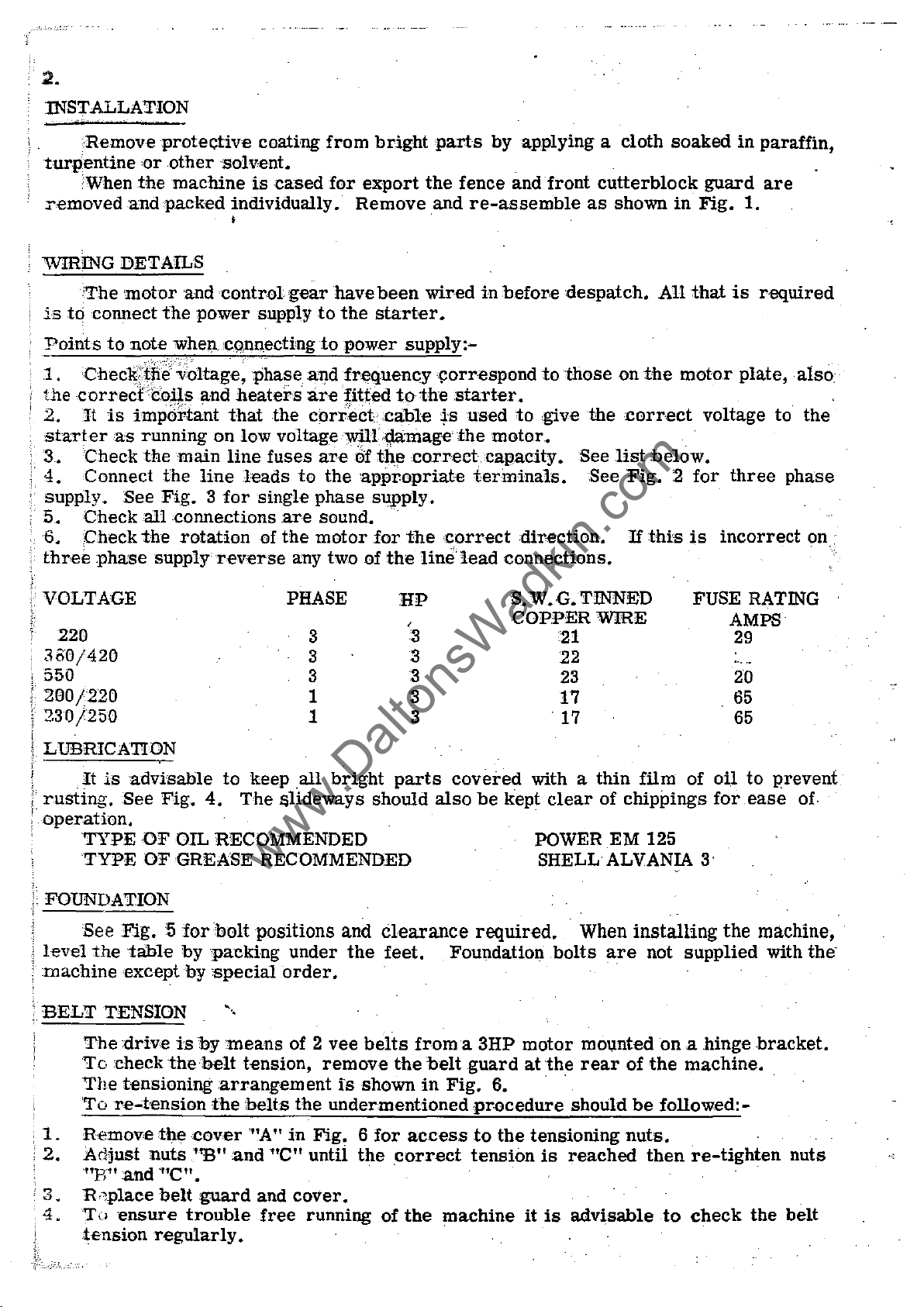
:rnSTALLATION
~RemoveproteGl:ive
turpentine
When
~r€movedandpack€d
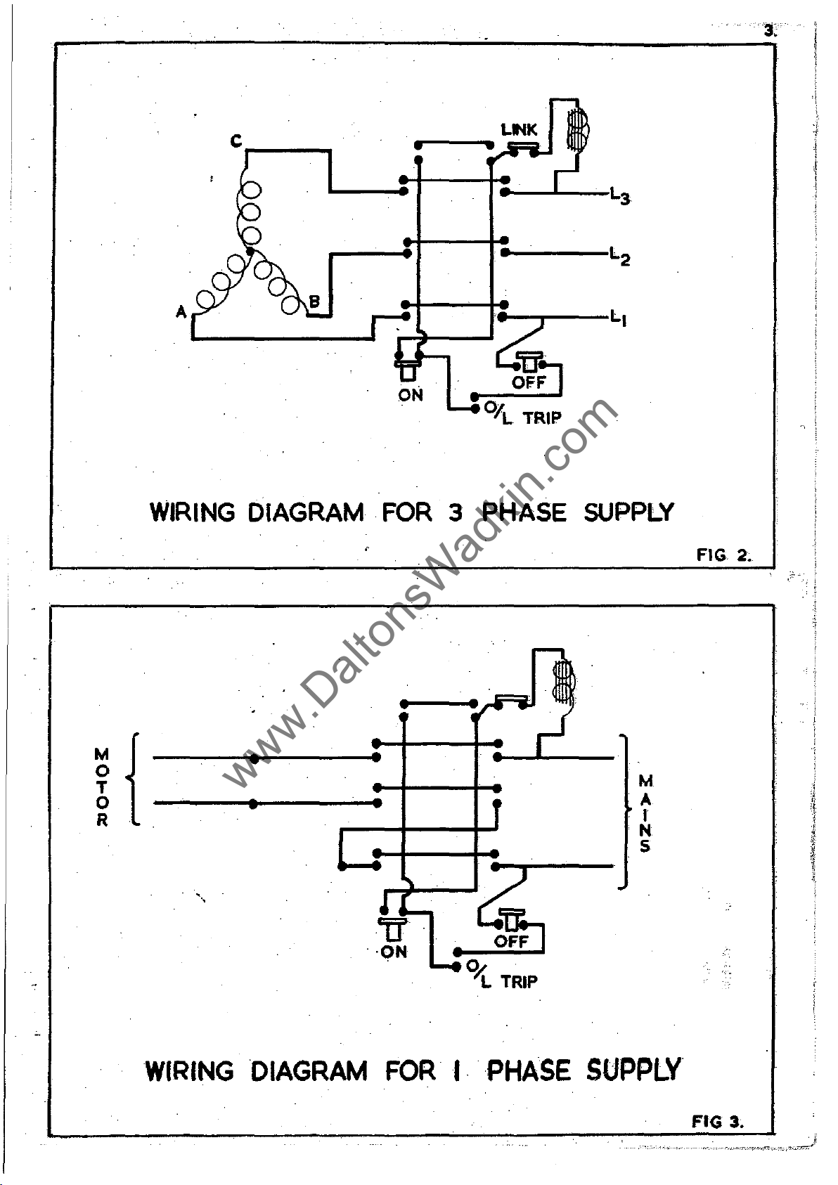
WIRING DETAILS
~The
is
to
connect
Points
motor
to
note
or
other
the
machine
and
the
power
whell,cq,lUl,ectingtopower
1.Chec~1:fi~;~ltage~
the
2.
start
3.
4.
~
supply.
5.
~
6.
three
correct
It
eras
Check
Connect
Check
Check
phase
cogs
is
important
running
the
See
all
the
supply
and
main
the
line
Fig. 3 for
connections
rotation
coating
sol
v€nt.
is
cased
individually.
,
control
gear
supply
phase
heaters
that
the
on
low
voltage')Vilr'l1amag€
line
fuses
leads
single
are
of
the
reverse
any two of
from
to
for
export
Remove
have
the
bright
the
been
wired
starter.
parts
fence
and
re-assemble
~
in
by
supply:-
alldfr~quency\!orrespond
are
fitted
carrect;cable
are
to
the
phase
sound.
motor
to
the
starter.
is
used
the
Of
thecorrecicapacity.
'appropriate
terminals.
supply.
for
the
'correct
the
line
lead
applying a
andiront
before
to
nespatch.
to
those
give
motor.
direction.
connections.
cloth
cutterblock
as
shown
on
the
the
correct
See
Hst
below.
See
Fig. 2 for
If
this
soaked
in
All
that
motor
is
in
paraffin,
guard
Fig.
are
1.
is
required
plate,also~
~
voltage
incorrect
three
to
the
phase
on ;
VOLTAGE
220
330/420
550
200/220
230/250
i
!.
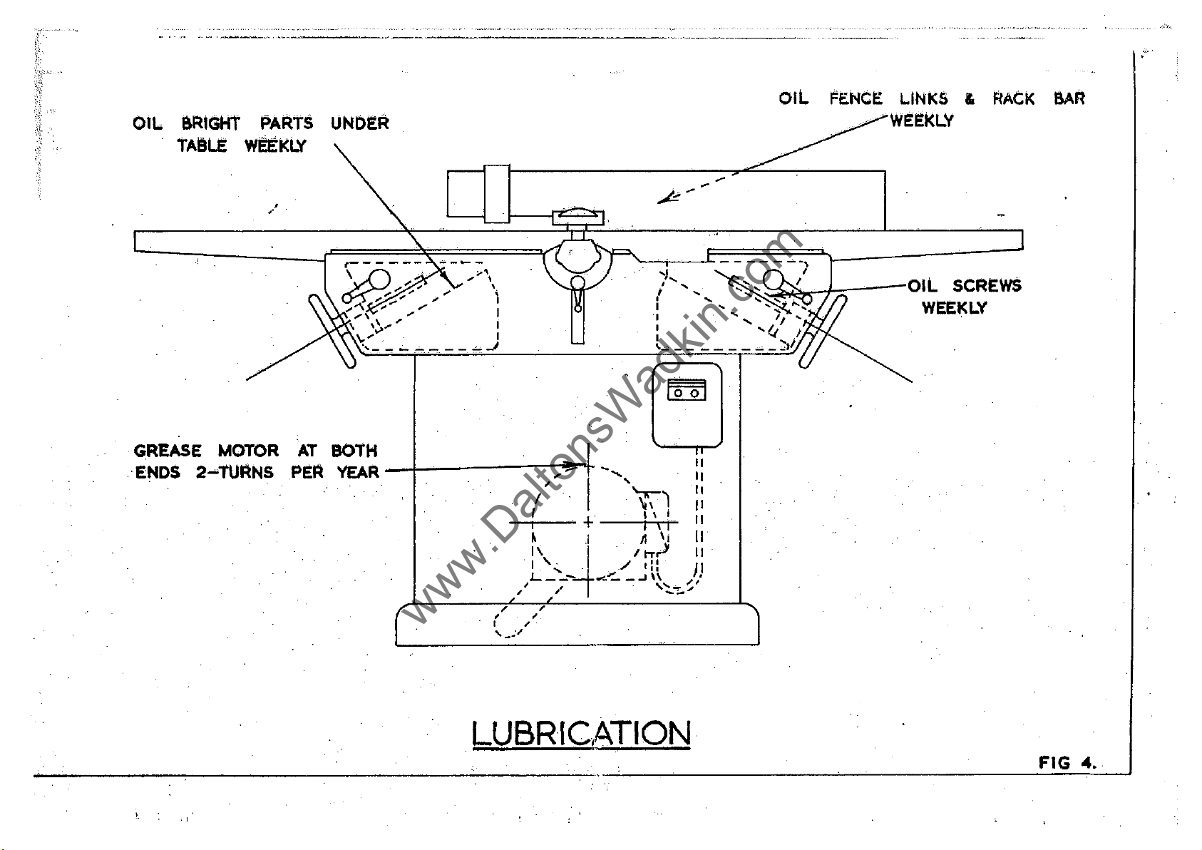
L1JBRICATION
, .
;'
.
1 FOUNDATION
1
It
is
rusting.
operation.
TYPE
TYPE
See
l.evel
the
machine
BELT
TENSION
The
To
check
The
advisable
See
Fig.
OF
OF
Fig. 5 for
table
except
drive
tensioning
Tore..;tension
PHASE
3
3
3
1
1
to
keep
.all
bright
4.
The
&lideways
OIL RECOMMENDED
GREASE RECOMMENDED
bolt
positions
by
by
is
by:means
the
belt
packing
special
-',
under
order.
of 2
tension,
remove
:arrangement
the
belts
the
should
and
Clearance
the
vee
belts
fs
shown
undermentioned
HP
,
'3
'3
3
'3
3
parts
feet.
from
the
covered
also
be
required.
Foundation
a BHP
belt
guard
in
Fig.
procedure
S.
W.G.TINNED
COPPER
'21
22
23
17
~
17
with a
kept
clear
POWER
SHELL ALVANIA
When
.bolts
motor
at
6.
the
.'
shouln
mounted
rear
WIRE
thin
film
of
chippings
EM
installing
are
of
be
FUSE RATING
AMPS
29
20
65
65
of
oil
to
prevent
for.ease
125
3'
the
machine,
not
supplied
with the'
on a .hingebracket.
the
machine.
followed:-
of·
.
,1.
,2.
3.
4.
Remove
Adjust
""E"
and
R
"place
To
'ensure
tension
the
cover
nuts
''E''
'nc
n • . . "
beUguard
trouble
'''A''
in
~and
nc"
and
cover.
free
Fig. 6 for
untii
the
running
access
correct
of
the
to
the
tension
machine
tensioning
is
it
is
regularly.
nuts.
reached
advisable
then
to
re-tighten
check
the
nuts
belt
A
www.DaltonsWadkin.com
www.DaltonsWadkin.com
www.DaltonsWadkin.com
cr--_
....
LIIIK
....---
ON
M
o
T
o
R
WIRING
.
"\
DIAGRAM·
•
•
•
•
FOR
•
3 PHASE
SUPPLY
M
A
. I
N
S
FIG
2~
WIRING
DIAGRAM
FORI··
PHASE
SUPPLY
FIG 3.
·
www.DaltonsWadkin.com
www.DaltonsWadkin.com
www.DaltonsWadkin.com
...
---
.......
----
..
-.--.
._---------_
.....•
_---.-----
...
--
...
-
\
.'
OIL
GREASE
ENDS 2
aRIGHt
TABLE
PARTS
wEEKLY
MOTOR
.....
TUANSPEA
AT
UNDER
BOtH
YEAR
-+------,~"I-
, '
-,
/ \\1::
r + 1\:
~
1\
"",
L
" /
, ,
, ,
I , .
,-~.'"
__
.i
4
-
-
..:'.~_.J\\
./
A
lIT
I::
I,
..
)
~/
''':::..'''!..
....
::
11
11
11'
JI
OIL
FENcE LINKS &
WEEKLV
RACK
BAR
LUBRICATION·
FIG
04
•.
 Loading...