

Wadkin BSW 26 inch Parts Manual
o
www.DaltonsWadkin.com
www.DaltonsWadkin.com
www.DaltonsWadkin.com
c
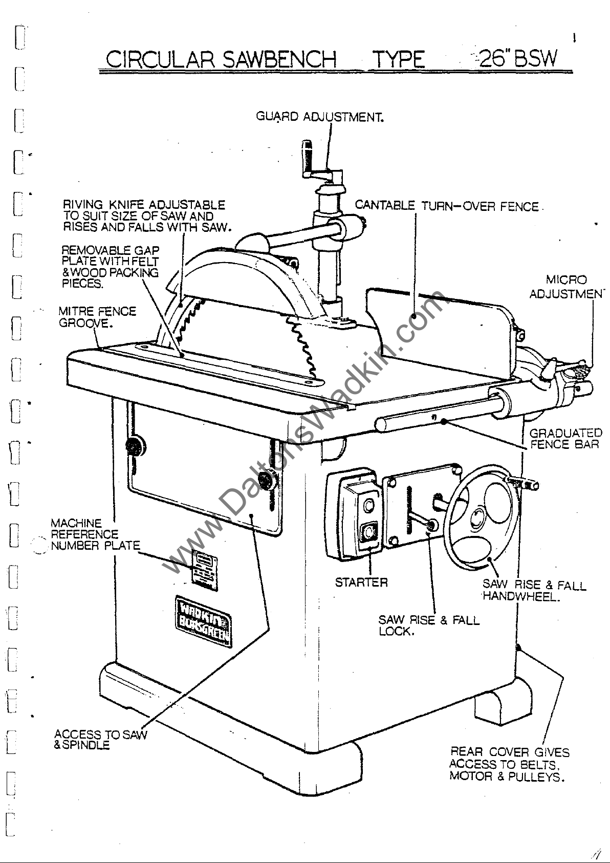
CIRCULAR
SAWBENCH
TYPE
-:-26"
BSW
[
c'
C'
r
L
c
o
o
RIVING KNIFE ADJUSTABLE
TO
SUIT SIZE
RISES
REMOVABLE GAP
PLATE
&
WOOD
PIECES.
AND FALLS
WITH FELT
PAC:KII\IG
OF
SAW
IAln-U
GU~RD
ADJUSTMENT.
F=:i-2-
CANT ABLE
.....
TURN-OVER
FENCE.
MICRO
ADJUSTMEN'
fJ'
fJ"
1
0
o
r
[
t
MACHINE
.-,
REFERENCE
NUMBER PLATE
~
~
:cr=~-r~!!::::~~::::~~GRADUATED
...
FENCE BAR
~
STARTER
SAW
LOCK.
RISE
& FALL
SAW
HANDWHEEL.
RISE & FALL
[
ACCESS
&SPINDLE
TO
[
[
REAR
ACCESS
MOTOR
COVER
GIVES
TO
BELTS,
& PULLEYS.
SECTIONS
www.DaltonsWadkin.com
www.DaltonsWadkin.com
www.DaltonsWadkin.com
,
i
Ii
O
,
,
l,!
"
C
.>
SECTION A
SECTION 5
SECTION C
SECTION
SECTION E
SECTION A
S8CTION 5
SECTION C
, -,
D
.~
ILLUSTRATIONS
FIG
Al
FIG
Bl
FIG
52
FIG
Cl
FIG
C2
FIG
CJ
SPECIFICATION
INSTALLATION
DESCRIPTION
MAINTENANCE
SPARE PARTS
26'
BSW
CIHCULAR
WIHL"IG
FOUNDATION
CANTING'FENCE
FENCE ALIGNMENT PO'L'lTS
RIVING
DIAGH.Ul
lL'IU'E DETAIL
& OPERATION
LIST
SAWl:l&"fCHES
(J
PHASE)
PLAN
CONTROLS
0;'
1
Oi,
e:
'"
"
j
('Oo
D
~'
!'J
..
C
,-
,I'
i
.r
:
1-
C
SECTION D
'.
FIG
FIG
FIG
FIG
FIG
FIG
FIG
.
FIG
FIG
FIG
c4
C4A
CS
c6
C7
c8-Cll
Dl
D2-DJ
D4-D12
D1J
RISE
RIVING
MITRE
MITRE FENCE STOP
SA....PACKIN:GS
OPERATION OF OPTIONAL FEATURES
SAI{
DELT
SAW
LUBRICATION
~'1D
FALL
lL'IIFE DETAIL
FENCe
SPDIDLE
TENSIONL'iG
MAINTENANCE
CONTROLS
ASS~lBLY
ROD
POSITIONS
.1'1
Dd
, )
Cl
I
[
.~
• J
, .
Cl
L
~

[
www.DaltonsWadkin.com
www.DaltonsWadkin.com
www.DaltonsWadkin.com
[
3
[
[
[
[
c
Haximum
Maximum
Size
of
Table
Hax.
Fence
Fence
height:-------------------------------------------
distance
dimensions---------------------------------------
cants
SPECIFICATION
diameter
saw
projection----------------------------
table--------------------ll090
up
of
saw
-----------------
saw
to
fence--------------------------------
to----------------------------------
26"
650
rmn
10"
255
rmn
43" x 34"
x 860
34"
865
rmn
20"
SOO
rmn
21"
X
x 190
S35
o
4S
nun
7~1t
rmn
o
o
o·
[
[
[
Rise
and
fall
Speed
Horse
Diameter
Diameter
Net
Gross
Shipping
of
saw
power
of
of
weight----~---------------------------------------
weight
dimensions--------
of
saw
spindle------------------------------
spindle---
of
motor-------------------------------------
saw bore ___________________________________ _
driving
_
_________________________________
__________________
pin--------
_______
____________________________ _
~----------------
S"
130
rmn
16S0
rpm
10
45
rmn
12
rmn
1000
lb
4S0
kg
12901b
590 kg
52
cu.ft
1.5
m3
[
[-
L

4
www.DaltonsWadkin.com
www.DaltonsWadkin.com
www.DaltonsWadkin.com
SECTION B
Cl
Installation:
Remove
"applyin~
Wiring:-
therefore
supply
POINTS
1 -
Check
2 _
It
correct
DAHAGE
J -
Check
1.
_
:;onnect
5
Check
6 _
Check
any
The
a
rrotor
to
TO
is
two
-
protective
cloth
all
the
NOTE
volta~e,
important
voltage
HOTOR.
main
line
all
spindle
of
soaked
and
that
starter,
WHEN
line
leads
connections
the
anti-ru~t
in
control
i~
required
or
CONNECTING
phasp.
that
to
fu~es
rotates
line
and
the
the
to
leAd
coating
paraffin
gear
i~olator
starter.
are
cnrrect
are
in
have
to
be
where
TO
POWeR
frequency
correct
of
correct
terminals
sound.
correct
connAct
or
other
been
done
SUPPLY.
cable
RUNNING
direction.
ion~.
from
fitted.
capacity.
bright
~olvent.
wired
i~
to
is
used
ON
(SEE
part~
in
before
connect
to
deliv
LOW
VOLTAGE
WIRING DIAGRAH).
If
not
by
de~patch,
the""main~
.. r
the
WILL
reverse
;
C
o
o
o
FAILURE
1 -
2 -
J -
4 -
;>"liJPPAGE flURIl'IG
1 -
~ -rtl~e5
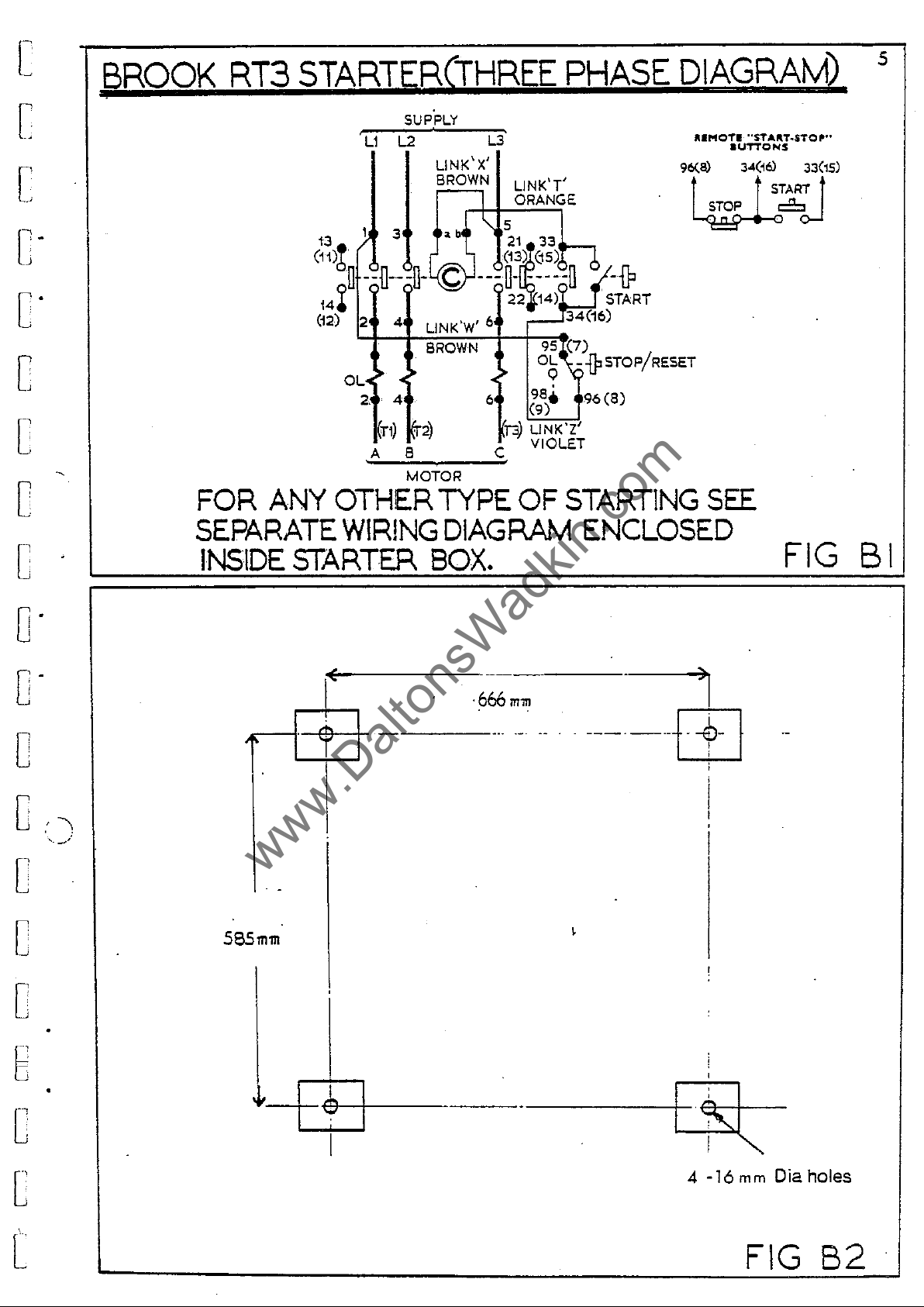
Foundation:-
mounting
floor
cement.
artequate.
TO
Fuses
Isolator
Lock
Supply
Ov
..
rloarls
jf
automatic
The
and
For
START:-
1,1ave
switch
off
or
root
ha\'~
machine
into
rag
mounting
(see
blown
stop
available
OPBR4TTON
have
blown.
concrete,150
bolts
Fig.
ha~
tripned.
they
should
fitted,
BZ.)
or
button
~il1
on
have
not
been
(",her.
at
m"chlne.
&
~'AlL1]RS
r\,-set
be
levelled
to250
after
wood
not
heen
closed.
fitted)
11'
ll:l.nrl
after
square
which
~loors
fitted.
1V
i,ESTART:-
re-set,
and
coach
has
set
a
short
bolted
hola~
the
holes
bolts
not
been
hy
period.
down
should
dhould
will
rele~sed.
pressin~
firmly.
be
cut
be
found
be
!",ttrm.
For
in
run
the
with
o
1
0
1
0
j
C
c:
i
'
!_
J
0
b-
C
1
!"
0
[
www.DaltonsWadkin.com
www.DaltonsWadkin.com
www.DaltonsWadkin.com
BROOK
RT3
STARTER(THREE
PHASE
5
DIAGRAM)
[
[:
c-
c-
c
[
[
c
-,
13
(11)h
14~
(12)
FOR
ANY
OTHER
SEPARATE
INSIDE
STARTER
SUPPLY
,
L1
L2 L3
LlNK'X'
BROWN
);
3 • b
il
--n---o-
2 4 LlNK'W' 6
>
OL~
2 4 6
A B C VIOLET
~~~~
c
BROWN
~
~
MOTOR
TYPE
WIRING
DIAGRAM
LlNK'T'
l ORANGE
"5
21
(13~e5)~
---0-
22 14) . START
>
• 9
j"3)
OF
BOX.
33
-----0
9S~~7)
OL
98,
(9)
LINK'Z'
-{P
34(16)
--jpSTOP/RESET
96(8)
START1NG
ENCLOSED
RlMOTI
96<a)
t
~6oJ
"ST"'''T.STO'''
aUTTCNS
34(~61
_.___
t S
S1TAR.T
SEE
33(15)
t
FIG
B I
o·
o·
0
D
'\
-'.
0
0
D
E
[
[
---/
.---+-e!-+
585'111'111
-l-
I
E
l
I
!
I
----._-
I
)1
-666
m,.
--
-.
- .
-----+~-l
i
,
-
.
I
~l
4 -16
mm
Dia holes
[
FIG
B2

SECTION C
www.DaltonsWadkin.com
www.DaltonsWadkin.com
www.DaltonsWadkin.com
o
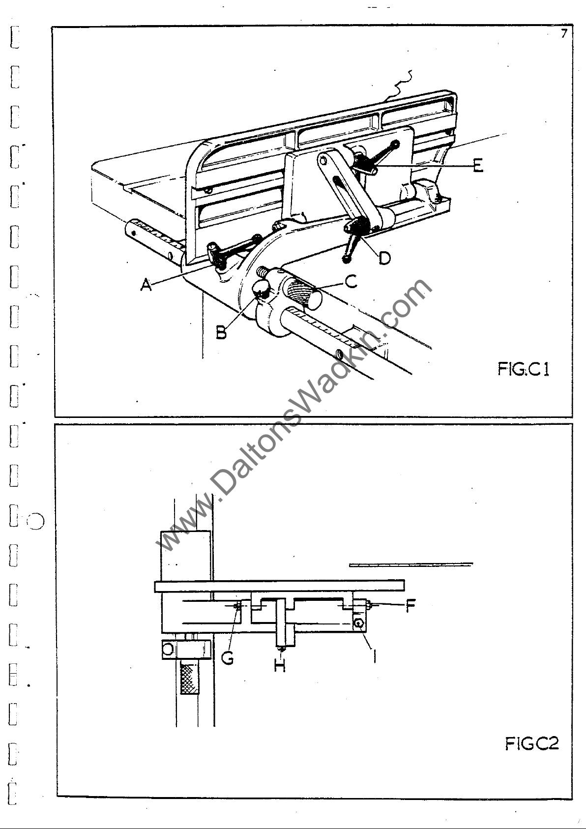
CANTING
9,UICK
orated
proceedure:-
1.
2.
J.
FINE
provision
ment
1.
2.
J.
CANTING,-
1.
2.
J.
FENCE
table
be
slot
locking
NOTE:.For
ADJUSTI!ENTj-
into
Unlock
Slide
indicated
Lock
ADJUSTMENT'-
feature.
Ensure
Turn
the
required
Lock
Unlock
Unlock
edge
Lock
POSITIONING,in
used.
in
&
RIP
FENCE
it.
lever
the
fence
against
lever
knurled
fence
lever
To
of
lavers
the
lever'E'will.
'A:
i~
made
lever
along
~etting.
'K
cant
leva·r
lever
the
order
By
unlocking
back
crosscutting
CONTROLS
The
To
adju~t
'A:
and
along
the
firmly
After
for
To
operate
'A'
is
UNLOCKED
hand
firmly.
'D'
'El
plate
\ I \ I
D
to
~crew
the
fence
and
allowing
lies
and
E
The
compen~ate
of
the
:fi~
fence
~crew
to
adjusting
precise
rule
follow
allow
firmly.
fence
lever
swing
~lides
the
'B'
the
bar
pointer
~ecure
follow
'C'
in
bar
fence
fence
flat
plate
for
'E"
fence
the
fence
fence
on a round
fence
(Fig.
~etting
and
direction
to
under
on
the
to
follow
C.l.)
until
on
the
in
position.
the
fence
by
under
~crew
or
away
mentioned
to
pivot
plate
the
table
is
designed
different
plate
the
required
firml.y
over
bar
the
the
required
fence
by
operating
mentioned
'B'is
to
the
LOCKED
required
from
over
drop
~urface.
~izes
maybe
in
pl.ace.
rul.e
with
under
dimen~ion
bracket.
the
above
the
proceedure.
firmly.
in
the
saw
proceedure
to
required
down
to
slid
position,
of
bar
until
slide
saws
along
to
a
rule
mentioned
method
fine
order
cl.ear
adju~t
(Fig.
to
and
to
(Fig.C.l.)
angle.
the
alon~
which
..
dovetail.
a:fter
incorp-
is
C.l.
draw
the
lower
the
may
which
the
)
table
l
O
-,
1
Cl:·
~,
·:·
It
6
1
, 1
0.
,
,
"
0·
,
I'
.1
0
I
Or
FENCE
finely
screws
uses,
pl.ace
outlined
POINT
to
be
POINT
between
POINT
wil.l.
the
table
POINT
parallal
SETTING
On
despatch
adjusted
at
points
and
should
from
underneath:-
F.-
set
paral.el.l
G;-
centres
H,-
not
all.ow
when
I;
-
to
A~D
for
constant
is
an
i .. a
F
is
a
the
~et
ie
al~o
the
tabl.e
ALIGNING,-
:from
the
accurate
F.G.H.I.
onl.y
eccentrical.ly
true
jacking
be
u ..
e.
to
the
centre
and
G.
fence
correctly.
a
jacking
for
re-eet
point
to
works
cutting
(FIG
The
sav,
which
be
true
the
movements
by
the
C2).
to
~eperate
turned
or
which
pull.ed
point
cant
Theee
co~pen~ate
u~es
centre
to
be
~et
al.lows
provides
up
of
provision
adjustments
for
of
which
in
sl.acknesa
a
further
the
fence
wear
the~e
al.lows
or
out
to
positive
than
have
of
the
have
which
point
as
90
..
the
required.
be
re~oved
~top
degrees
F
and
been
~etting
seperate
may
are
take
as
fence
which
to
G
)
@
Cl
f
i J
O
I
~.I
Ul
nf
Uj
,
··!,
; :
C
"
[
www.DaltonsWadkin.com
www.DaltonsWadkin.com
www.DaltonsWadkin.com
[
[
C-
O
0
C
7
0
C
O·
0
C
lOO)
C
.-../
0
['
-'
.
FIG-Cl
[
J
E
.
[
[
[
FlGC2
8
www.DaltonsWadkin.com
www.DaltonsWadkin.com
www.DaltonsWadkin.com
RISE
lowered
'A'
varied.
handle
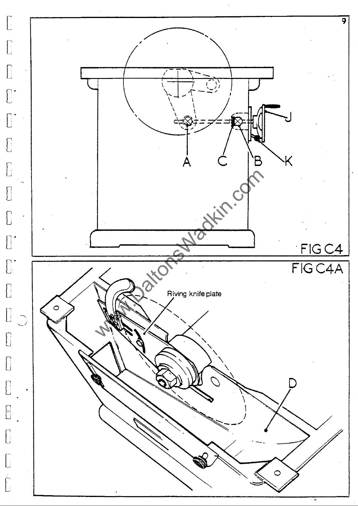
points
race
important
11"
and
AND
FALL
By
turning
between
specification.
It
'K'
is
The
C
A.
&
is
that
rise
B.
fitted
that
the
CONTROLS:-
handwheel
the
maximum
Under
is
important
locked
and
(FIG
to
the
wu"t
firmly
fall
C4.)
give
pivots
'J'
no
after
handwheel
At
free
and
race
is
(fig.
and
minimum
circumstances
operating
before
is
the
handwheel
ro,tation
"crew
oiled
C4
)
running
connected
when
are
accordin
the
ooaition
should
the
the
end
in
cleaned
....
saw
rise
saw.
through
of
use.
and
to
may
as
this
and
the
the
given
luhricated
be
r~ised
in
dimension
fall
pivoted
screw
It
maintenance
is
that
a
therefore
or
section
lever
yolks
thrust
regular-
be
at
sCheduleD!'
o
, )
,···1
.,
0
.,
1
Oil'
J
,
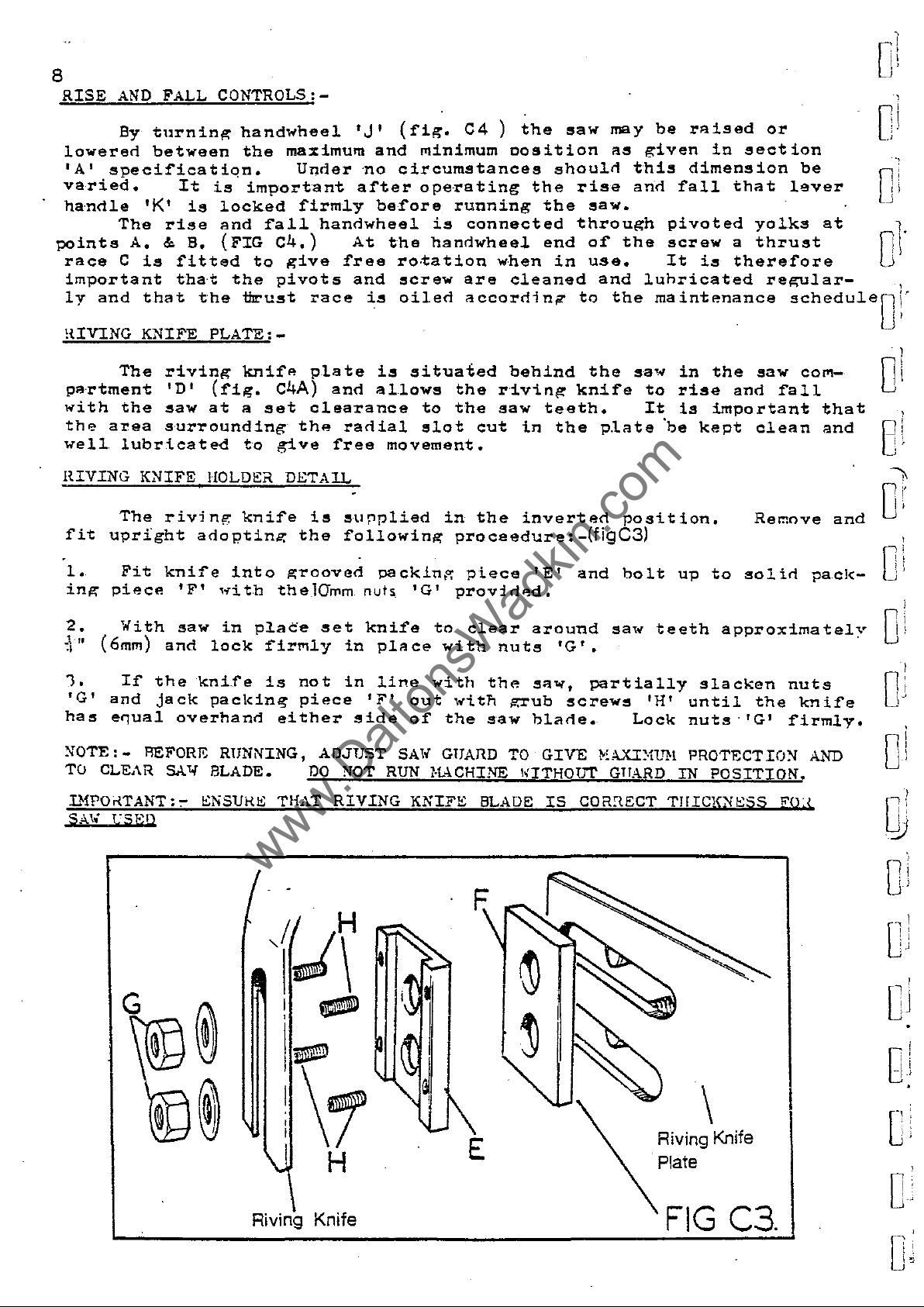
!UVING
partment
,.,i
th
th",
well
HIVING
fit
1.
ing
2.
J'II
.,
1.
'G'
ha"
XOTE: - REFORE RUNNING,
TO
KNIFE
The
the
area
lubr:lcated
KNIFE
The
upright
Fit
piece
With
(6mm)
If
the
and
CLEAR SA"f BLADE.
jack
e.,u~l
PLATE:-
riving
'0'
saw
s·urrounding
riving
knife
'F'
saw
and
'knife
overhand
knife
(fig.
at
a
t·o
HOLDER
knife
adcptinO':
into
'~ith
in
lock
packing
set
place
firmly
is
c4A)
give
DETAIL
g-roovad
thelGmm
either
plate
and
clearance
the
radial
free
i"
"uflplied
the
following
set
in
not
piece
ADJUST
DO
in
NOT
is
allows
movement.
packin!,:
nuts
knife
place
line
'F'
side
RUN
situaied
the
to
the
slot
in
proceedure:
'G'
prov:lded.
to
with
with
out
,~itn
of
the
SAl,
GUAnO
K~CHINE
cut
the
piece
clear
the
saw
behind
riving
saw
in
inverted
'E'
around
nuts
sa""
..:rub
blade.
TO
GIVE
IGTHOTlT
knife
teeth.
the
and
'G'.
screw"
the
"a'"
to
It
plate
-(figC3)
saw
partially
~,AXIXUH
GTTARD
'be
position.
bolt
teeth
'H'
Lock
in
the
saw
rise
is
up
IN
and
important
kept
slackan
until
nuts'
PROTECTIO!'l
clean
Remove
to
solid
approximatel::
the
'G'
POSITION.
CO<'l-
fall
1'acl<-
nuts
knife
firmly.
AND
that
and
and
Ol
, ,
,·i
, ,
O
. I
'·'
"
! i
0
, ,
'
\ i
0
1
!
,
11
0
I
0\
i \
'·1
0
DIPOi-{TANT:,.
SA"·
rSEI)
G
ENSUi-{E
THAT
,(~\
®
-
~
Riving Knife
\1
RIVING
-
H
KNIFE
BLADE
E
IS
COR,\ECT
TlfrCKflESS
\
Riving Knife
Plate
FIG
C3,
FO!
:
0
..
:V
·1
u
0
-,1
[jJ
DJ
-'
:
, j
C
,
0;
o
[
www.DaltonsWadkin.com
www.DaltonsWadkin.com
www.DaltonsWadkin.com
[
c
' .
[
-'
9
c-
c
[
o
C
0-
C-
C
A
I'<;V'r'V1 knife plate
J
K
. F1GC4
FIGC4A
[-':
... ~.J
c
[
[
6
[
[
[

10
www.DaltonsWadkin.com
www.DaltonsWadkin.com
www.DaltonsWadkin.com
HaUNTING
1.
SAWBLADES:-
When
Isolate
mount
machine
in..;
saws
the
und
erment
iancd
proceedure
sho
"In
be
.
t'ollo",ed:-
o
, ,
)
,
0'
j
.,
,
0;
2.
position.
3.
spindle.
4.
Check
especially
:'!pind1e
the
~.
fore
',OTE:-
DUE
which
setting,
quick
the
Remove
Remove
Select
saw
Chack
re·p1ac!nl?,
IHPO.<TA
...1!
ELECTRICS
TO
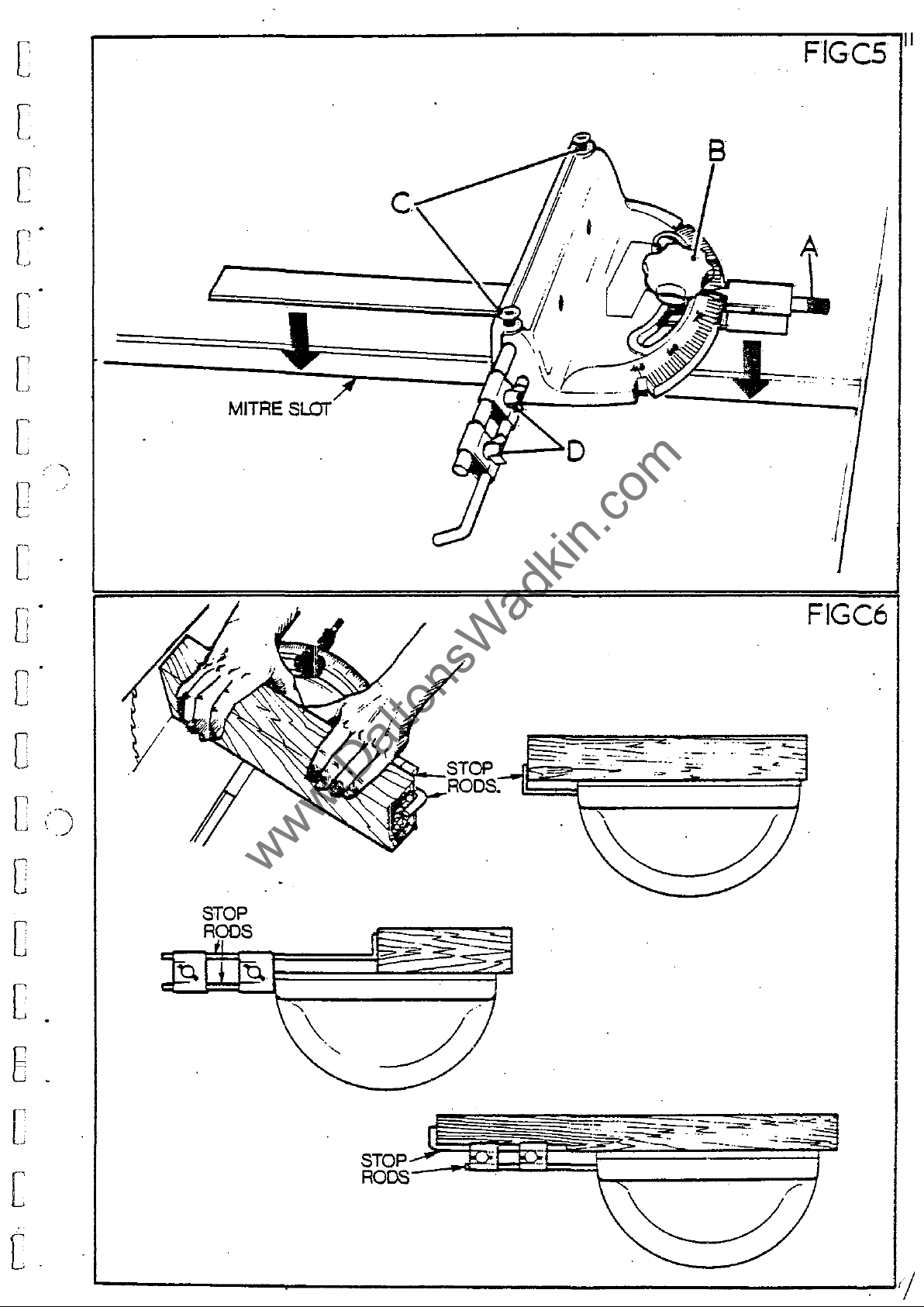
The
mitre
the
checki.ng
bore
..
'1T:-
IF
THE
mitre
should
and
s"tting
table
spindle
b1ane
h1ane
where
and
that
ENSURE
is
it
that
pin
the
the
insert
nut
required
in
good
will
the
hole
saw
f'lanl?,a
SPINDLE
(left
teeth
L
'I'll!, FL.\:-IGE OR S/\I.:
SAW
fence
RUN:-IING
fence
he
kept
a
positive
at
qOO
firmly
OUT-OF-TRUF.,
is
fitten
clean.
stop
and
in
and
raise
depending
conditi.on
he
gripped
face
centr
and
;<UNS
0
4S
to
any
the
sa",
hand
poi.nt
lock!n"
FACES
A
'A'
position.
thread)
on
ann
by
the
of'
the
hack
es . f'i t correctly
towards
UP
IN
COaRECT
ARE :-101'
into
the
the
scale
is
incorporated'
saw.
is
sr-i.ndl"
"nd
front
tYro
/?,roov"
of
work
free
t'irm.ly
provined
from
s"w
flange.
saw
flange
onto
the
front
with
'lIR"~CTIor;.
CL8A'I
providen
in
Th"
pl"stic
hOllsing
saw
which
dirt,
those
the
T1[IS
tn
innicate
the
into
flan~e
is
sawnust
Hount
i.s
clean
on
of
the
spindlp.
R;;;Fr~
CAN
""nnwheel
on
scale
TO
CA::SE
the
tbe
top
t'rom
to
be
done.
ann
,-;::urn.
saw
on
and
that
th e f'lanl"e.
machine
nut.
Sr~CT
VIJH1.A1'IO~
S""
accurate
to
'B'
be-
t"hle.
l;iv8
locks
the
0\'
..,
,
1
0
l1
:
i
, .
I'
O·
i
:
y
0
(fil':.
rods
"nd
(fi/r.
Accurate
C5.)
The
hy
the
'D'
ann
C6.)
rods
repetitive
are
two
sline
held
clamps
the
in
'D!
rons
cutting
the
Tb
into
'can
fenca
tha
he
with
adjust
po~ition
obtainen
the
the
sto!"
hy
us
..
of
thumb~crew~
rons
reqlJired
'c'
sl"cken
,,~
illustr"ted
the
stop
an~
cl"",ps
the
rods
stop
'C'
in
1
·!
[,j
D
, ,
"l.
(_1
O
oj
gJ
[]l
I
, .
"
, :
C
D·
[
www.DaltonsWadkin.com
www.DaltonsWadkin.com
www.DaltonsWadkin.com
[
[
' .
[
.
~
c·
c
[
MITRE
SlOT
B
FIGCS
I
I
11
c
[
o·
c
c
..
· ;
C
;
[
[
-';
.....
'
STOP
RODS
~.--.-
-.
.F"
,
I
FIGC6
[
E .
[
[
c.
 Loading...