


,
www.DaltonsWadkin.com
www.DaltonsWadkin.com
www.DaltonsWadkin.com
20
'..
. I
l;
(~·S·l,v
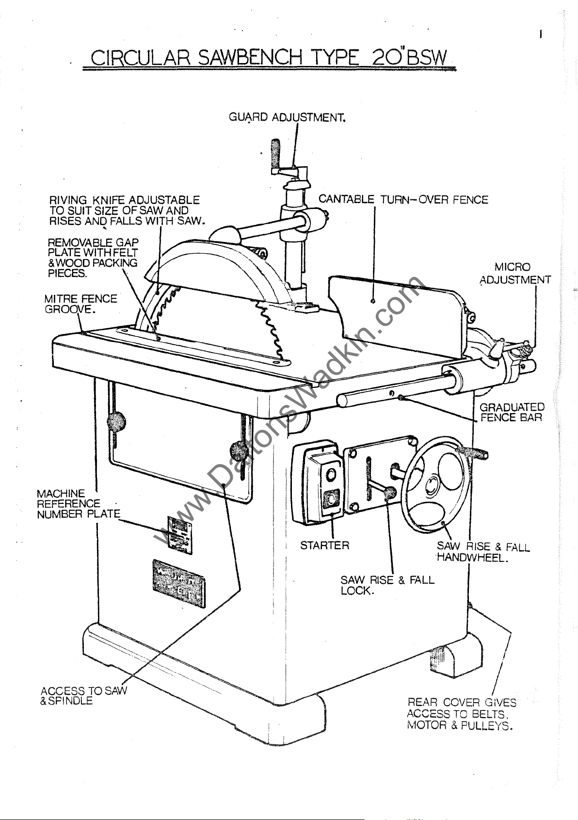
CIRCULAR
www.DaltonsWadkin.com
www.DaltonsWadkin.com
www.DaltonsWadkin.com
RIVING KNIFE ADJUSTABLE
TO SUIT SIZE
RISES AND FALLS WI . SAW.
REMOVABLE GAP
PLATE
& WOOD PACKING
PIECES.
WITH FELT
OF
SAW AND
"
SAWBENCH
TYP~
20'B§:tI
..
MICRO
~DJUSTMENT
MACHINE
REFERENCE
NUMBER
PLATE~
SAW RISE & FALL
, j LOCK.
I
REAR COVER GIVES
ACCESS TO BELTS.
MOTOR & PULLEYS.
2
www.DaltonsWadkin.com
www.DaltonsWadkin.com
www.DaltonsWadkin.com
SECTIONS
SECTION A
SECTION B
Sl£CTION C
SECTION
D
SECTION E
SECTION A
SECTION B
SECTION C
ILLUSTRATIONS·
FIG
FIG
FIG
FIG
FIG
FIG
A~
B~
B2
C~
C2
C3
5QOmm
SPECIFICATION
INSTALLATION
&
DESCRIPTION
OP~{ATION
MAINTENANCE
SPARE PARTS
BSW
CIRCULAR
WIRING
DIAGRA.H
FOUNDATION
CANTING
FENCE
FENCE
ALIGNMENT
LIST
SAW
(3
PLAN
CONTROLS
POINTS
RIVING KNIFE DETAIL
BENCH
PHASE)
SECTION
D
FIG
FIG
FIG
FIG
FIG
FIG
FIG
FIG
FIG
FIG
c4
C4A
CS
c6
C7
cB-Cll
Dl
D2-D3
D4-D12
D13
R1SE
AND
FALL
CONTROLS
RIVING KNIFE DETAIL
MITRE
MITRE FENCE STOP
SAW
OPERATION
SA\{
BELT
SAW
FENCE
ROD
PACKINGS
OF
OPTIONAL
SPINDLE ASSEHBLY
TENSIONING
MAINTENANCE
LUBRICATION
POSITIONS
j
FEATURES
3
www.DaltonsWadkin.com
www.DaltonsWadkin.com
www.DaltonsWadkin.com
Maximum
Maximum
Size
of
Table
Max.
Fence
Fence
distance
SECTION
SPECIFICATION
diameter
saw
table
height------------------------------------------------
dimensions-----------------------------------------------
cants
up
of
saw-----------------------------------------
proj
ection
-------------------------------------------------
saw
------------------------
to
fence
-----------------------
to----------------------------------------------
A
20"
500
175
36" x 38"
915
x 965
34"
865
600
17"
x
430 x
45°
mm
7"
mm
mm
mm
6"
150
mm
mm
Rise
Horse power
Diameter
Diame
Net
Gross
and
fall
of
saw
spindle-------------------------------
Speed
Shipping
of
saw
spindle------------------------------------------
of
motor-----------------------------------------
of
saw
bore--------------------------------------
ter
of
driving
weight---------------------------------------------------
weight---------------------------------------------------
dimensions---------------------------------------------
pin
------------------------------
100
mm
2200 rpm
7!
30
mm
12
mm
924
lb
420
kg
1230
lb
560
kg
46
cu.ft.
1.3
m3
4
www.DaltonsWadkin.com
www.DaltonsWadkin.com
www.DaltonsWadkin.com
SECTION B
Installation:-
•
Remove
applying
Wiring,,:
The
there£ore
supply
POINTS
1 -
Check
2 -
It
correot
DAMAGE
j
Check
4 -
Connect
5 -
Check
6 -
Check
any
FAILURE
a
motor
all
to
the
TO
NOTE
voltage,
is
important
main
all
spindle
two
TO
protective
cloth
and
that
starter,
WHEN
voltage
MOTOR.
line
line
connections
o£
the
START:-
anti-rust
soaked
control
is
required
or
CONNECTING
phase
that
to
the
(SEE
leads
rotates
LIST).
fuses
to
line
in
isolator
and
the
are
correct
are
in
lead
coating
paraf£in
gear
starter.
have
to
TO
£requency
correct
of
correct
sound.
correct
connections.
or
other
been
be
done
where
POWER
cable
RUNNING
terminals
direction.
£rom
solvent.
wired
is
to
£itted.
SUPPLY.
is
ON
capacity.
(SEE
bright
in
connect
used
LOW
parts
be£ore
the
to
deliv~r
VOLTAGE
WIRING DIAGRAM).
If
not
reverse
by
despatch,
mains
the
WILL
1
Fuses
2
Isolator
3 -
Lock
4 -
Supply
STOPPAGE
I -
Overloads
If
automatic
2 -
Fuses
VOLTAGE.
220
340/420
200/250
220
400/550
,Foundat:ion:-
have
switch
o£f
or
not
DURING
have
have
PHASE.
3
j
1
j
3
blown
stop
available
OPERATION & FAILURE
blown.
tripped.
they
or
have
ha~
not
button
will
CYCLES
50
50
50
60
60
at
re-set
not
been
(when
machine.
I£
hand
l!!:
5-S
11
11
u
JI
been
closed.
fitted)
TO
re-set,
after
£itted.
has
RESTART:-
a
short
S.W.G.
COPPER
17'
.20
1-+
17
21
not
set
by
period.
TINNED
WIRE.
been
pressing
released.
button.
~
5S
32
102
55
29
The
machine
mounting
rloor
cement.
adequate.
and
into
rag
For
mounting
(see
should
concrete.
bolts
Fig.
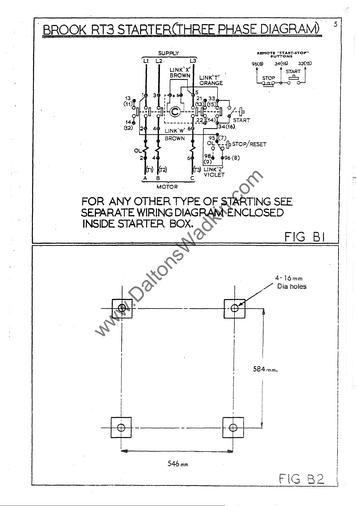
82.)
150
fitted.
on
be
lev~lled'and
to250square
after
wood
floors
which
coach
bolted
holes
the
bolts
should
holes
down
should
will
firmly_
be
cut
be
be
found
For
in
run
the
with
-
www.DaltonsWadkin.com
www.DaltonsWadkin.com
www.DaltonsWadkin.com
.t3BOOK
RT3
STARJER£THREE
PHhS
E
DIAGRAM).·
5
FOR
ANY
OTHER
SEPARATE
INSIDE
STARTER
SUP,PLY
r
L2
L1
,A
.L3'
LINK'X'
BROWN
B
•
MOTOR
TYPE
WIRING
BOX.
L1NK'T' I
ORANGE
C,
OF
STARTING
DIAGRAM
IU!,",OTI!
"STAftT·STO
IIUTTONS
SEE
ENCLOSED
..
••
I
I
!'\
j.I
FIG
4-16mm
/Diaholes
584mm.
I
~
f-
-
-
I'
\;
~
BI
546
mm
-
6
www.DaltonsWadkin.com
www.DaltonsWadkin.com
www.DaltonsWadkin.com
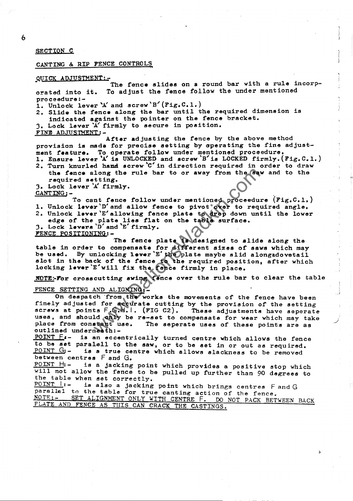
SECTION C
CANTING
&
RIP
FENCE
CONTROL~,
QUICK
ADJUSTMENT;-
•
orated
proceedure:-
L
Unlock
2.
Slide
indicated
3.
Lock
FINlD
provision
ment
1.
2.
3.
CANTING;-
1.
2.
3.
FENCE
table
be
slot
locking
ADJVS1HENI:-
reature.
Ensure
Turn
the
fence
required
Lock
Unlock
Unlock
edge
Lock
PQSIIIQltINq:-
in
used.
in
into
it.
lever
the
lever
is
lever
knurled
lever
To
tevor'D'and
lever'E'a11owing
of
the
levers
order
By
the
lever'E'Yill
"A:
fence
against
'A"
made
To
'A'
along
setting.
'K
cant
plate
D
" "
to
unlocking
back
The
To
adjust
and
along
the
£irm1y
After
for
operate
is
UNLOCKED
hand
firmly.
screw'
the
fence
lies
and
E
The
compensate
of
the
fix
£ence
screw'B
the
pointer
to
secure
adjusting
precise
follow
rule
follow
allow
flat
firmly.
fence
1.v.r
fence
the
slides
the
~
bar
'c'
in
bar
fence
fence
plate
for
'E'
fence
fenee
(Fig.
until
on
in
the
setting
under
and
direction
to
under
plate
on
di£ferent
the
to
the
on a round
follow
C.1.)
the
the
£ence
position.
fence
by
Gperating
mentioned
screw'B"is
or
away
mentioned
to
pivot
to
the
table
is
designed
pla
te
mayb'e
required
firmly
bar
with
the
under
req~ired
bracket.
by
the
above
proceedure.
LOCKED
required
from
over
drop
sizes
in
the
proceedure
to
down
surface.
to
of
slid
position.
place.
slide
a
rule
mentioned
dimension
method
the
fine
£irm1y.{Fig.C.1.)
in
order
saw
required
until
saws
alongadovetail
adjust-
to
and
to
.
(Fig.C.1.)
angle.
the
along
which
after
incorp-
is
draw
the
lower
the
may
which
N01'E:-J'br
FENCE SETTING
On
finely
screws
uses,
place
outlined
POINT
to
be
crosscutting
despatch
adjusted
at
points
and
should
from
underneath:-
F.,-
set
paraleli
constant
is
POINT G;-
between
POINT
will
the
POINT 1 t -
parallel
NOTFJ-
PLATE
H:-
not
table
AND
centres
is
allow
when
is
to
the
SET ALIGNMENT
FENCE
is
AND
ALIGNING: -
'from
for
F.G.H.I.
only
an
eccentrically
to
a
true
F
and
a
jacking
the
fence
set
correctly.
also
table
AS
THIS
swing
the
accurate
be
use.
the
centre
G.
a
jacking
for
ONLY
CAN
works
(FIG
re-set
The
say,
point
to
be
true
WITH
CRACK
fence
cutting
C2).
seperate
turned
or
which
which
pulled
point
canting
over
the
movements
to
compensate
to
allows
which
CENTRE
THE
the
by
the
These
uses
centre
be
set
slackness
prov1des
up
further
brings
action
F.
CASTINGS.
rule
DO
bar
o£
the
provision
adjustments
for
wear
of
these
which
in
or
out
a
positive
than
centres
of
the
NOT
to
fence
o£
points
allows
as
to
90
fence.
PACK
clear
have
the
have
which
the
required.
be
removed
stop
degrees
F
and
BETWEEN
the
table
been
setting
seperate
may
take
are
as
fence
which
to
G
BACK
,.I
~
7
www.DaltonsWadkin.com
www.DaltonsWadkin.com
www.DaltonsWadkin.com
FIG.Cl
IGC2
8
www.DaltonsWadkin.com
www.DaltonsWadkin.com
www.DaltonsWadkin.com
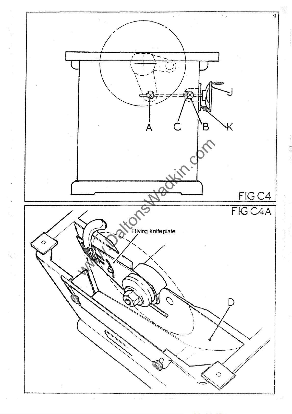
RISE
lowered
'A'
varied.
handle
~ints
race
important
ly
AND
By
specificati~n.
The
C
a~d
FALL CONTROLS:-
turning
between
It
'K'
is
rise
A. & B.
is
fitted
that
that
i.
loc.ked
and
(FIG
the
handwheel
the
imp~~tant
th~
tirust
maximum
fall
04.)
to
give
pivots
Under
firmly
handwheel
At
free
and
race
'J'
(fig.
and
minimum
no
circumstances
after
is
operating
before
the
ro~ation
screw
oiled
04
)
running
is
connected
handwheel
when
are
according
the
saw
position
shoulrl
the
the
end
in
cleaned
may
as
rise
saw.
through
of
the
use.
and
to
the
be
raised
given
this
and
dimension
fall
pivoted
screw
It
is
luhricated
maintenance
in
section
that
yolks
a
thrust
therefore
or
be
lever
at
regular-
schedule.
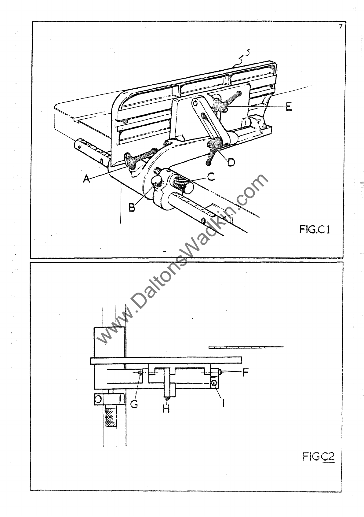
RIVING
The
partment
with
the
well
RIVING
:fit
1.
ing
2.
~"
).
'G'
has
NOTE:TO
the
area
lubricated
The
upright
~it
piece
With
(6mm)
If
and
equal
CLEAR
KNIFE
KNIFE,HOLDER DETAIL
the
jeck
BE~ORE
PLATE:-
riving
ID'
saw
surrounding
riv1ng
knife
'P"
saw
and
overhand
SAW
knife
(fig.
at
a
to
knife
adopting
into
with
in
place
lock
knife
packing
RUNNING, ADJUST
BLADE.
plate
C4A}
set
clearance
the
give
is
the
groov~d
the
lOr:nm
set
firmly
is
not
piece
either
DO
and
radial
free
supplied
f'ollowing
in
in
NOT
is
allows
movement.
oacking
nLJ.ts'G'
knife
place
line
'F'
side
SAW
RUN
situated
the
to
the
slot
in
proceedure:
provided.
to
with
with
out
with
of'
the
GUARD
MACHINE
riving
saw
cut
the
piece
clear
nuts
the
saw
behind
teeth.
in
the
inverted
'E'
around
'G'.
saw,
grub
blade.
TO
GIVE
WIT!iOt!l'
the
knife
plate
-(figC3)
and
saw
partially
screws
MAXIMUM
GUARD
saw
to
rise
It
is
be
position.
bolt
up
teeth
'H'
Lock
IN
in
the
saw
and
fall
important
kept
slacken
until
nuts
PROTECTION
POSITION.
clean
Remove
to
solid
approximatelv
the
'G'
com-
that
and
and
pack-
.
nuts
knif'e
firmly.
AND
IMPORTANT:-
SA\l USED
~
(@@
ENSURE
®
THAT
, H
'(:J\
.-
-
:\1
I H
\
. Riving
Knife
RIVING
KNIFE
BLADE
E
IS
CORRECT
IHICKNl:tSS
FOR
i
)
9
www.DaltonsWadkin.com
www.DaltonsWadkin.com
www.DaltonsWadkin.com
FIGC4 '
FIGC4A
10
www.DaltonsWadkin.com
www.DaltonsWadkin.com
www.DaltonsWadkin.com
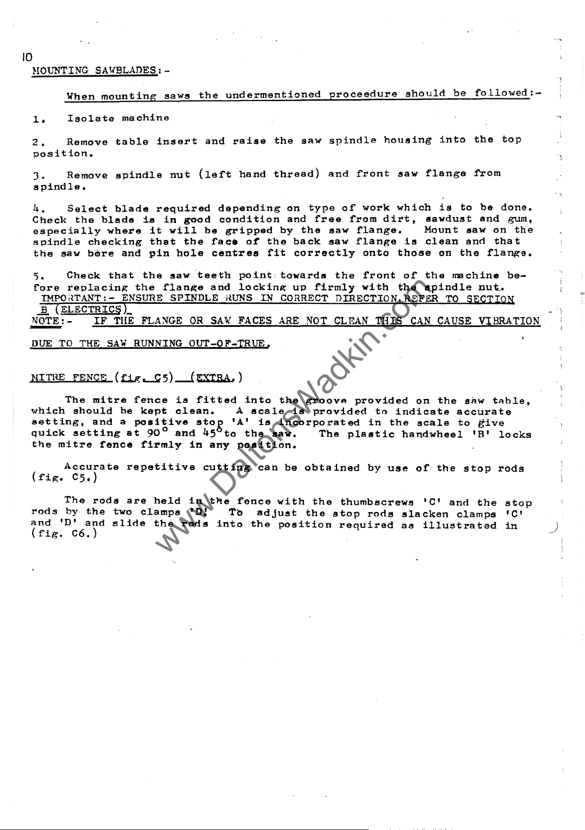
JtIOUNTING SA WBLAnES : -
When
1.
2.
Isolate
Remove
position.
J.
Remove
spindle.
4.
Check
Select
the
especially
spindle
the
saw
'5.
fore
.JL
NOTE:-
DUE
NITHE
Check
replacing
IMPOrtTANT:-
(ELECTRICS
TO
THE
FENCE
mounting
machine
table
spindle
blade
blade
where
checking
bmre
and
that
ENSURE
L
IF
THE FLANGE
SAW
(llg......Q
saws
insert
nut
required
is
in
it
will
that
pin
hole
the
saw
the
flange
SPINDLE
RUNNING
5)
-f
the
undermentioned
and
raise
(left
hand
depending
good
the
condition
be
gripped
face
o£
centres
teeth
OR
OUT-OF-TRUE.
EXTRA, )
and
HUNS
SAW
point:
locking
FACES ARE
the
thread)
by
the
fit
towards
IN
CORRECT
saw
on
type
and
free
the
back
correctly
UP
firmly
NOT
proceedure
spindle
and
front
of
work
from
saw
flange.
saw
flange
onto
the
front
with
DIRECTION,REFER
CLEAN
THIS
should
housing
saw
which
dirt,
is
those
of
the
CAN
be
fol1owed:-
into
flange
is
sawdust
Mount
clean
on
the
spindle
CAUSE VIBRATION
the
from
to
saw
and
the
me
chine
TO
S~CTIQ~
top
be
done.
and
on
that
flange.
be-
nu~.
gum.
-,
the
- I
which
setting,
quick
the
mitre
(:fig.
rods
and
'D'
(:fig.
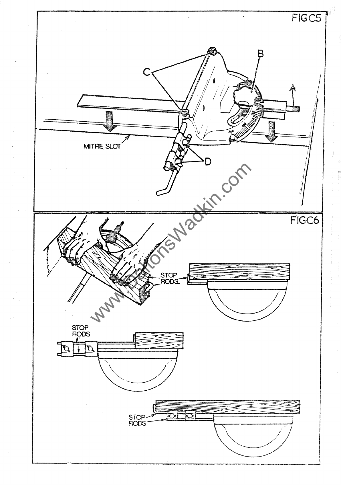
The
mitre
should
and
setting
fence
Accurate
CS.)
The
rods
by
the
and
C6.)
fence
he
kept
a
positive
at
repetitive
are
two
slide
900 and
firmly
held
clamps
the
is
fitted
clean.
stog
in
in
'D!
rods
'A'
45
to
any
cutting
the
Tb
into
into
A
scale
is
the
saw.
position.
can
:fence
adjust
the
the
grOOVA
is
provided
incorporated
The
be
obtained
with
the
the
stop
position
provided
to
indicate
in
the
p1sstic
by
use
thumbscrews
rods
required
on
the
scale
handwhee1
of
the
'C'
and
slacken
as
illustrated
saw
accurate
to
give
'B'
stop
the
clamps
t~blet
locks
rods
stop
'Cl
in
)
FfGCS
www.DaltonsWadkin.com
www.DaltonsWadkin.com
www.DaltonsWadkin.com
11
MITRE
SlOT

12
www.DaltonsWadkin.com
www.DaltonsWadkin.com
www.DaltonsWadkin.com
SAW
PACKING.
It
it
is
out-of-true
and
gap
packing
consequent
The
wood
retains
the
felt
strips
OPPOSITE.
be
amount
duces
at
mouthpiece
underside
in
It
renewed.
Tbe
every
is
usual
not
intended
plate
must
loss
arrangement
the
position.
close
)
should
provision
of
lubricating
heat_and
opportunity,
saws.
is
not
felt
of'
the
and
burning
to
to
be
of
of
packing
the
saw
be
noted
should
provide
that
The
steady
tight
tension
of
a
length
table
At
the
gap
not
of
the
oil,
whilst
the
this
idea
as
the
pieces
and
that
felt
which
felt
a
saw
packing
of
£itting
the
saw,
this
in
the
saw
packings
extending
in
and
to
rear
be
of
provide
af'ter
allowed
inserts
running.
pieces
blAde
will
blade.
place.
the
the
some
not
be
but
beyond
front
a
to
allow
only
are
with
used
packing
it
should
generate
are
Also
of
gap
plate
guide
time,
f'al1
cleans
It
is
lubricated.
some
as
in
the
f'or
application
form
a
guide
pieces
he
heat,
such
depth
wood
the
gap
and
the
the
packings
into
bad
the
theref'ore
of
for
into
noted
resulting
a
way
of
strips
pla
table
saw.
condition.
of
saw,
important
packing,
buckled
the
that
that
the
saw
secured
te
support
similar
(SEE
will
a
small
but
also
but
or
table
the
in
a
a
hard-
teeth
to
the
wood
DIAGRANS
need
to
re-
that,
NOTE;-
REPLACE!oLENT
LENGTHS
OF
FELT
12
x
11
x
100
mm
..
J
I
J

I
www.DaltonsWadkin.com
www.DaltonsWadkin.com
www.DaltonsWadkin.com
I
I
I
I
I~
L_
Saw
~
FIGC
Saw
13
SECTION
AA
Saw
Felt
--..,
I
H~
~~~======~-+~~-:
I
I
-h-'-tH-t_tt)+.~
I
I
Felt--==F=======Cldtl
I
S.,w
t
I
I
I
I
tt11
. I
~arrl
-
-lnOUthpiece
..
.ood
Screw
SECTION
'\
a~
Saw
SECTla~
" ,
/f
j
UI
I
I
I
I
1+
www.DaltonsWadkin.com
www.DaltonsWadkin.com
www.DaltonsWadkin.com
.
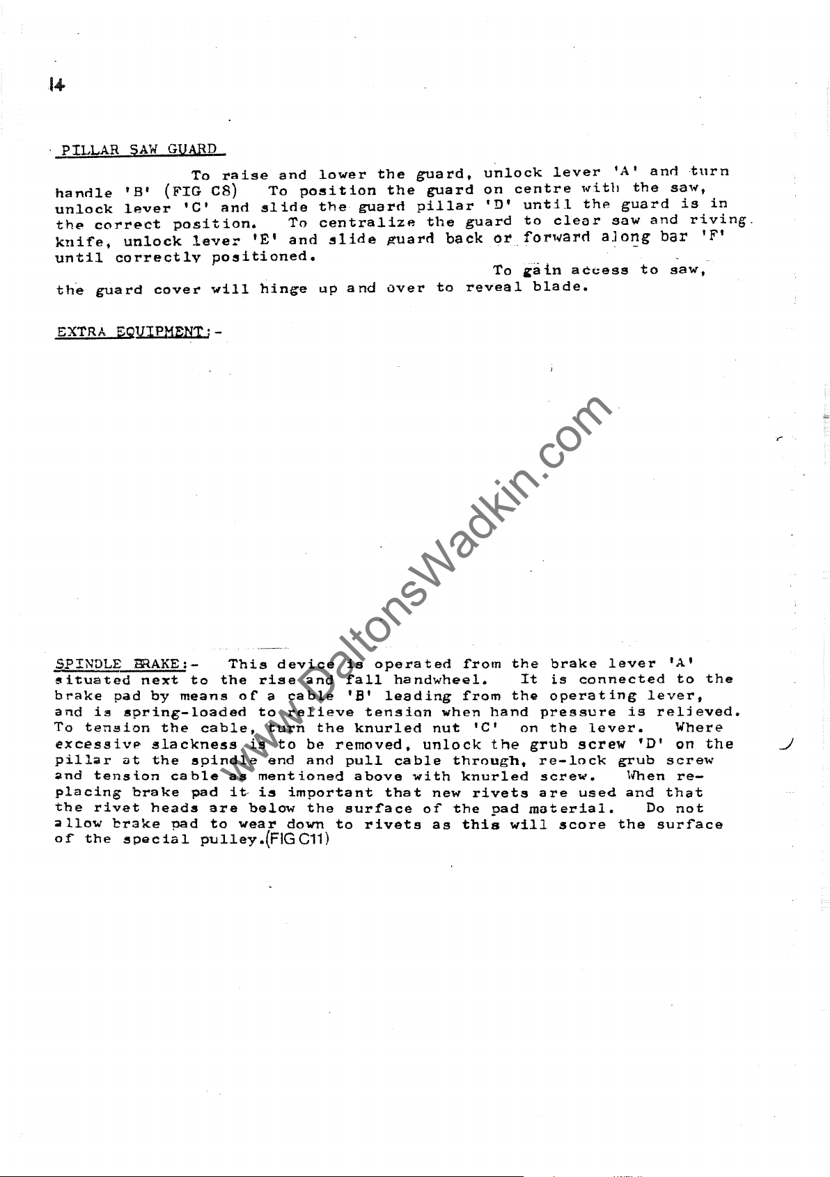
PILLAR
handle
unlock
the
kni"fe,
until
the
SAW
'B'
lever
correct
unlock
correctly
guard
GUARD
(FIG
'Cl
position.
cover
To
raise
CS)
and
lever
positioned.
will
To
slide
'E'
hinge
and
poeition
To
and
lower
the
guard
centralize
slide
up
and
the
the
j!'uarrl
over
guard,
guard
pillar
the
back
to
unlock
on
'D'
guard
or
To
reveal
lever
centre
until
to
clear
fOl"l.,arn
~a{n
blade.
,,,itll
the
aJor:g
access
'A'
guard
saw
anrlturn
the
and
bar
to
sa,,,,
is
riving.
saw,
in
'F'
EXTRA
SPINDLE
situated
brake
and
is
To
ten~ion
excessivp
pill~r
..
nd
tens
placing
the
rivet
allow
of"
the
EQVIPMENTi-
BRAKE
pad
spring-loaded
next
by
the
:-
to
means
cable,
slackness
ut
the
spindle
i.on
cable
brake
brake
:!Special
pad
heads
pad
pulley.(FIGC11)
the
are
to
This
0 f a
is
as
it·
below
wear
device
rise
ca
to
relieve
turn
to
end
ment
ie
important
down
and
ble
the
be
and
ioned
the
is
opera
rall
'B'
leading
tension
knurled
removed,
pull
above
that
surrace
to
rivets
ted
"from
handwheel.
rrom
when
nut
unlock
cable
with
new
or
as
through,
knurled
the
thi~
hand
'Cl
the
rivets
oad
the
It
the
pressure
on
grub
re-lock
screw.
are
material.
will
brake
is
opera t ing
the
lever
connected
lever.
screw
grub
used
score
the
lever
is
'D'
'Yhen
and
Do
lA'
to
the
f
reljeved.
Where
on
the
screw
re-
that
not
surlace

15
www.DaltonsWadkin.com
www.DaltonsWadkin.com
www.DaltonsWadkin.com
FIG
CB
••
38mm
:-:
Rad
FIGCIO
FIG
Cl
I
-
!-~iilli!~-
~------------560mm----------~
B
Rad
38mm
",/
Size of
to suit'sefand
position
saw unit.
cut-out
of
wobble
\
\
16
www.DaltonsWadkin.com
www.DaltonsWadkin.com
www.DaltonsWadkin.com
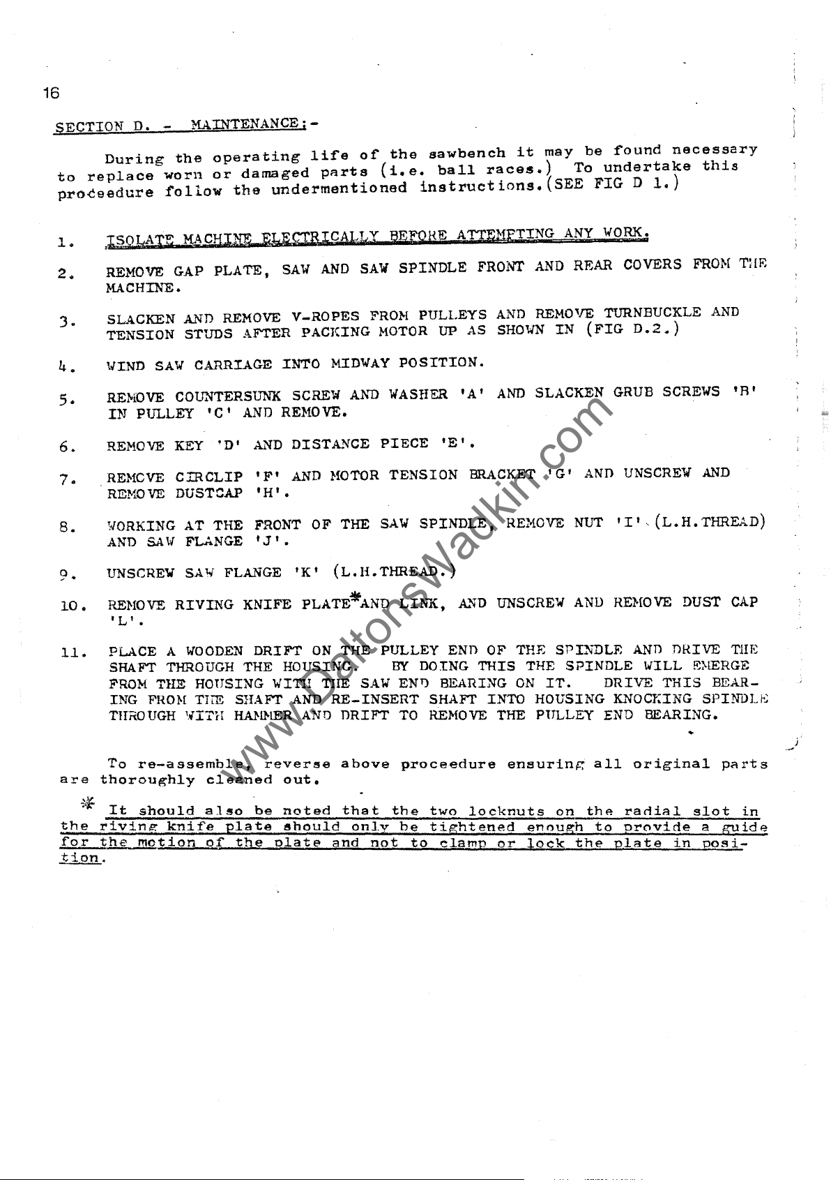
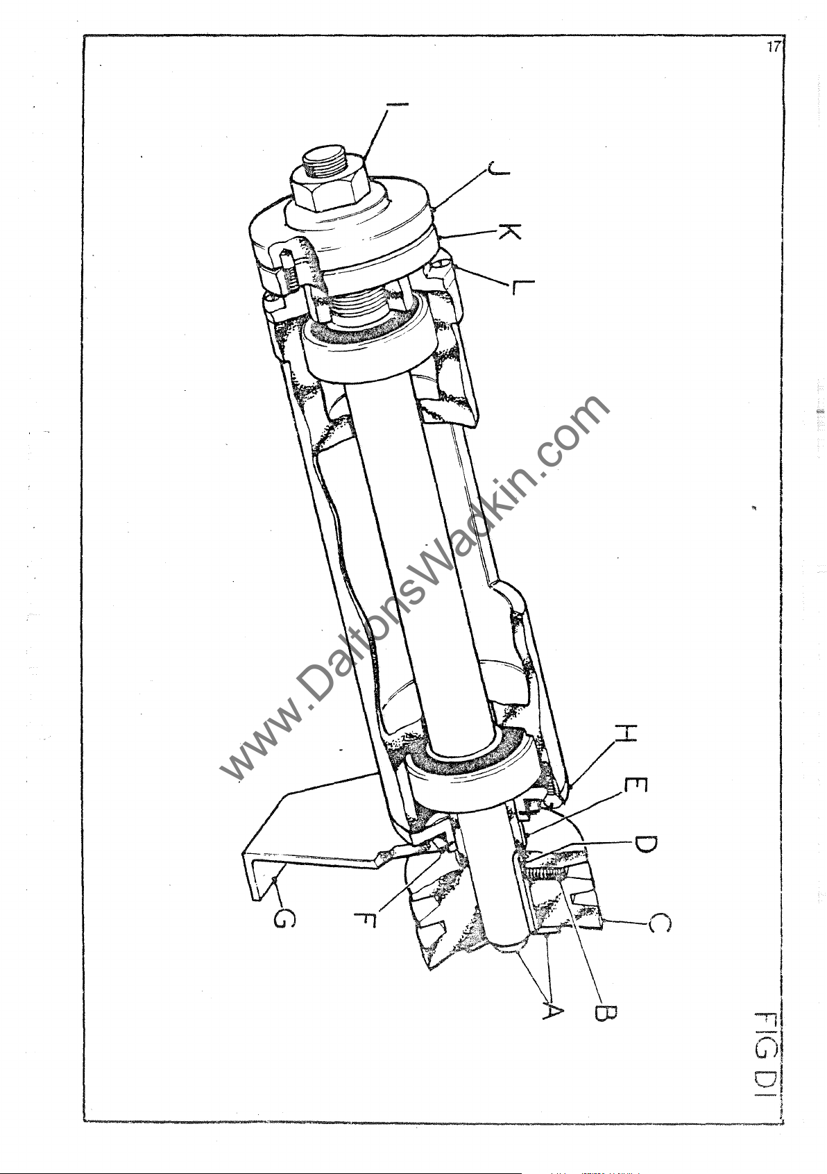
SECTION
During
to
replace
proceedure
1.
2.
,I,§QMIE
REMOVE GAP
MACHINE.
J.
4.
5.
6.
7.
8.
SLACKEN
TENSION
'/IND
REI-lOVE
IN
REMOVE
REHCVE
REMOVE
WORKING
AND
D.
-
MAINTENANCEj-
the
operating
worn
or
follow
MA
CHINE_EJ~IEcrRl.CALLX
AND
STUDS AFTER
SAW
CARRIAGE
COUNTERSUNK SCREW
PULLEY
SA
'C'
KEY
CIRCLIP
DUSTCAP
AT
THE
W FLANGE I J I •
damaged
the
PLATE,
REMOVE
AND
'D'
~~D
'Ft
'H'.
FRONT
life
of
pArts
undermentioned
SAW
AND
SAW
V-ROPES
PACKING
INTO
REMOVE.
DIST~~CE
AND
OF
FROM
MIDWAY
AND
}fOTOR
THE
the
sawbench
(i.
e.
ball
races.)
instructions.
BEFQHE A TTlillW
SPINDLE
PULLEYS
MOTOR
POSITION.
WASHER
PIECE
TENSION
SAW
SP1NDLE.
FRONI'
UP
AS
'A'
'E'.
BRACKET I G I
it
may
be
found
To
undertake
(SEE
NG
AND
AND
REMOVE TURNBUCKLE AND
SHOWN
AND
SLACKEN GRUB SCREWS
REMOVE NUT
FIG D 1.)
ANY
WORK",;
REAR COVERS
IN
(FIG
AND
0.2
UNSCREW
III,(L.H.THREAD)
necessary
this
FROt-{
..
)
AND
Tal':
'R
t
10.
11.
are
'*
the
for
tion.
UNSCREW
RENOVE
'L'
.
PLACE A
SHAFT THROUGH
FROM
ING
THROUGH
To
re-assemble,
SAW
RIVING
WOOD&~
THE HOUSING
FHO:t-[
THE
'HTH
thoroughly
It
should
rivin~
the
motion
also
knife
of'
FLANGE
KNIFE
DRIFT
THE
SHAFT
HANHER AN!)
reverse
cleaned
.
be
plate
the
'Kt
PLATE*AND
ON
HOUSING.
WInl
TIlE
AND
out.
noted
should
elate
(L.B.THREAD.)
LINK,
THE
PULLEY
BY
DOING
SAW
ENT)
RE-INSERT
DRIFT
above
that
on].v
and
TO
proceedure
the
be
not
to
A.~D
UNSCREW
END OF THE
THIS
BEARING
SHAFT
REMOVE
two
INTO
THE PULLEY END
locknuts
tightened
clamp
or
SPINDLE
THE
ON
IT.
HOUSING
ensuring
on
enouLh
lock
AND
REHOVE DUST
SPINDLE
DRIVE
KNOCJ=ING
all
th~
to
the
plate
AND
WILL
THIS
BEARING.
original
radial
provide
CAP
DRIVE
TIlE
~~~RGE
BEAR-
SPINI)Li~
parts
slot
a
gyide
in
posi-
in
-
www.DaltonsWadkin.com
www.DaltonsWadkin.com
www.DaltonsWadkin.com
o
'--t)

18
www.DaltonsWadkin.com
www.DaltonsWadkin.com
www.DaltonsWadkin.com
BELT
saw
maximum
correct
the
tioned
distance
the
of
applying
tion
def'lection.)
REPLACING
buckle
,,.,arde
POINTS
TENSION:-
On
spindle
"running
proceedure.
By
belts.
the
~ulley3
is
To
and
retension
TO
the
standarn
is
by
means
e~ficiency
belt
tension
in"
turning
of
a
force
not
BELTS,.:-
replace
thus
NOTE
turnbuckle
the
pulleys
To
achieve
(FIG
greater
belts,
relieving
as
WHEN
at
machine
of
and
life.of
is
maintained
period.
(SEE
given
HAINTAINING BELT
D3.)
right
than
FIG.
can
the
and
0-5mm
decrease
above.
the
three
~n~Jes
To
D.2.)
'A'
be
correct
adjust
ALPHA
these
linking
increased
per25mrrrof
tension
drive
tension
ar.~
pulley
at
tension,
with
on
the
DRIVES:-
from
500
type
belts,
all
the
the
to
the
central
centre
belts
the
it
times
belts
tension
provide
measure
turnbuckle
Along
span
5.
SHP
"V"
Belts.
is
important
~rom
follow
-
(e.g.584·
distance
for
their
motor
new,
studs,
greater
the
the
especially
the
the
centre
until,
belt,
span:::
by
screwing
removal.
(4KW')
To
ensure
that
undermen-
centre
tension
whilst
the
to
the
the
in
on
distance
deflec-
Tl-5mm
turn-
After-
1.
.2.
J.
4.
5.
6.
ALWAYS
REPLACE
ALl-lAYS
ENSURE
DO
IMPLEM~NTS
ENsrJ!1E PULLEY
RUST
NOT
OR
MAINTAIN
WOHN
REPLACE
pm
.LEYS
PRISE
AS
BURRS
CORRECT
m'::LTS
WORN
ARE
BELTS
THIS
GROOV'ES
'mIcn
WITH
OR
CO
RH.ECTL
OVER
CAN
AND
ARE
BELT TENSION •
SAME
D.\J.tAGED
PULLEYS lfITH SCREli DRIVERS
DAMAGE
PRESENT.
TYPE AS
BELTS DtMEDIATELY.
Y ALIG!\ED.
BELTS.
BELTS
ARE
SPECIFIED.
CLEAN
AND
RE}10VE
OR
OTHER
k"fY
OIL,
SHARP
GREASE
j

u---+--t---A
www.DaltonsWadkin.com
www.DaltonsWadkin.com
www.DaltonsWadkin.com
19
Method
motbr
tension screws
outlined in section
of
packing up
for remcNal of
as
D1
I
FIG
FIG
DEElnECTION
__
O·5rnm
OF
PE R 25
SPAN
mm
D2
D3
__
.

20
www.DaltonsWadkin.com
www.DaltonsWadkin.com
www.DaltonsWadkin.com
SA~
MAINTENANCE:-
Effici8nt op6rat1on of a
the
say
of
the
spindle.
to
ensure
BANGING;-
'Ranging
fourth
sive
whilst
teeth
SAW
in
square
equal
gu11At
rounded.
~ve18
their
original
machine.
or
block
running.
riled
SRARPENING:-
Do
a
vice
faces
number
of
as
original
spindle,
straight
down'
rifth
in a wooden
lightly
not
run
as
shown
are
of
the
saw
With
in
{FIG.
profile,
and
sharpening.
a
required
strokes
crosI!
the
The
cutting.
should
The
to
saw
in
in
the
D7.)
shape
it
and
is
saw
saw
must
be
holder
eaw
should
remove
when
(FIG
with
same
cut
saws
In
the
necessary
flanges
done
blunt.
D5.)
(FIG
a
the
gullets
circular
being
also
To
(FIG
the
D6.)
flat
manner,
points
run
on a new
range
04.)
then
ranging
To
With
file.
course
become
to
grind
saw
depends
perfectly
at
the
saw
down,
lightly
be
removed
marks.
re-sharpen
rip
saw
Sharpen
taking
are
needed
01
repeated
the
correct
or
feed
against
and
teeth,
hy
giving
At
the
care
with
shallow.
ssw
on
true
square
any
Baw
a
square-edged
the
by
hand,
chisel
same
to
keep
back
filing,
To
on a saw-sharpening.
running
to
peripheral
after
the
saw
tops
holo
edges
each
time,
tooth
the
and
saws
restore
the
the
teeth
of
the
file
gullet
front
of
axis
speed
abra-
the
saw
and
an
the
well
lose
the
SETTING:-
The
body
set I (Le.)
in
side
a
seen
being
in
indicetes
that
&
so
(FIG
or
piece
in
cut,
We
(FIG
For
the
D12.)
amount
there
D8)
else
er
timber
(FIG.
but
can
DlO)
the
hand
nnmber
32
ml1l Bore
is
the
teeth
For
the
D9)
is
supply
This
amount
setting,
or
01
set
~reedom
are
good
saw
will
where
The
uaua1ly,
a
small
device
o~
saws
should
from
bent
sawing.
run
the
aMount
machine
will
set
small
used
be
sufficient
~riction.
alternately
this
to
one
result
by
devices
does
should
of
SAt.
for
accept
micrometer
not
amount
side.
varies
.3mm-.4mm.
precisely
saws
can
warrant
to
give
Saw
teeth
to
the
or
set
To
check
be a small,
according
up
to
dial.
be
supplied
a
machine
clearance
are
right
should
setting
36"
where
generally
or
the
even
to
in
diameter,
(SgE
left
be
equal
set,
triangle,
the
saws
it
to
the
'spring
as·
at
cut
timber
as
shown
and
is
felt
FIGs.Dl1
saw
shown
each
into
as
STANDARD SAW AND
PIN
HOLE
CENTRES
r
I
-.:s
-5
CNT
mm

-----
www.DaltonsWadkin.com
www.DaltonsWadkin.com
www.DaltonsWadkin.com
-_._----
21
FIG
FIGD6
Area of tooth
~.
FIG
D4
__
-----------
Clearance
angle15°
,br.,
:aw ' cu:net
set-over
shown shaded ---....... ..
<:it:
08
Top
a gle10
RIP
SAW
4~
bevel
0
saw
FIGD7
FIG
09
Clearance
angle
43°
CROSSCUT
SAW
FIG
FIG
DIO
IG
011
Dl2
10
15
",.
20

FIG DI3
www.DaltonsWadkin.com
www.DaltonsWadkin.com
www.DaltonsWadkin.com
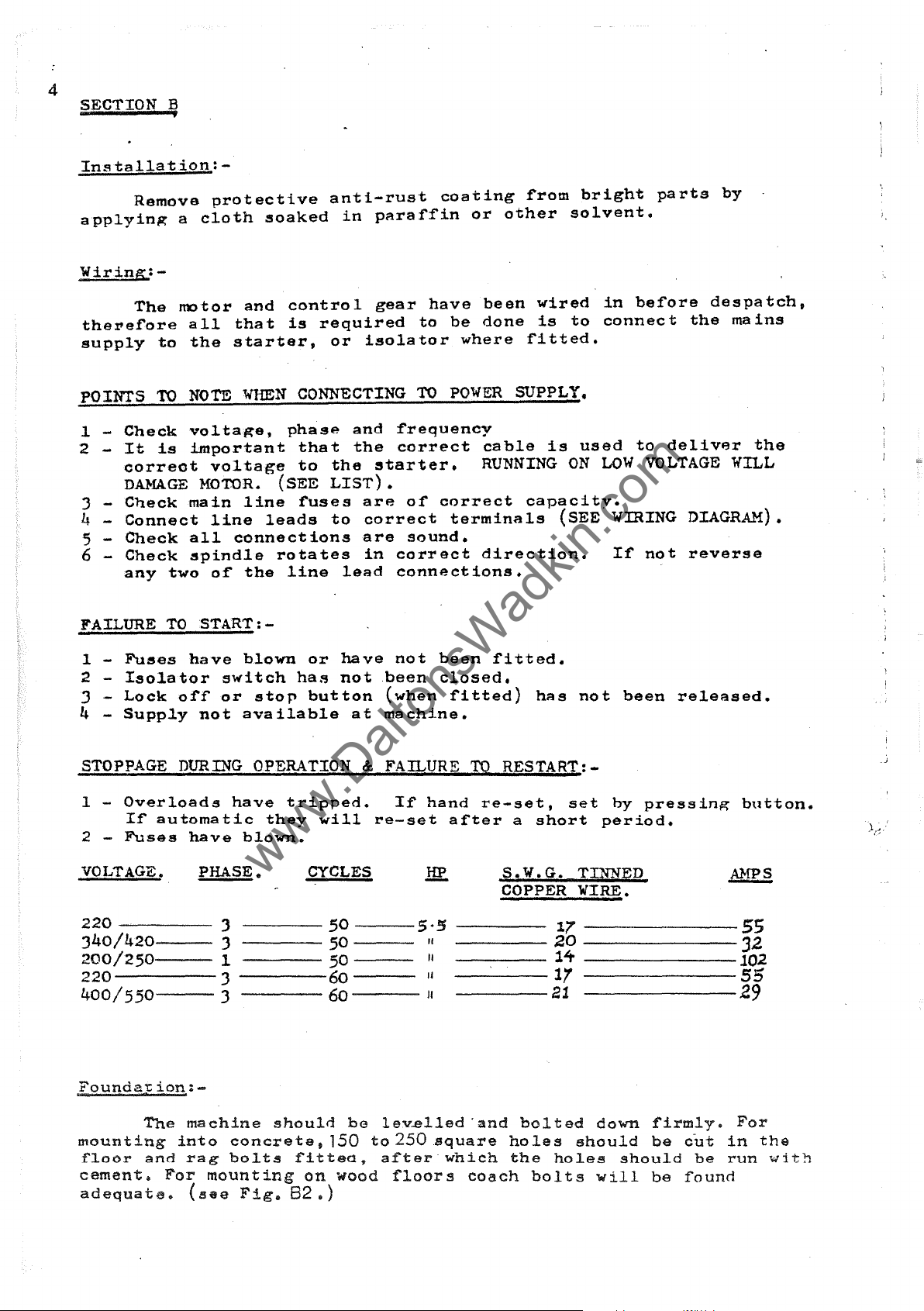
LUBRICATION
A - Oil and clean weekly.
DIAGRAM
~
_---r-
-~
- i
/)/
~J
4~_~
. I
\
/),
U/"
-'--
/ "
\ J
"'~-.
I
t--
\
I
~.."
'\-t-
L\.,,@
\
\
-=-=
".,
'}
\J::I
B-Oil
C-"THRUST
D-Grease-two
weekly'
each
end
r
DLJst
Outlet
230x1l5.
RACE:'
shots
per
year.
oil weekly.
A
A
" "'-D
.......
Lt
'"
.,/
~
\-..
300.

23
www.DaltonsWadkin.com
www.DaltonsWadkin.com
www.DaltonsWadkin.com
.--
S
SPARE
eTION
PARTS
11
LISTS
11
E

24
www.DaltonsWadkin.com
www.DaltonsWadkin.com
www.DaltonsWadkin.com
REF.
NO-:-
1
2
3
4
5
6
7
(8
(
9
10
11
12
13
14
15
16
17
20
21
22
23
25
26
27
28
29
30
PART
NO.
BSW
BSW
BSW
BSX
BSW
BSW
BSW
PLEASE
BZG
MAIN
NO.
OFF
1
2
3
12
11
137
27
STATE
70
VOLTAGE,
BASE
1
1
1
2
1
1
1
PF..ASE & FREQUENCY
1
2
2
8
4
4
2
2
4
8
2
2
)
2
2
2
1
2
3
2
ASSEMBLY
DESCRIPTION
BASE
HAIN
TABLE
GAP
SPINDLE
BASE
FRONT
BASE
BROOK
WADKIN
REAR
FRONT
No.IQ
M12 x
1 2
10
M8 x 15
MIO x 35
MIO x 25
M6 x ]0
6
SPRING
M6
WING
I
()
M8 x 15
1/8"
2BA x
DRlVEPINS
(STANDARD)
PLATE
FEET
COVER
COVER
RT
BURSGREEN
WOOD
WOOD
WOODSCREWS
30
mm
WASHERS
mm
DIA
mm
WASHERS
GUARD
NUTS
NUT
mm
EXTER..l\lAL
DIA
20
PULLEY
3 STARTERl
SAW P ACKINGS
mm
x
mm
mm
mm
mm
mm
BRASS
mm
COVER
SA\{ P ACKINGS
LONG
25
mm
LONG
ROUND
LONG
LONG
LONG
HEXAGON
CLIP
CIRCLIP
LONG
ROUND
RIVETS
LONG
1
N.M1EPLATE
HEXAGON
LONG
DOWELS
HEAD
SCRE~-1S
HEXAGON
HEAD
SCRE1TS
BOLTS
SCREw"S
BOLTS
BOLTS
SCREWS
"mEN
ORDERING
SP
A.1lli
PARTS
PLEASE
QUOTE P ,,\RT
N1JM:BER
k'l:D
SERIAL
NlJMBER
OF
HACHINE
4
www.DaltonsWadkin.com
www.DaltonsWadkin.com
www.DaltonsWadkin.com
1
1
1
1
1
1
1
1
1
1
1
1
1
1
1
1
1
1
1
1
1
1
1
1
1
1
\7
6
\
5
26
www.DaltonsWadkin.com
www.DaltonsWadkin.com
www.DaltonsWadkin.com
REF
NO.
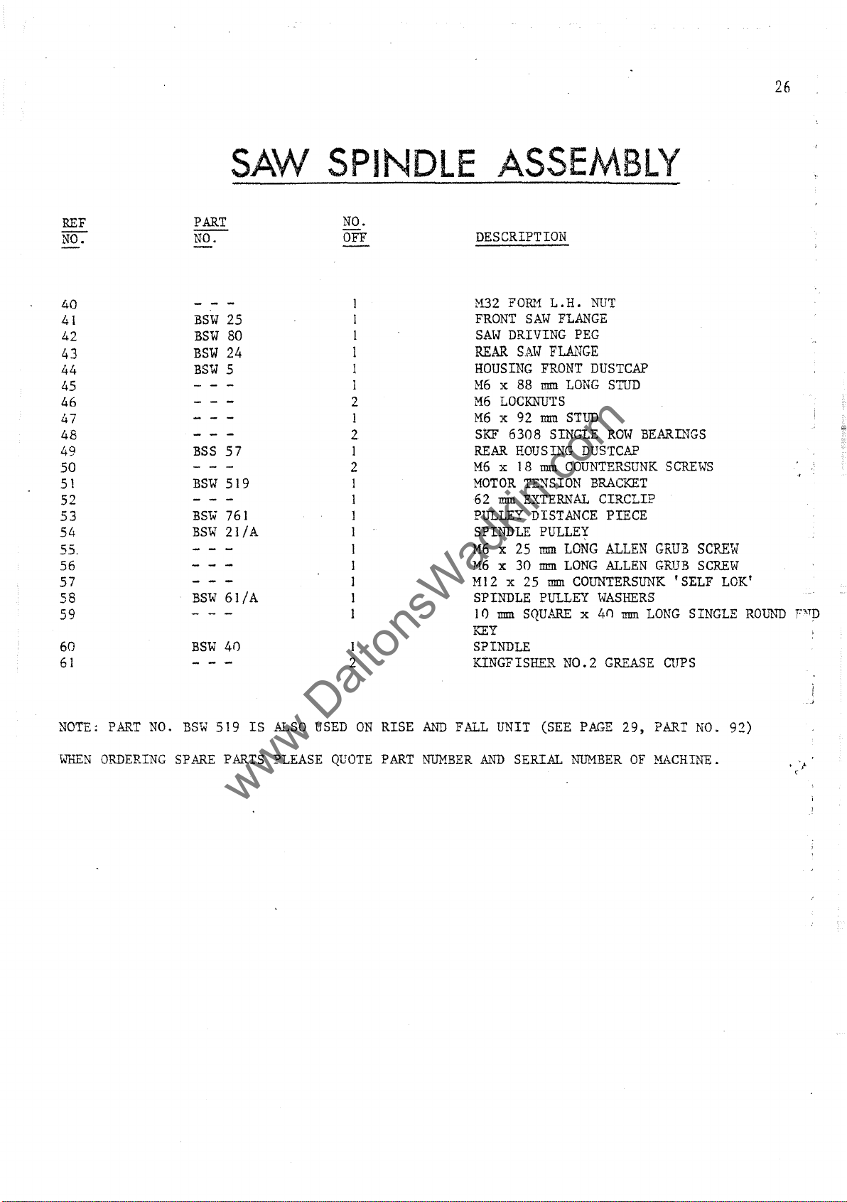
40
41
42
43
44
45
46
47
48
49
50
51
52
53
54
c;-
-
-'-
56
57
58
59
60
61
SAW
PART
NO.
BSW
25
BSW
80
BSW
24
BSW
5
BSS
57
BSW
519
BS"W
761
BSW
21
lA
BSW
61
lA
BSW
40 1
SPINDLE
NO.
OFF
I
I
1
1
1
1
2
1
2
1
2
1
1
1
1
1
I
1
1
1
2
DESCRIPTION
M32
FRONT
SAW
REAR
HOUSING
H6
M6
M6 x 92
SKF
REAR
M6 x 18
MOTOR
62
PULLEY
SPINDLE
M6
M6 x 30
M12 x 25
SPINDLE
10
KEY
SPINDLE
KINGFISHER
ASSEMBLY
FORM
L.H.
NUT
SAW
FLANGE
DRIVING
S.,l\.W
x:
88
LOCKNUTS
6308
HOUSllTG
TE~SION
rrnn
EXTERNAL
x:
25
rrnn
SQUARE
PEG
FL.AJ.'~GE
FRONT
rrnn
rrnn
rrnn
DISTANCE
PULLEY
rrnn
ID.!ll
rrnn
PULLEY
DUSTCAP
LONG
SINGLE
COUNTERSUNK
LONG
LONG
NO.2
STUD
STun
Rmol
DUSTCAP
BRACKET
CIRCLIP
PIECE
ALLEN
ALLEN
COUNTERSUNK
i.J'ASHERS
x
4n
rrnn
GREASE
BEARllTGS
SCREWS
GRUB
GRUB
'SELF
LONG
SINGLE
CUPS
SCREW
SCREW
LOK'
ROv~~
F1ITD
NOTE:
wOEN
PART
NO.
ORDERING
BSW
SPARE
519 IS
PARTS
ALSO
USED
PLEASE
ON
QUOTE
RISE
PART
AND
FALL
NUMBER
UNIT
AND
(SEE
SERIAL
PAGE
NUMBER
29,
PART
OF
MACHINE.
NO.
92)

42
www.DaltonsWadkin.com
www.DaltonsWadkin.com
www.DaltonsWadkin.com
43
---------------------------------------------
44 45 46 49
ET<'\
mIPillDmUIIlllJmmmmIDllJl)JDl)J
o
',:::':;';<>'
'j
,
...
~Ullml!!lmnlllilllrlllmmmll!l)
6~
47 46
@
:
@/J
59
6/
::.J-SI
B
,
CC
60
-----7.,..-
.:
;
,,-\
SAW
www.DaltonsWadkin.com
www.DaltonsWadkin.com
www.DaltonsWadkin.com
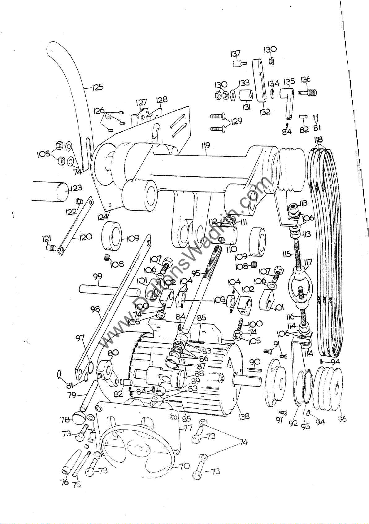
RISE
&
FALL
ASSEMBLY
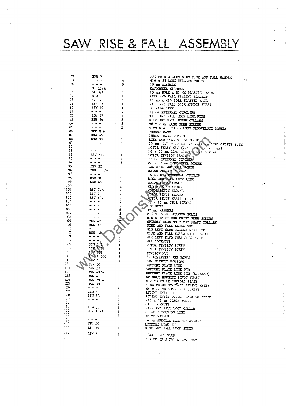
86
87
a8
89
90
91
92
93
94
95
96
91
98
99
100
101
102
103
104
105
106
107
108
109
110
11
112
: 13
ll~
!
15
i 16
117
lIB
119
120
121
122
;23
124
125
126
127
122
130
131
i32
!3~
!34
:35
136
Di
138
77
78
79
80
81
82
83
84
85
t
70
73
74
75
76
BSW
S
6698/A
asw
5296/3
BS""
BS""
SSW
asw
SKF
BSW
BSt;!
SS""
BSW
SS::
S$''/ 36
5SW
BSW
BS'W'
SSW
SS""
BSW'
SSW
BSW
asw
asw
ALPHA
SSW
BSW
BSW
SS"
BS
..
SSW
aSW)O
BS"
BS" 53
BS~
5S;; J
BSi!
:0
BSW
39
125/
37
34
0.6
46
33
519
32
Ill/A
43
7/A
7
134
42
31
124
142
147
135
4
SO
51
49(A
41
29/A
54
38
8/A
9
10
35
19
500
I
4
A
9
1
1
4
2
2
3
2
1
J
3
I
1
2
1
1
1
1
1
2
2
2
2
4
3
6
2
2
2
I
J
1
2
2
3
4
I
I
2
3
225
mm
DrA Attr.nNIUM !USE
'HO x 35
10
ElANDWIl'.EIL
1 0 """
RISE A
40
RISE
LOo:::mG
12
RL"E
RISE
M6
5
mm
ntRUST
ntRUST
RISE
20
HOTOR
M6 x 20
XOTOR
62 = L{
M8 x
SAW
XOTOIt
J 6
RISE
MOTOR
M]O x 35
MOTOR
MOTOR
MOTOR
!{8
:,
MI0
] 2
mm
LONG
mm
WASHERS
SP
INDLE
BORE
x 80
..
'\'D
FALL
J!ll!J
x
MJ 0 BORE
AND
FALL
LINK
mm
EXTERNAL CIRCLIPS
A.'ID
FALL
AND
FALL
x 6
mm
LONG
DU x 30
RACE
RACE
SHROUD
AND
FALL
mm
VD
le 22
5aAFT
KEY
mm
LONG
RISE
!!ll.11
NUTS
30
AND
lOam
TENSION
PULlEf
DU
PIVOT
PIVOT
PIVOT
PIVOT
IlASI!:EllS
•
.:.R..'<AL
mm
LONG
AND
n:nR.'.iJ..
;;
ALL
l1M
GRUB
BRACKET
FALL
7.5
LOCK
SHAFT
StuDS
BLOCKS
BLOCKS
SHA.."T
HEUGCN
MM
B1U.RING
LOCK.
f..nCK
SCREW
GRUH
mm
LOt;'G
SCRnT PIVOT
mm
(7. 5 HP
COfJN'!ERSIDl1C
crr-CLIP
GRUB
liP
SCREW
M12 x 25 ~ HEXAGON
MI0
le
12
mm
DOG
SPINDLE
RISE
M20
RISE
M12
M 1 2
MOTOR
MCTOX
1'ZNS
'SFACESAVER'
SAl.'
SUP?OR'!
SUPPOR:"
SUPPORT
SPINDLE
RIVING KNIFE SUPPOR':
4 = THICK
M6
R..:.--VING
ltIVING KNIFE
!flO
Ml6
RISE
SPL'IDLE
16 ~ I;ASHER
16
LOCK.!!IG
L:~l:K
7.5
AND
LEn
AND
LEFT
LOCK:NtJ'!S
TENSION
n~SION
ION
SPINDLE
x
12
KNIFE
le 45 =
LOClQIUTS
A.'m
:mn
S?ECIAL
LL'IK
? 1
VO:'
HP
lS.5
HOUSING
:"UT
PLATE
PLArE
PLATE
HOUSING
mm
FALL
HOUSING
PaTh'"!'
PIVOT
FALL
SCReW
!UND
TE:REA!l
'!!
ALL
Scru:-w
RAND
TIll'-1':AD
SCP.EW
SCREe
vu:
ROPES
ROUSING
tTh1<
LnlK
LINK
PIVOT
STMtiiARD
LONG
GRUB
EOLDER
HOLDER
COACH
LOCK
L~nc
S-;"OT:tJ) ;;'ASi1ER
~:UT
S:::WD
i(';lL
D1J2S
..
BOLTS
Alm
BOLTS
PLASTIC
PLASTIC
HANDLE:
LINK.
COLLARS
SCREWS
OiD x
SCREW
CIRCLIP
LINK
CC!.LAR5
BOLtS
:m'!
LOCK
LOCK
tOcnroTS
PIN
pm
PLAn:
R..:.--VL'fG
SCREWS
PAo:::mG l'!:ECE
COLLAR
FRA..'iE
P.A!TDLE
BRACKET
BAll
stIA.:'"'1'
PINS
GROOVELOC:r
22
U1
n:m
SCl'.EYS
GRUB
SCR..."1oIS
SRAFT
COLL.l.RS
NUT
COLLAR
(KNURUDl
SHAFT
KNITE
FALL
DOWELS
IllIII
LONG
x 8
=1
SCRl!:101S
!1.A.lDLE
OTL:I:'!E
28
BUSH
, r
, ,
\25
www.DaltonsWadkin.com
www.DaltonsWadkin.com
www.DaltonsWadkin.com
1
1
1
1
1
1
1
1
1
1
1
1
1
1
1
1
1
~
1
1
1
1
1
1
1
1
30
www.DaltonsWadkin.com
www.DaltonsWadkin.com
www.DaltonsWadkin.com
CANTING
REF
NO.
160
161
162
163
164
165
166
167
168
169
170
171 1 M8 x 12
PART
Ne:"""
BSW
15
BSW
8
BSW
14
BSW
83
BSW
66
BSW
65 I
172
173
174
175
176
BSW
BSW
16
17
177
178
179
180
181
182
183
184
185
186
187
188
189
190
191
BSW
57/A
BSW
r23
BSW
58
BSW
526
BSW
63
BSW
57
BSW
12
BSW
56
BSW
139 1
NO.
OFF
1
3
1
1
1
1
1
1
3
1
I
1
1
1
1
1
1
1
1
1
2
fENCE
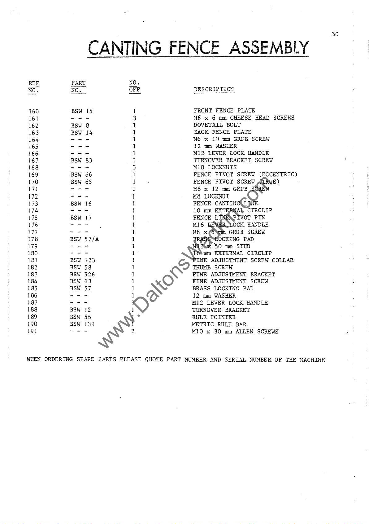
DESCRIPTION
FRONT
'116
x 6
DOVETAil.
BACK
FENCE
M6
x J n
1 2
mm
MJ
2
LEVER
TURNOVER
MIO
LOCKNUTS
FENCE
FENCE
M8
LOCKNUT
FENCE
10
:mm
FENCE
MI6
LEVER.
M6
x 6
BRASS
MJ2 x 50
mm
] 6
FINE
ADJUSTMENT
THlJ}fB
FINE
ADJUSTMENT
FINE
ADJUSTMENT
BRASS
12
mm
M12
LEVER
TURNOVER
Rt"LE
POINTER
METRIC
MJ
0 x
ASSEMBLY
FENCE
mm
WASHER
PIVOT
PIVOT
CANTING
EXTER..,,{AL
LINK PIVOT
mm
LOCKING
EXTER.1IiAL
SCREiv
LOCKING
WASHER
RlJLE
30
PLATE
CHEESE
BOLT
PLATE
mm
GRUB.
SCREW
LOCK
HANDLE
Br~~CKET
SCREW
SCREW
mm
GRUB
SCREW
LINK
ClRCLIP
LOCK
HANDLE
GRUB
SCREW
PAD
mm
STUD
CIRCLlP
SCREW
BRACKET
SCRE1<l
PAD
LOCK
HANDLE
BRACKET
BAR
mm
ALLEN
SCREWS
HEAD
SCREW
(ECCENTRIC).
(TRlJ"E)
PIN
COLLAR
SCR-VWS
,
WHEN
DRDERING
SPARE
PARTS
PLEASE
QUOTE
PART
NUMB.ER
AND
SERIAL
NlJMBER
OF
THE
}~CHINE

160
www.DaltonsWadkin.com
www.DaltonsWadkin.com
www.DaltonsWadkin.com
31
191--/
PILLAR
www.DaltonsWadkin.com
www.DaltonsWadkin.com
www.DaltonsWadkin.com
GUARD
ASSEMBLY
"
3
"
REF.
ND.
200
201
202
203
204
205
206
207
212
213
214
215
216
217
218
219
220
221
222
223
224
225
226
227
228
229
230
231
232
233
PART
NO:-
BSW
79
STOCK
BSW
57
BSW
73
BSW
72
BSW
71
BSW
12]
BSW
82
BSW
69
BSW
70
S12S/A
6698/A
BSW
77
BSW
76
BSW
68
BSW
75
BSW
67
BSW
7S/A
NO.
OFF
3
J
2
J
1
1
1
]
J
]
1
I
3
3
1
I
1
1
1
1
I
1
1
1
I
1
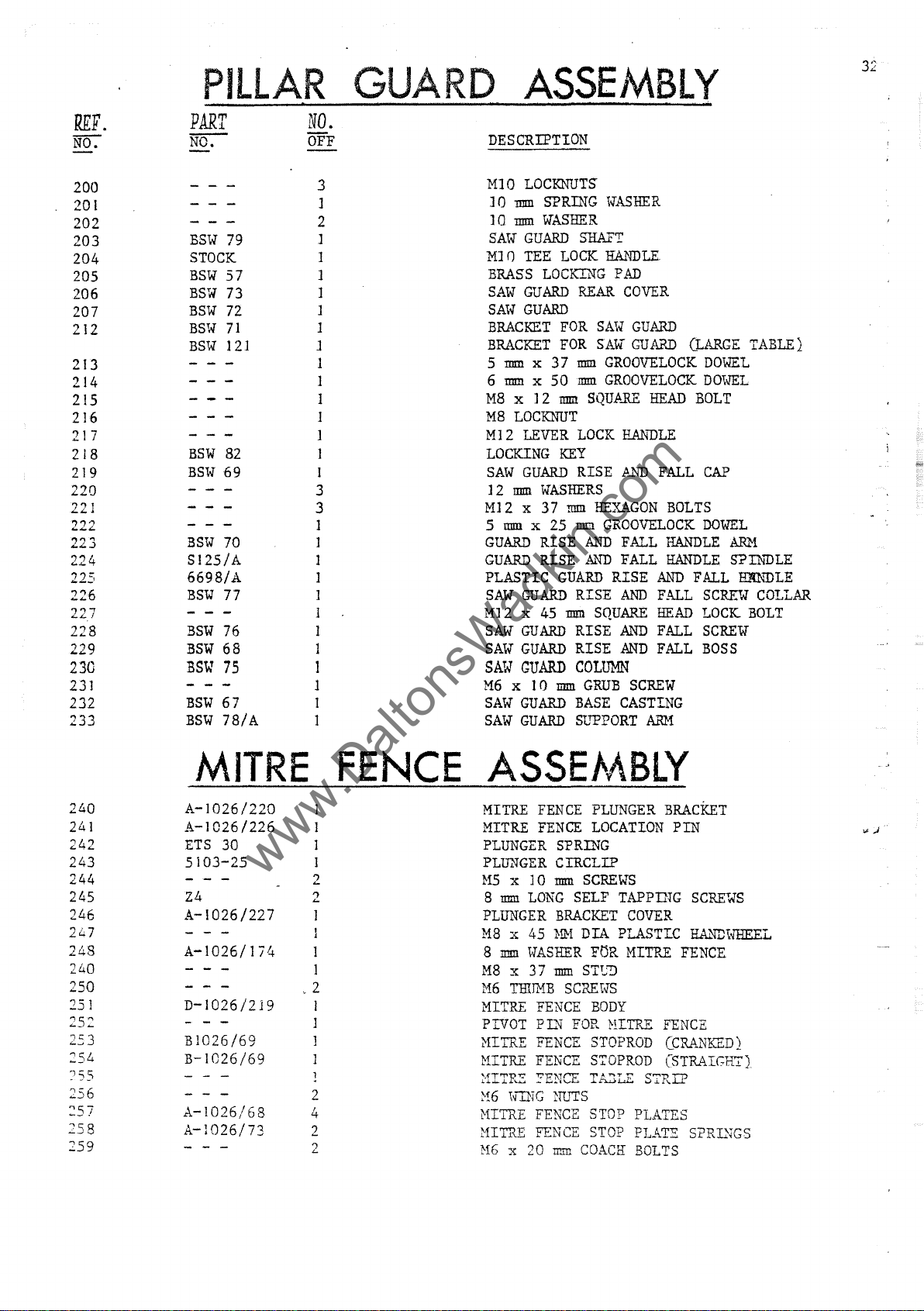
DESCRIPTION
MIO
LOCKNUTS
] 0
mm
SPRING
1 0
1IIID.
WASEER
SAW
GUARD
MI
()
TEE
LOCK
BRASS
SAW
SA~{
BRACKET
BRACKET
5
6
M8
MS
M] 2 LEVER
LOCKING
SAW
] 2
M12 x 37
5
GUARD
GUARD
PLASTIC
SAW
M12 x 45
SAW
SAW
SAW
M6
SAW
SAW
LOCKING
GUARD
GUARD
mm
x 37
mm
x
50
x ] 2
LOCKNUT
GUARD
mm
WASHERS
mm
x 25
RISE
RISE
GUARD
GUARD
GUARD
GUARD
x 1
()
GUARD
GUARD
FOR
FOR
mm
KEY
mm
GUARD
mm
mm
WASHER
SHAFT
HANDLE
PAD
REAR
COVER
SAW
GUARD
SAW
GUARD
mm
GROOVELOCK
mm
GROOVELOCK
SQUARE
LOCK
H.Mil)LE
RISE
)..Nl)
HEXAGON
mm
GROOVELOCK
k~
FALL
AI.'ID
FALL
RISE
RISE
AND
SQUARE
RISE
AND
RISE
AND
COLUMN
GRUB
BASE
SLTPORT
SCREW
CASTING
ARM
HEAD
FALL
BOLTS
HANDLE
HANDLE
AND
FALL
HEAD
FALL
FALL
(LARGE
DOWEL
DOiJEL
BOLT
CAP
DOWEL
ARM
SPTh'DLE
FALL
SCREW
LOCK
SCREW
BOSS
TABLE}
HKNDLE
COLLAR
BOLT
240
241
242
243
244
245
246
247
243
240
250
251
252
2.5
254
'55
256
257
258
259
MITRE
A-I026/220
A-I026/226
ETS
30
5103-25
Z4 2
A-I026/227
A-1026/174
D-I026/219
3
B1026/69
B-I026/69
A-I026/68
A-1026/73
FENCE
2
1
I
I
I
> 2
1
J
2
4
2
2
ASSE/v\BlY
MITRE
MITRE
PLUNGER
PLUNGER
M5
8
PLUNGER
MS
S
MS
H6
MITRE
PIVOT
~fITRE
MITRE
i'fITP~
~6
MITRE
MITRE
H6
FENCE
FENCE
x 1 0
mm
LONG
x
45
mm
IvASHER
x 37
THUMB
FENCE
PDI
FENCE
FENCE
::ENCE T&3LE
\{ING
FENCE
FENCE
x 20 1I!Ill
PLUNGER
LOCATION
SPRING
CIRCLIP
mm
SCREWS
SELF TAPpmG
BRACKET
HM
mm
SCREIV'S
FOR
NUTS
COACH
COVER
DIA
PLASTIC
FOR
MITRE
STT..::J
BODY
HITRE
STOPROD
STOPROD
STOP
STOP
PLATES
HAT::::
BRACKET
PIN
FENCE
FENCE
(CRANKED}
(STRAIGHT)
S7RIP
BOLTS
SCREWS
RAl.'ID1:{HEEL
SPRTI~GS

33
www.DaltonsWadkin.com
www.DaltonsWadkin.com
www.DaltonsWadkin.com
221
220
215 216
214~~
2f2---::-2_
/~~\
.
131
_-;-=-·
--
. • G
.'
-..--
~
\'
207
233 0
i
206
217-?
cr---_
\"1\
204
205
222 223
219____
218.
~
~
re
225~
224~U
,
~.
!
.,
~5
9 '
226
~
I
222
2b;~>JJ
202
201
229
200
230
227
228
;
..
246
247-9
245
~!~~
--""'.
248-© i\lto--250
249-D
242~
j.
241
240
~---~-_6:~~~~====~
.
251
232
~
256
257
258
259
255
I
-
_"
231
253;
254
256 258
~-259
257

34
www.DaltonsWadkin.com
www.DaltonsWadkin.com
www.DaltonsWadkin.com
SPINDLE
REF
NO.
290
291
292
293
294
295
<;,296
297
298
299
300
301
302
303
304
305
306
307
308
309 1
310
311
312
J.>-313
PAR:1:
NO.
/ "
:;~f~
ro-;v2l
BSW
131
BSW
148
BSW
145 1
BSW
132
BSW
129
107.PA
BSW
BSW
BSW
7/8
128
125
133
RH
NO.
OFF
1
1
2
]
]
]
1
]
2
2
1
1
1
I
1
1
]
I
"2
BRAKE
PESCRIPTION
20"
BSW
BRAKE
BRAKE POST
MS
LOCKNUTS
]2
mm
WASHER
MJ2
NUT
M6 x ] 0
BRAKE
46
mm
P
AD
M6
MS
MS
22
nnn
BUSH
BRAKE
BRAKE
BRAKE
BRAKE
x
M8
SPECIAL SPINDLE PULLEY
M8 x ] 6
M6 x 50
3
nnn
BRAKE
BRAKE
mm
STOP
BRAKE
ALIGNMENT SPRING
LOCKNUTS
LOCKNUTS
SPECIAL
DID
ARM
PIVOT
LEVER COMPLETE
LEVER
12
mm
mm
mm
DrA
COPPER
LINING
PAD
ASSEMBLY
CABLE
GRUB
SCREW
SCREW
RETURN
WASHER
x
10
PL~
ARM
GRUB
GRUB
COUNTERSUNK
FOR
BACKPLATE
mm
I/D
SCREW
SCREW
RIVETS
20"
SPRING
x ] 2
FOR
SCREW
BSW
mm
LONG
BRAKE
OILITI
WHEN
ORDERING
SPARE
PARTS PLEASE
QUOTE
PART
NUMBER
AND
SERIAL
NUMBER
OF
MACHINE

35
www.DaltonsWadkin.com
www.DaltonsWadkin.com
www.DaltonsWadkin.com
29~
291
,-295
296
30
-
304
...
__
----306
1i-307
309

36
www.DaltonsWadkin.com
www.DaltonsWadkin.com
www.DaltonsWadkin.com
~SCOMMENCEC
PART
SPINDLE BEARINGS
RISE & FALL
VEE-BELTS
FELT SAW PACKINGS
ELECTRICS
FIXED & MOVING CONTACTS
NO VOLTCOIL
OVERLOAD UNIT
FIXED & MOVING CONTACTS
NO
VOLT
OVERLOAD UNIT
TIMER
SCREW
380L440-3Ph
COIL
THRUST
-50Cy£..
UI6
RACE
SPARE
aTY
2
1
3
2
1
Set
-1
1
3 Sets
1
1
1
s.K.F.6308
ALPHA
1 2 x
BROOK RT3 STARTER
I I
I •
BROOK
I I
I I
11
11
11
PARTS
REF
0-6
500
x lOOm m
I • I •
• I
RY-D.
• I
I1
11
,
• I
STARTER
• I
..
It
..
STANDARD
20·(500mm) DIAMETER ALLOY CROSSCUT
BC21
BC20
,
BC22
BC
123
SAW.
20<
ALLOY
2d(
500mm)
RIP SAW.
20"(500mm) DIAMETER TUNGSTEN CARBIDE
TIPPED RIP
-
500mm)
RIP
STOCK
DIAMETER GENERAL PURPOSE
SAW.
DIAMETER CHROME PLATED
SAW.
SAWS.
_J
OTHER TYPES OF SAWS
OF WHICH CAN
BE
FOR
CUTTING PLASTICS & PLYWOOD ARE AVAILABLE DETAILS
APPLIED FOR OR BE SEEN
IN
THE
waaKin
SMALL TOOLS
,
CATALOGUE.
 Loading...