

o
c
[
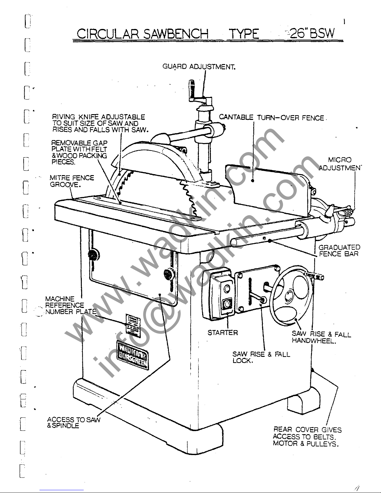
CIRCULAR
SAWBENCH
TYPE
-:-26"
BSW
c'
C'
r
L
c
o
o
tr
fJ"
RIVING KNIFE ADJUSTABLE
TO
SUIT SIZE OF SAW
RISES
AND
FALLS
IAln-U
REMOVABLE GAP
PLATE
WITH FELT
&
WOOD ,.."
.....
('\,,,"-'
PIECES.
MACHINE
0
1
.-,
REFERENCE
NUMBER
PLATE
o
r
[
t
[
[
[
ACCESS
TO
&SPINDLE
~
~
GU~RD
ADJUSTMENT.
CANTA8LE
TURN-OVER
FENCE.
F=:i-2-
.....
MICRO
ADJUSTMEN'
...
:cr=~-r~!!::::~~::::~~GRADUATED
FENCE BAR
STARTER
~
SAW
RISE
& FALL
HANDWHEEL.
SAW
RISE
& FALL
LOCK.
REAR
COVER
GIVES
ACCESS
TO
BELTS,
MOTOR & PULLEYS.
www.wadkin.com
info@wadkin.com
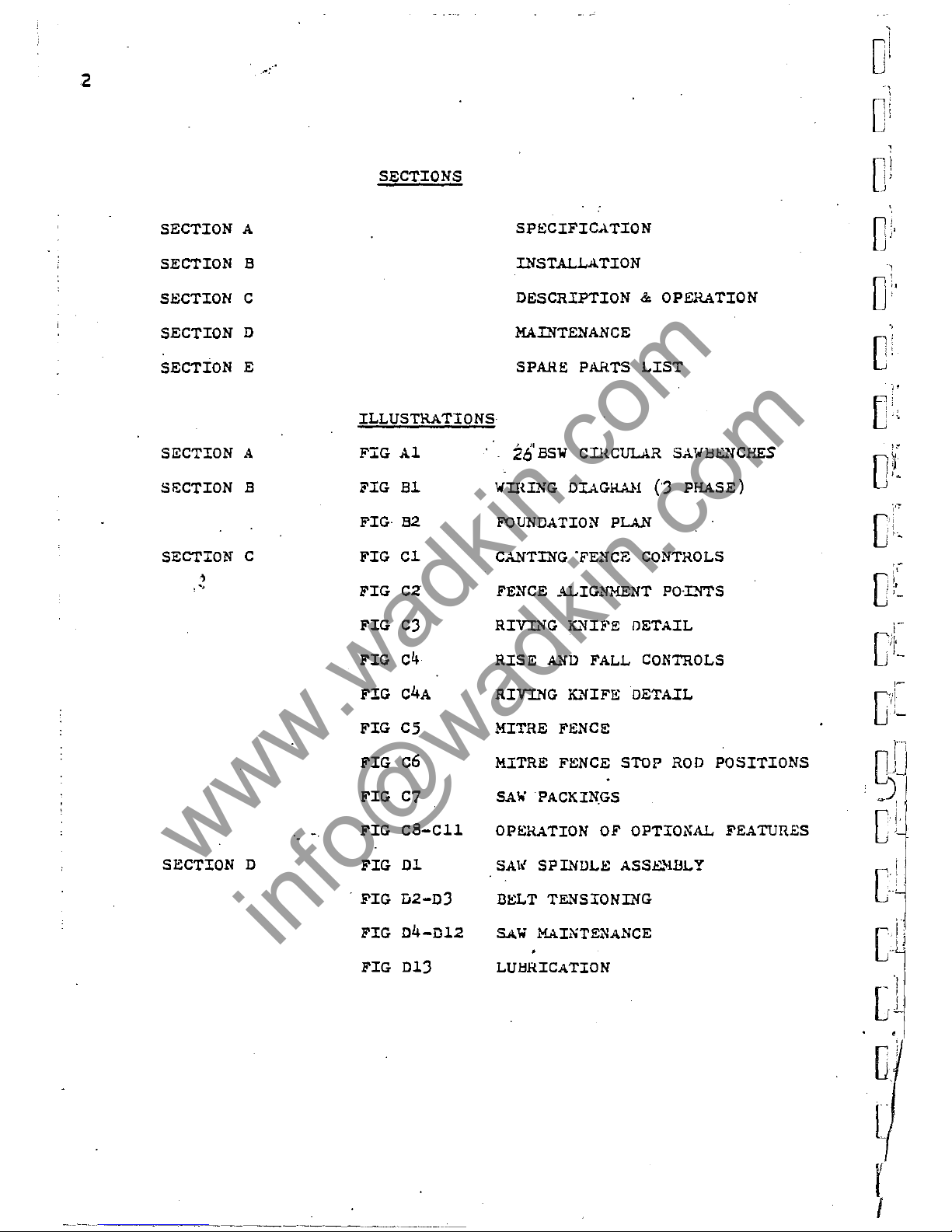
2
SECTION A
SECTION 5
SECTION C
SECTION
D
SECTION
E
SECTION A
SIi:CTION
5
SECTION C
,
, -,
SECTION D
'0
SECTIONS
ILLUSTRATIONS
FIG
Al
FIG
Bl
FIG
52
FIG
Cl
FIG
C2
FIG CJ
FIG
c4
FIG
C4A
FIG
CS
FIG
c6
FIG
C7
FIG
CS-Cll
FIG
Dl
, FIG D2-DJ
FIG
D4-D12
FIG D1J
SPECI:FICATION
INSTALLA.TION
DESCRIPTION & OPERATION
MAINTENANCE
SPAHE
PARTS
LIST
26'
BSW
CI!{CULAR
SAWl:l&'fCHES
WIHLXG
DIAGHA}l
(J
PHASE)
FOUNDATION
PLAN
CANTING
'FENCE
CONTROLS
FENCE
ALIGNMENT
PO'L'fTS
RIVING
K..'1H'E
DETAIL
RISE
~'1D
FALL
CONTROLS
RIVING
K..'1IFE
DETAIL
MITRE
FENce
MITRE
FENCE
STOP
ROD
POSITIONS
SA
....
PACKINGS
OPERATION
OF
OPTIONAL
FEATURES
SAI{
SPL'IDLE
ASSEl-lBLY
DELl' TENSIONL'IG
SAW
MAINTENANCE
LUl::IRICATION
,
O
i
Ii
,
,
C
l,!
"
->
0:'
1
Oi,
e:
'"
"
D
j
{'Oo
i'"
C
r
!'J
..
,-
i
.r
C
,I'
:
1-
.
(1
Dd
, )
Cl
I
[
'~
• J
•
Cl
L
r
I
www.wadkin.com
info@wadkin.com
[
[
[
[
[
[
c
o
o
o·
D
D
[
[
[-
L
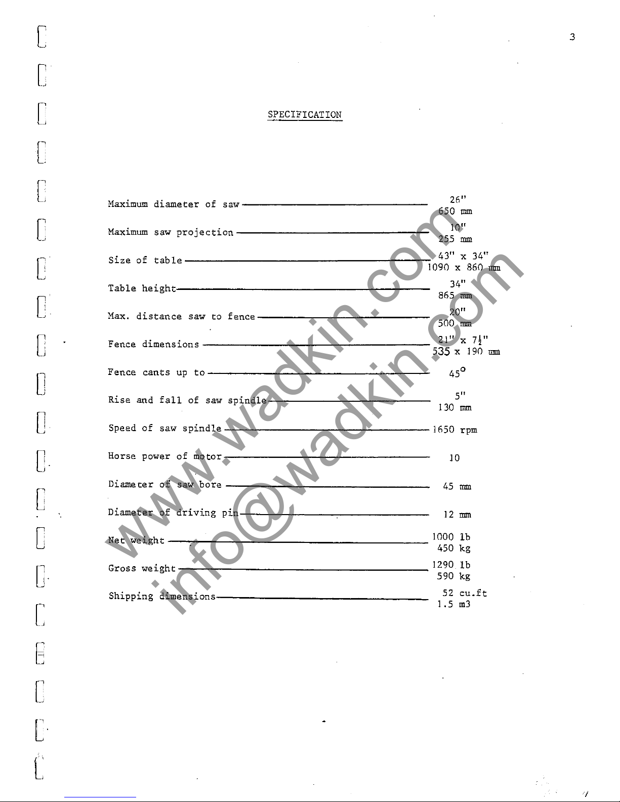
SPECIFICATION
Haximum
diameter
of
saw-----------------
Maximum
saw
projection----------------------------
26"
650
mm
10"
255
mm
43" x 34"
Size
of
table---------------------------------------~1090
x 860
lurn
Table
height-------------------------------------------
Max.
distance
saw
to
fence--------------------------------
34"
865
mm
20"
SOO
mm
21" X
7!"
Fence
dimensions---------------------------------------
S35
x 190
mm
Fence
cants
up
to----------------------------------
Rise
and
fall
of
saw
spindle------------------------------
45
0
5"
130
mm
Speed
of
saw
spindle----
_______________________________
16S0 rpm
Horse power
of
motor-------------------------------------
Diameter
of
saw
bore
___________________________________ _
Diameter
of
driving
pin--------
_______
~----------------
Net
weight----~---------------------------------------
10
45
mm
12
mm
1000
lb
4S0
kg
_
_________________________________
1290
lb
Gross
weight
590 kg
Shipping
dimensions--------
____________________________ _
52
cu.ft
1.5
m3
3
www.wadkin.com
info@wadkin.com
4
SECTION B
Installat
ion:-
Remove
protective
anti-rust
coating
from
bright
parts
by
'applyin~
a
cloth
soaked
in
paraffin
or
other
solvent.
Wiring:-
The
""tor
and
control
gear
have
been
wired
in
before
de"patch,
therefore
all
that
is
required
to
be
done
is
to
connect
the··mains
supply
to
the
starter,
or
isolator
where
fitted.
POINTS
TO
NOTE
WHEN
CONNECTING
TO
POWeR
SUPPLY.
1
-
Check
volta~e,
phase
and
frequency
2 _
It
is
important
that
the
correct
cable
is
used
to
deliv
.. r
the
correct
voltage
to
the
starter.
RUNNING
ON
LOW
VOLTAGE
WILL
rJAHAGE
HOTOR.
J -
Check
main
line
fuses
are
of
correct
capacity.
1.
_
:;onnect
line
leads
to
cnrrect
terminals
(SEE
Wlll.ING DIAGRAH).
5
Check
all
connections
are
sound.
6 _
Check
"pindle
rotates
in
correct
direction.
If
not
reverse
any
two
of
the
line
lead
connActions.
FAILURE
TO
START:-
1 -
Fuses
have
blown
of'
have
not
heen
fitted.
2 -
Isolator
switch
ha~
not
be"n
closed.
J -
Lock
off
or
stop
button
(~her.
fitted)
ha~
not
been
rele1sed.
4 -
Supply
r.ot
available
at
machine.
;>'liJPPAGE flURIl'IG (lPER4TTON & fAlLTJRS
1V
i1ESTART:-
1 -
Ovp.rloarls
have
tripned.
lf
I"'.nd
re-set,
set
hy
pressi"!?,
lmtt,m.
jf
automatic
they
will
r\,-set
after
a
~hort
period.
~ -rtl~e5
ha\'~
blown.
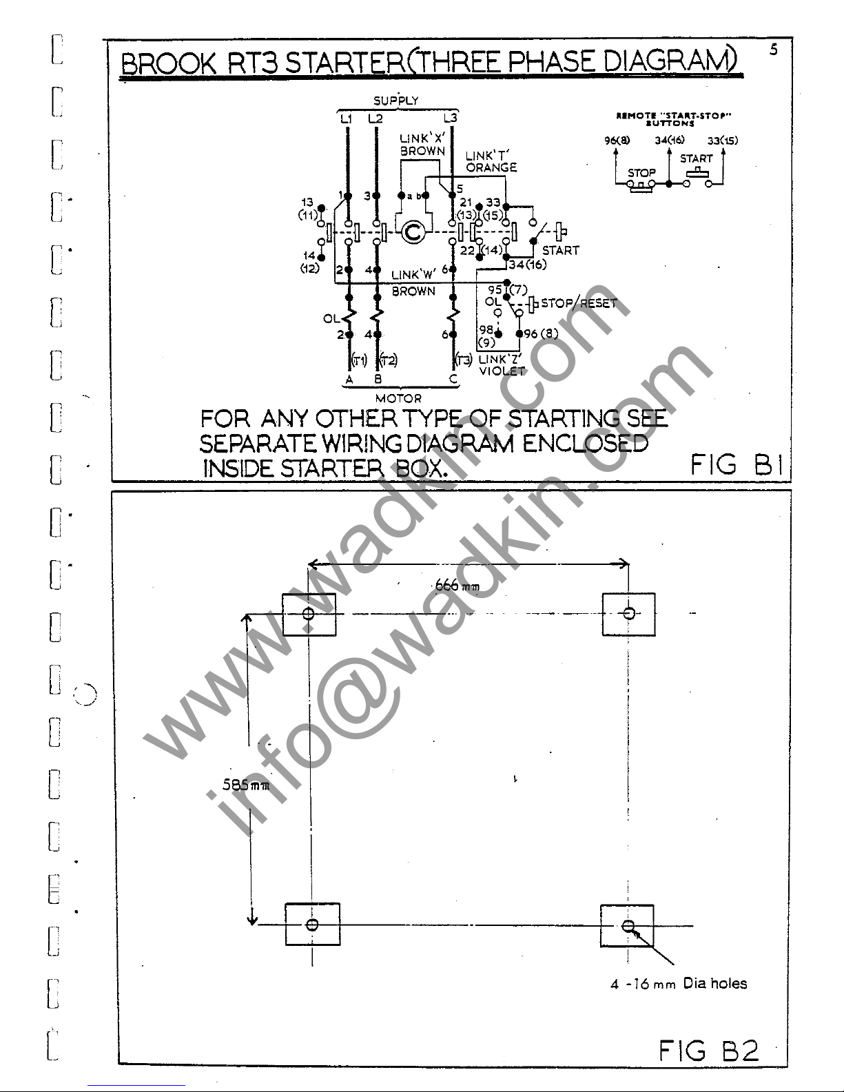
F'oundation:-
The
machine
should
be
levelled
and
bolted
down
firmly.
For
mounting
into
concrete,150
t0250
square
holes
should
be
cut
in
the
floor
and
rag
bolts
fitted,
after
which
the
hol
.. " ..
hould
be
run
·"ith
cement.
For
mounting
on
wood
floor"
coach
bolts
will
be
found
adequate.
(
..
ee
Fig.
B2.)
Cl
;
C
o
o
c
C
0
1
0
1
j
C
c:
0
' i
!_
J
[j-
[
fl
U·
www.wadkin.com
info@wadkin.com
[
[
[:
c-
c-
c
[
.,
[
c
o·
D'
C
D
'\
-'.
---/
0
C
D
E
[
[
[
BROOK
RT3
STARTER(THREE
PHASE
DIAGRAM)
SUPPLY
,
L1
L2
L3
LINK'X'
BROWN
LlNK'T'
l ORANGE
"5
13
);
3 • b
21
33
(11)h
(13~e5)~
il
--n---o-
c
---0-
-----0
-{P
14~
22 14) .
START
(12)
2 4 LlNK'W' 6
34(16)
JI.IMOTI
"ST"'''T.STO'''
aUTTCNS
96(a)
34(~61
33(15)
t
_.___
t S
SlTAR.T
t
~°oJ
BROWN
9S~~7)
>
~
>
OL
-1PSTOP/RESET
OL~
~
•
~
2 4 6
98,
96(8)
(9)
j"3)
LlNK'Z'
A B C VIOLET
-=---~~~
MOTOR
FOR
ANY
OTHER
TYPE
OF
START1NG
SEE
SEPARATE
WIRING
DIAGRAM
ENCLOSED
5
INSIDE
STARTER
BOX.
FIG
B I
l
E
)1
·666
mm
...--l-e!-+
----
.... -
....
---·-+~-l
595 m 'Ill
i
,
-l-
I
I
I
I
~l
!
-
.
I
4 -16
mm
Dia holes
FIG
B2
www.wadkin.com
info@wadkin.com
b
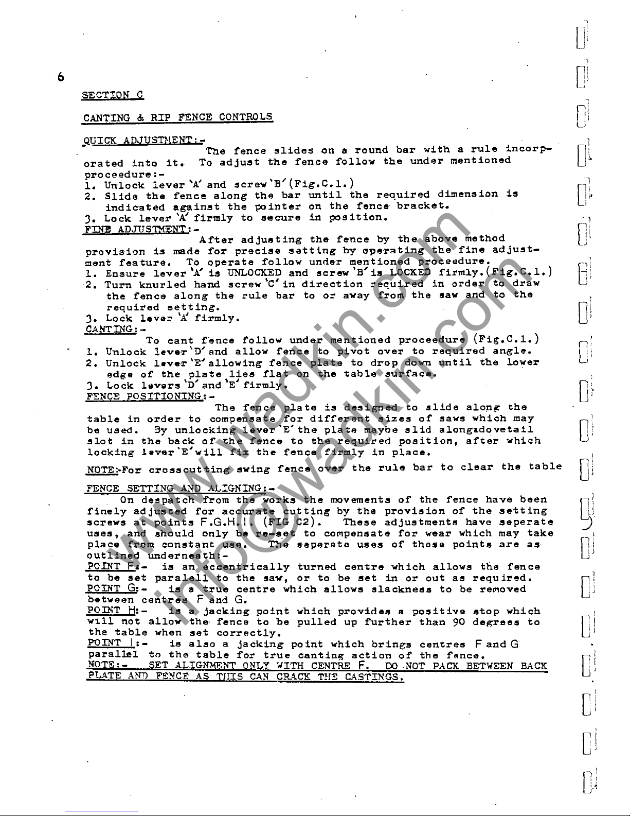
SECTION C
CANTING
&
RIP
FENCE
CONTROLS
QUICK
ADJUSTI!ENTi-
-
The
~ence
~lides
on a round
bar
with
a
rule
incorp-
orated
into
it.
To
adjust
the
~ence
~ollow
the
under
mentioned
proceedure:-
1.
Unlock
lever
'A'
and
"crew
'B'
(Fig.
C.1.)
2.
Slide
the
~ence
along
the
bar
until
the
required
dimension
is
indicated
against
the
pointer
on
the
~ence
bracket.
J.
Lock
lever
'K
~irm1y
to
~ecure
in
position.
FINE
ADJUSIMENT:-
A~ter
adjusting
the
~ence
by
the
above
method
provision
is
macie
~or
precise
setting
by
operating
the
~ine
adjust-
ment
~eature.
To
operate
~ollow
uncier
mentioned
proceedure.
1.
Ensure
lever
'AI
is
UNLOCKED
and
~crew'Blis
LOCKED
~irm1y.(Fig.C.1.)
2.
Turn
knurled
hand
~crew
'C'
in
direction
required
in
order
to
draw
the
~ence
along
the
rule
bar
to
or
away
~rom
the
saw
and
to
the
required
eetting.
J.
Lock
lever
'J:
~irm1y.
CANTING:-
To
cant
~ence
~ollow
under
mentioned
proceedure
(Fig.C.1.)
1.
Unlock
leva·r
'D'
and
allow
~ence
to
pivot
over
to
required
angle.
2.
Unlock
1.ve·r
'E'
allowing
~ence
plate
to
drop
down
until
the
lower
edge
o~
the
plate
lies
~lat
on
the
table
sur~ace.
\
~
\
~
J.
Lock
1avers
D
and
E
~irm1y.
FENCE
POSITIONING:-
The
~ence
plate
is
de~igned
to
slide
alOng
the
table
in
order
to
compensate
~or
di~~erent
sizes
o~
"aw~
which
may
be
used.
By
unlocking
lever
'E'
the
p1at
..
maybe
slid
a10nglldovetai1
~lot
in
the
back
o~
the
~ence
to
the
requiren
position,
a~ter
which
locking
lever'E'wi11
~i~
the
~ence
~irm1y
in
place.
NOTE:'!'or
crosscutting
swing
~ence
over
the
rule
bar
to
clear
the
table
FENCE SETTING
A~D
ALIGNING:-
On
de~patch
~rom
the
works
the
movement~
o~
the
~ence
have
been
~ine1y
adjusted
~or
accurate
cutting
by
the
provision
o~
the
setting
screws
at
points
F.G.H.I.
(FIG
C2).
These
adjustments
have
seperate
uses,
and
should
only
be
re-eet
to
co~pensate
~or
wear
which
may
take
place
~rom
constant
use.
The
seperate
uses
o~
these
points
are
as
outlined
underneath:-
POINT
F.-
is
an
eccentrically
turned
centre
which
allows
the
~ence
to
be
~et
para1e11
to
the
sav,
or
to
be
set
in
or
out
ae
required.
POINT
G;-
is
a
true
centre
which
allows
slackness
to
be
re~oved
between
centres
F
and
G.
POINT
H:-
is
a
jacking
point
which
provines
a
positive
stop
which
will
not
allow
the
~ence
to
be
pulled
up
~urther
than
90
degrees
to
the
table
when
set
correctly.
P'OINT
I;
-
is
a1,,0
a
jacking
point
centres
F
and
G
parallel
to
the
table
~or
true
cant
o
O
l
"
1
Cl:·
6
·:·
~,
It
0.
1
, 1
,
0·
"
,
0
,
I'
.1
I
Or
)
@
Cl
O
f
i J
I
~.I
Ul
nf
Uj
,
[
...
t,
; :
,
I
',
.'
; i
J.1
www.wadkin.com
info@wadkin.com
[
7
[
[
C-
C
C
[
0
c
.
FIG-Cl
O·
0
C
C
lOO)
.-./
0
['
-'
[
J
E
.
[
[
FlGC2
[
www.wadkin.com
info@wadkin.com
8
RISE
AND
FALL
CONTROLS:-
By
turning
handwheel
'J'
(fig.
C4 ) the
"aw
may
be
r>lised
or
lowered
between
the
maximum
and
minimum
oosition
AS
given
in
section
'A'
specification.
Under
no
circumstances
should
this
dimension
be
varied.
It
is
important
after
operating
the
rise
and
fall
thAt
lever
handle
'K'
is
locked
firmly
before
running
the
saw.
o
0
'",1
, )
.,
"
The
rise
And
fall
hanrlwheel
is
connected
through
pivoted
yolks
at
1
points
A.
&
B.
(FIG
c4.)
At
the
hanrlwheel
end
of
the
screw
a
thrust
Oil'
race
C
is
fitted
to
give
free
ro,tation
when
in
use.
It
is
therefore
J
important
that
the
pivots
and
"crew
are
cleaned
and
luhricated
regular-
,
ly
and
that
the
tiru"t
race
is
oiled
Accorrlin".
to
the
maintenance
sCheduleD!'
!tIVING
KNIFE
PLATE:-
The
riving
knif
..
pIa
te
is
situated
behind
the
"a'"
in
the
saw
co",-
pa'rtment
'0'
(fig.
C4A)
and
allows
the
riving
knife
to
rise
anrl
fall
with
the
"aw
at
a
set
clearance
to
the
saw
teeth.
It
is
important
that
th",
area
s,urrounding
thA
radial
"lot
cut
in
the
p.lflte
'be
kApt
clean
>lnd
well
lubricated
t'o
give
free
movement.
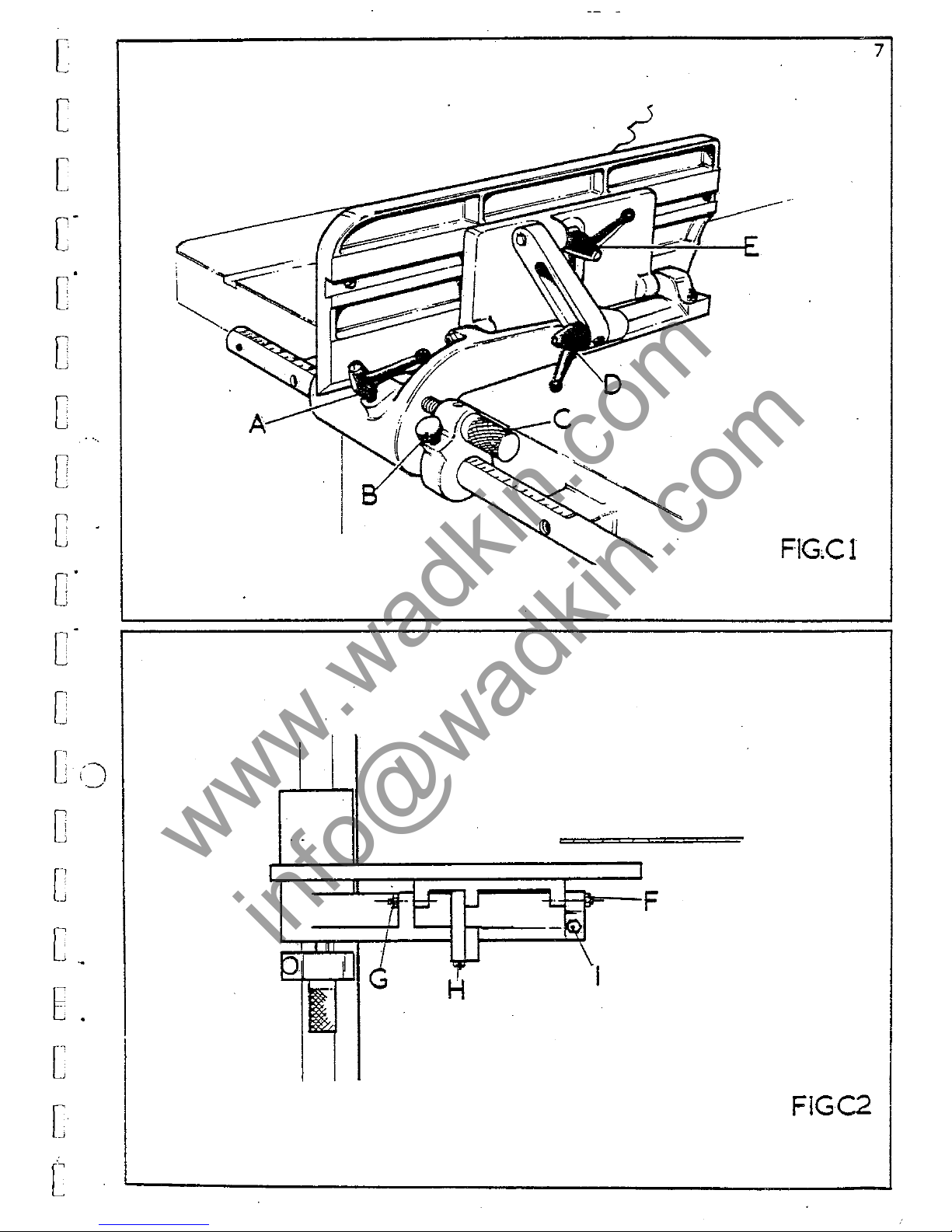
HIVING
KNIFE
HOLDEi1.
DETAIL
The
riving
knife
is
"urplied
in
the
invertAd
position.
fit
upright
adoptine:
the
following
proceedure:
-(figC3)
Remove
and
1.
Fit
knife
into
groovt!rl
packln,,,:
piece
'E'
and
bolt
up
to
solid
1'acl<-
ing
piAce
'F'
'~ith
thelO'rrom
nuts
'G'
prov:ldAd.
2.
J'II
.,
1.
'G'
ha"
With
saw
in
plaee
set
knife
to
clear
around
saw
teeth
approximatelY
(6mm)
and
lock
firmly
in
plAce
with
nuts
'G'.
If
the
'knife
is
not
in
line
with
th
..
sa""
partially
slacken
nuts
and
jack
packing
piece
'F'
out
,~ith
/7,rub
screw"
'H'
until
the
knife
e~ual
overhand
either
side
of
the
saw
blade.
Lock
nuts"G'
firmly.
XOTE:
- REFORI':
RUNNING,
ADJUST
SAl
..
GUARD
TO
GIVE
~,AXD1UN
PROTECTIO:-l
AND
TU
CLEAR
SA'!.f
BLADE.
no
NOT
RUN
K4.CHINE IGTHOUT
GTTARD
IN
POSITION.
U!PO!{TANT:,.
ENSU!{E THAT
RIVING
KNIFl!:
BLADE
IS
COR,\ECT TrrrCK±'fE§S
FO!
SA"·
rSEI)
G
,(~\
®
-
-
~
\1
\
E
Riving Knife
H
Plate
Riving Knife
FIG
C3,
Ol
B
',r
· .
·
,
"
0
','
, I
! i
0
'
· .
\ i
•
!
0
1
11
I
0\
O
,,!
i \
C
i
:V
0
·;
u
,]
[jJ
QJ
C
"
:
, j
•
0;
www.wadkin.com
info@wadkin.com

[
[
c
[
' .
-'
c-
c
[
c
C
0-
c-
C
[-':
c
[
[
6
[
[
[
... ~.J
9
A
.
FIG
C4
FIGC4A
I-<iv,...., knife plate
www.wadkin.com
info@wadkin.com

10
o
HOUNTING
SAWBLADES:-
When
mount
in..;
saw"
the
llndermentiancd
proceedure
sho"ld
be
.
0'
, ,
,
)
t'ollo",ed:-
j
1.
Isolate
machine
2.
Remove
table
insert
and
raise
the
SRW
sr~nrllR
hOl1sin~
into
the
top
position.
3.
Remove
spindle
nut
(left
hand
thread)
~nd
front
saw
fl~nKe
from
spind
1 e •
4.
Select
blade
required
depending
on
tYro
of
work
wh
ich
is
to
be
done.
Check
the
hlade
is
in
good
condition
and
free
from
dirt,
sawdust
and
,-;::um.
especiAlly
where
it
will
he
gripped
by
the
saw
flan,o:e.
Hount
saw
on
the
~pindle
checking
that
the
face
of
the
hack
saw
flange
is
clean
~nd
thRt
the
saw
b6re
and
pin
hole
centres
fit
correctly
onto
those
on
the
flange.
~.
Ch",ck
that
the
saw
teeth
poi.nt
towards
the
front
of
the
,""chine
be-
fore
re·placin/?,
the
flanl1:'"
Rnd
loekin"
UP
firmly
with
the
spindlp.
nut.
IHPO.nA.l'lT:-
ENSURE
SPINDLE
;lUNS
IN
COaRECT
'lIRo;CTIOI'.
R:::Ft:R TO
Sr~CT
...1!
ELECTRICS
L
'{QTE:-
IF
TllI,
FL.\:-IGE
OR
5,\1.:
FACES
ARE
'lOT
CL8A'I
THIS
CAN
C,\:"SE
VIJHV.1'IO~
DUE
TO
THE
SAW
RUN:-IING
OUT-QF-TRliF..
}I
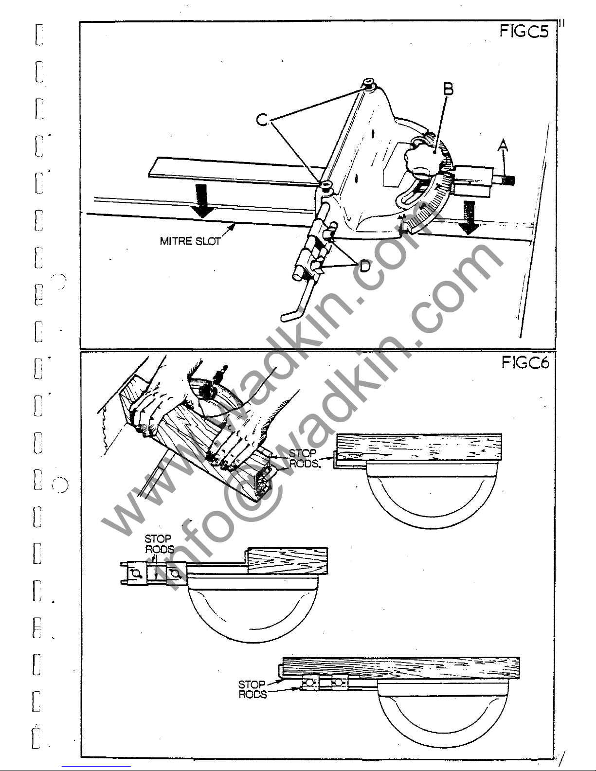
ITHE
FENC:; (
!if.:
~
j)
.-t
E'URA.
)
The
mitre
fence
is
fitted
into
the
/?,rOOY"
provided
on
the
S"N
t"hle,
Nhieh
should
he
kert
clean.
A
scale
is
proyided
tn
indicate
accurate
setting,
and
a
positlve
stop
'A'
is
incorporated'
in
the
sr.ale
to
I;iv"
quick
sPotting
al;
qOO
and
4S
0
to
the
saw.
Th"
rlastic
""nd"heel
'fi'
locks
the
mitre
fence
firmly
in
any
position.
Accurate
repetitive
cutting
~an
he
obtAined
hy
USP
of
th"
stop
rods
(fil1:.
CS.)
The
rods
are
held
in
the
fence
with
the
thumbscrews
'C'
and
the
stop
rods
hy
the
two
clamps
'D!
Tb
adjust
the
stor
rods
sl~cken
cl~"'ps
'c'
~nd
'D'
and
slide
the
rods
into
th",
position
reqlJired
as
illustrRted
in
(fi~.
C6.)
.
,.,
,
0
1
[1
:
O·
i
, .
I'
i
0
:
y
I
D
·!
[,j
O
"l.
, ,
(_1
oJ
gJ
[
"
.'.
' ,
i J
j
I
C
"
, ,
, :
D·
www.wadkin.com
info@wadkin.com
[
[
[
[
' .
.
~
c·
c
[
c
[
o·
c
c
c ,
..
_"
;
.....
'
C
·
-'
[
[
E
[
[
c.
MITRE
SlOT
STOP
RODS
B
~.--.-
-.
.F"
FIGCS
11
I
I
,
I
FIGC6
www.wadkin.com
info@wadkin.com

12
SA\;
PACKING.
It
is
usual
to
provirle
a
saw
hl"de
with
some
form
cjf
packinr;,
hut
it
is
not
intenrled
that
this
packing
be
userl
as
a
~uirle
for
bucklerl
or
ou~-of-true
sa*s.
The
idea
of
fitting
packin~
piec~s
into
the
tahle
and
gap
plate
is
to
steady
the
saw,
but
it
should
he
noted
that
the
packing
must
not
be
tight
"s
this
will
,o:enera
te
heat,
resulting
in
"
consequent
lo~s
or
ten~ion
in
the
blarle.
The
arrangement
of
the
saw
pAckings
"re
in
such
a
way
that
a
h"rd-
wood
mouthpiece
of
"
lene;th
extending
beyond
the
depth
of
the
saw
teeth
retains
the
felt
packin/!:
pieces
in
pl"ce.
Also
wood
strips
secured
to
the
underside
of
the
tahle
and
to
the
front
of
the
I';"p
plate
support
the
felt
in
position.
At
the
rear
of
the
gap
plnte
anrl
tahle
similar
wood
strips
close
the
~aw
p:ap
and
provide
a
/,:llirle
for
the
saw.
(SEE
DIAlSH,\NS
OPPOSITE.
)
It
shoulrl
he
noterl
thAt
after
some
time,
the
p"ckings
will
need
to
he
renewecl,
ancl
shol1lrl
not
he
"llowerl
to
fall
into
b"rl
cnnrlitif)n.
The
provision
of
the
felt
inserts
allow
applicatinn
of
"
s,",all
amount
of
luhricatin,o:
oil,
which
not
only
cl""n"
the
s"w,
hut
"Iso
re-
rluces
he"t
and
burning
whilst
runnin.o:.
It
is
th"refore
import"nt
that,
at
every
opportunity,
the
felt
pieces
are
luhricaterl.
"
NOTE,-
REP1...ACE~!EYl'
LENGTHS OF EELT
12 x 11 x 150
[J
I
0
1
)
D.
!
I:
,
I
ii
0
"
, '
0
1
q-
!
0
1"
I i
i-l
Dl
OJ
~
O
il
\-
0
'
!
I i
u
0-1
o
L
www.wadkin.com
info@wadkin.com

[
[
[
c:-
C"
c
[~
c
[
c-
C"
c
c·~)
c
[
[
E
[
[
[
'
~~
Hardwood
Saw
~
I
lA
.-p
Li..-4\mtHtiti
1
I
I
-
~====:::::t-WmJt_
:
,I
i
I 1
I [
I~J
--..,
[
[
.""'V".Jk====ti~Pf""
:1
Hardw 1
:(f)
~le
Bt.L~H--.~
I
1
[
Felt~J:=====t=t:~
FI
SECTION,
AA
Saw
'"---Screw
SECTION,
'BB
Saw
SECTICN,
'CC
13
www.wadkin.com
info@wadkin.com

I
....
B
E
A
.-'/
./
FIG
CS
FIG
C
11
SPINDLE
ERAKE:_
This
device
is
operated
from
the
brake
lever
'A'
situated
next
to
the
rise
and
1'all
handwheel.
It
is
connected
to
the
brake
pad
by
means
of
a
cable
'B'
leading
from
the
operating
lever,
and
is
spring-loaded
to
relieve
tension
when
hand
pressure
is
reljeved.
To
tension
the
cable,
turn
the
knurled
nut
'C'
on
the
lever.
Wher~
e'xee!!~ive
~laekness
is
to
be
removed,
unlock
the
grub
screw
'D'
on
the
pillar
at
the
spindle
end
and
pull
cable
through,
re-lock
grub
screw
and
tension
cable
as
mentioned
above
with
knurled
scre~.
When
re-
placing
brake
pad
it
is
important
that
new
rivets
are
used
and
that
the
rivet
heads"are
below
the
sur1'ace
01'
the
pad
material.
Po
not
allo~
brake
pad
to
wear
down
to
rivets
as
this
will
score
the
sur1'ace
01'
the
special
pulley.(FIGC11}
i!
u
)
[
' '
I:
, '
.
.J
Cl
1
fl
t
L~
Bi
- ,
Di
o
o
o
Ol
)
~j
fJ!
I
n
J
0
,
\ r
r~
c
www.wadkin.com
info@wadkin.com

r
[
[
[-
r~·
.
[
[
r:
[ .
[.
c-
[
[,'
, ,
[
[
[
E
[
[
L
.j
1$.
S:ECTION
"c"
MAINTENANCE
(/
www.wadkin.com
info@wadkin.com

\
16
SECTION
D.
-
HAINTENANCEj-
During
th9
op9rating
life
of
the
~awbench
it
may
be
fOllnel
necess<'lry
..
,
to
replace'worn
or
damaged
pRrts
(Le.
ball
race~.)(
1'0
unrlertak)e
this
n.,l
proceedure
follow
the
undermention
..
<l
instrllctinn~
•
.sEE
FIG
D
1.
lJ
1.
2.
3.
ISOLATl':
MACHINE
ELECTRICALLX
BEFOj(E
AITEHPJING
ANY
·'ORK.
RENon
GA.P
PLATE,
SAl.
AND
SAW
SPINDLE:
FRONT
,\N')
RF:J\R
COVERS
FRO~r
TilE
MACHINE.
SLACKEN
ANn
HENon
V_ROPES
FRON
PULLEYS
A.1W
nRHOYE
TURNnTJCKLE AND
TENSION
STUDS
.\FTER
PACKING
HOTOR UP
;\S
SH01JN
IN
(FIG
D.2.)
4.
'.HND
SAW
CARRIAGE
INTO
HIDWAY
POSITION.
6.
8.
n
..
10.
11.
REHOVE COUNTERSUNK SCRE1.
AND
\{
ASHBR '
A'
ANn SLACKBN
GH1JB
SCREWS
'R'
IN
PULLEY
'C'
AND
REHOVE.
RE}IOVE KEY
'D'
AND
DISTANCE
PIP-CE
'E'.
RE:HOVE
CIRCLIP
'F'
AXn HOTOR
TI::NSION
BRACKET
'G'
ANIJ
1JN~CnE:1{
Ai'!D
REHO
YE
DUSTCAP
'H'.
WORKING
AT
TilE
FRONT
OF
THE
SAW
SPINDLE,
HE:·l0VE
NUT
'I'
(L.H.THHEAD)
AND
SA"
FLANGE
'J'.
UNSr.:REW
SAlo/
FLANGE
'K'
(L.IJ.THH$A1).)
HEHOVE
RIVING
KNIFE
PLATE*A.'In
LI~,
A.'!D
UNSCHEW '\:'\1l REHOVli:
DUST
CAP
1
L'
•
PL~CB
A \.OOOEN
DRIFT
ON
THE
PULLEY
E:Xn
OF
THP.
Sl'I:'<nLr;
~m
fJltIVE
THI,
SHAFT 'THROUGH
THE
HOUSING.
11Y
OOlNG
TIiIS
TlIR
SPINDLE
IHLL
!':hEHGE
FRON
THE
H01'SI:-l'G
\;JTlI
TIlE
SAl{
EN!)
REAIU.'IG
ON
IT.'JIUVE
THI::;
m;AR-
ING
PItON
THE
SHAFT
AND
RE-INSERT
SHAFT
INTO
HOL"SIXG lGWC1:T.NG
Sf'INDU:
TlTilOlIGH
''iITH
HANHER
ANT)
DRIFT
1'0
I~E}IOVE
THE
PlTLLSY EN':)
nEARING.
[
11
J '
0
1
SI
Dj
U
-l
i
, ,
Or
0
,\
I J
1'0
re-a~~e",ble',
rever"e
above
proc"
..
<lut"e
ensur1.n.:
all
ori",inal
p"rts
D.J'I
are
thoroup.:hly
cleanerl
out.
* ' ,
It
shoulrl
al~o
be
note<l
th"t
the
two
locknuts
on
thp.
rarli"l
s~ot
in
the
rivinp;
knife
plate
~hould
onlv
be
tirhtenp.rl
9nnu,[h
to
prClvirle
a
=i<l
..
Qj!
for
the
motion
of
the
plate
"nrl
not
to
clamp
or
lock
the
pl"te
in
oo"i-
)
ti.on.
DJ
W
o
[
o
www.wadkin.com
info@wadkin.com

r
[
[
r·
c
c·
r
e
c
[
C"
C"
C
[
(-\
[
[
[
E
[
[
[
j.
17
'1
GJ
o
www.wadkin.com
info@wadkin.com

18
BELT
TENSION:-
On
all
",,,chine~the
drive
from
the
",ain
motorto
the
,.'aw
spindle
is
by
means
of
four" ALPHA
500
type
"V"
Belts.
To
ensure
maximum
effi
ciency
and
life,
of
the'se
belts,
t.t
is
importa
nt
tha
tthe
correct
belt
tensi'on
is
maintained
at
all
times
from
new,
especia'lly
in
the
"running
in"
period.
To
tension
the
belts
folIo\{
the
undermen-
tioned
proceedure.
(SEE
FIG.
0.2.)
By
turning
turnhuckle
'A'
linking
the
tension
studs,
the
centre
distance
of
the
pullevs
can
he
incre"sed
to
provide
greater
tension
on
the
belts.
To
achieve
the
correct
tension,
m~asure
the
centre
distance
of
the
J)ulleys
(FIG
DJ.)
and
adjust
with
the
turnbuckle
until,
whilst
apl'lying
a
force
at
right
aneles
and
centr'll
'11ong
the
belt,
'the
deflec-
tion
is
not
greater
than
O'S
per
25-.mmot'
s,pan
-(e.g.S84
sl'an
=
11Smm)
de,flection.)
REPLACING
BELTS:-
[J
r,i
1]1
O
J
; ,
f
-l
I,
e
To
replace
belts,
decrease
pulley
centre
distance
by
screwing
buckle
and
thu"
relievi.n~
tension
on
the
belts
for
their
removal.
I<a'rds
retension
as
giv,m
above.
turn-
nt
AfterlJ
POINTS
TO
NOTE WlIE);
HAINTAINING
BELT
nRIVES:-
1.
2.
).
4.
5.
6.
ALWA
YS
HAINTAIN
COimECT
BELT
TENSION
Q
REPL,\CE
1¥OHX
m:LTS
WITH SANE
TYPE
AS
SPEClFIED.
AU1AYS
REPLACE
'mllN
OH.
D.tHAGED BELTS
INMEDIATELY.
ENSURE
pm
LEYS
Ai{E
COtl.HECTLY
ALIGl\ED.
DO
NOT
PRISE
HELTS OVER
P'ULLI!."YS
1iITIl
SCHE1i
DRIVERS
Oll.
OTHER SHARP
IMPLEMENTS AS
TInS
CA:,
DAMAGE
BF;LTS.
ENSTTRE
PULLEY
GHOOVES
AND
BELTS
AHE CLEAN
AND
REl-tOVE
A:-IY
(JIL,
RUST
OR
DUTIRS
'.l!ICIl
ARE
PRESENT.
O
,!
I'
(ll
u!
0
1
,
Di
0
1
I I
i-l
I
DJ
Q
I
, I
-J-~
0
1
C
[
www.wadkin.com
info@wadkin.com

[
[
[
[
[
[
[ ,
[
[
[
c
[
[
[
[
[
t
[
[
[
·
·
·
·
,
.,
'
........
7
Method
of
pacl<.ing.up
motOr
for
remcval of
tension screws as
outlined in section
01
I
I
(~~--t--t---A
I
I
I
I
I
FORCE
FIG
02
FIG
03
DEfLECTION
O°,5mm
PER
25mm
OF
SPAN
19
www.wadkin.com
info@wadkin.com

20
SAW
HAINTENANCE:-
Efficient
operation
of
a
ctrcu~ar
saw
depends
on
true
runnine
of
the
saw
~pindle,
and
the
saw
flanges
being
perfectly
square
to
the
axis
of
the
spindle.
Th"
saw
must
also
run
at
the
correct
peripheral
speed
to
ensur~
straieht
cutting.
HANGING:
-
'RanginR
down'
should
he
done
on
a
new
saw
or
any
saw
after
the
fourth
or
fift'h
sharpening.
To
range
dow·n,
feed
a
square-edged
abra-
sive
block
in
a
wood,,"
holder
(FIG
04.)
lightly
against
the
saw
teeth
whils't
running.
The
saw
should
then b ..
removed
and
the
tops
of
the
teeth
filed
lip,htl'Y
to
remOve
the
rangin~
marks.
SAW
SiiARPENING:-
Do
not
run
a
saw
when
blunt.
To
re-sharpen
by
.hand,
hold
the
saw
in
a
vice
as
shown
in
(FIG
D5.)
1ii.th
rip
saw
teeth,
chisel
edges
and
sq,,"re
faces
are
required
(FIG
06.)
Sharpen
hy
e'ivjn1"
each
tooth
an
equal
number'
of
strokes
with
a
flat
file.
At
the
same
time,
file
the
gullet
of
the
s"w
in
the
s'ame'
manner,
takinp;
care
to
keep
the
gullet
well
rounded.
1;
Lt'h
cross
cut
saw.s
points
are
needed
with
hack
and
front
l>evels
as
in
(FIG.
D7.)
In
the
course
01
repeated
filing,
saws
lose
their
original
s·h"p
..
and
the
gulle·ts·
become
shallow.
To
restore
the
original
profile,
it
i..
ne·cess·ary
to
grind
the
saw
on a saw-sharpen
in",
machine.
SETTING:-
The
a",ount
of
set
should
be
sufficient
to
give
clearance
to
the
saw
body
so
th"rei~
freedom
fr~m
friction.
Saw
teeth
are
generally
'spring
set'
(i.e.)
the
teeth
are
bent
alternately
to
the
right
or
left
as
shown
in
(FIG
OS)
For
good
sawinp;,
this
amount
of
set
should
he
e<"Jual
at
each
side
or
els.e
the
saw
will
run
to
one
side.
To
check
the
set,
cut
into
a
piece
of
timber
where
the
result
"hould
he
a
small,
even
triangle,
as
seen
in
(FIG.
D9)
The
aMount
"1
set
varies
according
to
the
t.imher
being
cut,
hut
is'
usu"lly,
.Jmm
- 4mm,
.
We
can
supply
a
sm"ll
machine
for
precisely
settin",
saws
as
shown
in
(FIG
010)
This
device
will
accept
saws
up
to
J6"
in
diameter,
and
indicates
the
amount
o~
set
by
micrometer
dial.
For
hand
setting,
small
devi.ces
can
he
supplied
where
it
is
felt
that
the
nl1mher
of
saws
used
does
not
warrant
a
machine
(SI';':
~'IGs.Dll
&:
012.)
45
mm
Bore
STANDARD
S.A.W
AND
PIN HOLE CENTRES
15
mm
Bore
"1
[]I
n,!
u
or
[
ll
J:
01
ru
01
[
11
JJ
0
,
u
DJ
[
~
, :
www.wadkin.com
info@wadkin.com

[
[
r
~
[-
['
[
L
C
[
c-
c-
r"
L.
[,
[
C
[
E
[
[
[
l t
".j
-
-------.-.--.--~
-
.. , ...... ___
-t
_
...
-2"".-,.-.
•.
FIG
04
FIG06
Hook
Top bevel
a
gle10
0
RIP SAW
==s;}~.
:::::::z:;;;
:fls=e:=~
:::::;;:s~f8~dY
J • I +
saw
Saw cut . Set
Area
of
tooth
set-over
shown shaded
--~
FIG
08
FIG
010
FIG
05
FIG
07
FIG
09
F!GDII
10
18'
FIG
012
Clearance
angle
43
0
CROSSCUT SAW
----
1 I
I I
" .
15
20
www.wadkin.com
info@wadkin.com

FIG
013
c::-::J
L.
..
.-e
',.1,
.
LUBRICATION
DIAGRAM
-'I,..
,
----
I
llll
A4
i--t-L
__
{r.'.I
,-----V-:
\
1-
1
~~\'I
c
\ I
\ I
0"">+--
(,.n--
-----"'i:
--?,
(y
->-... .......
/ \
/)/
\
~J
J
,
"--D
'-
./
....
C_J
£---,-~
f-_
...
J
L
__
f__
_J
L _ c
1,_J
\t;=_l
L
__
'
't_
A-
Oil
and
clean weekly.
B-Oil
weekly.
C-"THRUST
RACE:'oil
weekly.
D-Grease-two
shots
each
end per
year.
t
Dust Outlet
20Qx130
I -
I l
I I
I
I
I I
t I L
__
i
Q:
L J
(.-1
!---
~.
L_.J
c::=J
[]jCL..J
r=J
.---
1
-----,
".
,-
~
A---.I.
.A
l.w..J
L-_._j
-.----;
l :J
c::J
~--
)
r----1
l
___
.
..-l
...
_.)
www.wadkin.com
info@wadkin.com

[
[
[
c-
C"
c
c
c
[ .
C
[
[.
.
[~
[.
[.
[
E
[.
[.
[
23
u "
SECT'ICN
E
SPARE
PARTS
LISTS
www.wadkin.com
info@wadkin.com

1
24
ot
-,
MAIN
BASE
ASSEMBLY
et
,
0
1
i I
'REF
PART
NO.
NO.
NO.
OFF
DESCRIPTION
O!
I
BS\,
753
MAIN
BASE
,
2
BSI'
750
I
TABLE
3
BSW
752 I
GAP
PLATE
ni'
, i
4
BSX
12
I
SPINDLE
PULLEY
COVER
5
BSW
751 2
BASE
FEET
6
BSW
137 I
FRONT
COVER
7
BSW
27
BASE
COVER
Ol
;
(8
BROOK
RT 3 STARTER}
(
PLEASE
STATE
VOLTAGE,
PHASE & FREQUENCY
1
9 I
WADKlll
BURSGREEN
NA'!EPLATE
1
['1'
· ,
1
:,
10 2
REAR
\,000
SAW
PACKrnGS
I I
2
FRONT
WOOD
SAW
PACKJi~GS
12 8
No.
10
WOODSCREHS
13
4
MI2 x
30
mm
LONG
HL~AGON
BOLTS
D:
14
4
12
mm
WASHERS
15
2
10
mm
DIA x
25
mm
DOWELS
16
2
M8 x IS
!IIIll
ROUND
HEAD
SCREWS
,
D"
I I
· .
17
4
MIO
x 35
mm
LONG
SCREWS
20
8
MIO x 25
DlII'
HEXAGON
BOLTS
21
2
116
x I 0
nnn
HEXAGON
BOLTS
22 2 6
mm
WASHERS
Q!
\ :
, ,
I
23
BZG
70 I SPRING
GUARD
CLIP
24
2
M6
NUTS
25 2
WING
NUTS
Oi,
26 2
10
nnn
EXTERNAL
CIRCLIP
I
27
I
M8 x IS
mm
LONG
ROUNDHEAD
SCREWS
28
2
1/8"
DIA
BRASS
RIVETS
29
3
'
2BA
x 20
nnn
LONG
SCRElfS
0:
,I,
30
2 DRIVEPINS
!
D'
, ,
!-~j,
,
WHEN
ORDERING
SPARE
PARTS
PLEASE
QUOTE
PART
NUMBER
AND
SERIAL
NUMBER
OF
MACHINE
0
· ,
!,-),
,
0:
, ,
'--"
, I
Di
:-~.
(
· '
, ;
,
>~
C
!
..
;
C
' ,
'-
;
L
.
''l
www.wadkin.com
info@wadkin.com

'[
www.wadkin.com
info@wadkin.com
\0
r
L
re
f"
~
C·
TI
t
[
(--
.J
i"
6~
-------.2
. -.
..
._..-,..--.,----
'~
.
~
~.
---
-..
-,-.,
4
0
~'
,
,
8
L
[
C
t
l
[
5

REF
NO.
40
41
42
43
44
45
46
47
48
49
50
51
52
53
54
55
56
57
58
59
60
61
SAW
SPINDLE
ASSEMBLY
PART
NO.
BSW
759
BSH
80
BSW
760
BSH 5
BSS
57
BSW
519
BSW
761
BSX
7/
A
BSH
61/A
BSX
19
NO.
OFF
I
I
I
2
I
2
I
2
I
I
I
I
2
DESCRIPTION:
32
mm
FORM
L.
H.
NUT
FRONT
SAW
FLANGE
SAW
DRrvING
PEG
REAR
SAH FLANGE
HOUSING FRONT DUSTCAP
M6 x 88
mm
STUD
M6
LOCKNUTS
M6 x 92
mm
STUD
SKF
6308
SINGLE
ROW-
BEARINGS -
REAR
HOUSING DUSTCAP
M6 x 18
mm
COUNTERSUNK SCREHS
MOTOR
TENSION
BRACKET
62
nun
EXTERJ.'!AL
CIRCLIP
PULLEY
DIST~~CE
PIECE
SPINDLE PULLEY
M6 x 25
mm
ALLEN
GRUB
SCREW
M6 x 30
tmn
ALLEN
GRUB
SCRE1{
MI
2 x
25
mm
COUNTERSUNK
'SELF
LOK'
SPINDLE
PULLEY
WASHERS
10
mm
SQUARE
x
40
MM
SINGLE
ROUND
SPINDLE
KINGFISHER
NO.2
GREASE CUPS
NOTE: PART NO. BSH
519
IS
ALSO USED
ON
RISE
~~
FALL UNIT (SEE PAGE
29
PART NO.
92}
WHEN
ORDERING SPARE PARTS PLEASE
QUOTE
PART
NU~BER
AND
SERIAL
NUMBER
OF
MACHINE
O
i .
26
),
ENO
D
•
.
~
;
)
,
D
':'
~
,
0
1.,.
i:
i,
,
FiY
0.
"
'1
i;
, J
L
-:
"
[;
www.wadkin.com
info@wadkin.com

['
www.wadkin.com
info@wadkin.com
C'
r
L
__
r
c·
-
C
[
[
K-
-A.
0
--A.
-
.
.~;t
0')
-"@
~
--A.
--A.
r
~
C
C
[
c
[
[--
-\,"""
:~\
\ i
~>
8-
t----~
LU1
o
I
kJ
f:{]1
01
-A'
'
I

70
73
74
75
76
77
78
79
80
81
82
83
84
85
86
87
88
89
90
91
92
93
94
95
96
97
98
99
100
101
102
103
104
105
106
107
108
109
110
I I I
112
113
I 14
I
15
116
I 17
I I 8
I
19
120
121
122
123
124
125
126
127
128
129
130
131
132
133
134
m
137
138
(SPZ
SAW
RISE
&
FALL
ASSEMBLY
BSW
9
S
125/
A
6698/A
BSW
10
5296/3
BSW
35
BSW
19
BSW
37
BSW
34
SKI'
0.6
BSW
46
BSW
33
BSW
519
BSS
25
BSX
8/A
BSW
756
BSW
43
BSW
7/A
BS\, 7
BSW
134
BSW
42
BSW
31
BSW
124
BSW
142
BSW
147
BSW
135
1270)
ALPHA
500
BSW
4
BSW
50
BSW
51
BSW
49/A
BSX
18
BSI{
754/A
BSX
23
BSW
29
BSW
28
BSI{
159
BSW
38
BSW
18
BSW
20
BSW
39
BSW
62
225
nun
DLA
ALUMINIU:I
RISE
AND
FALL
HANDLE
4
Ml0
x 35
mm
HEXAGON
BOLTS
9 1 0
mm
I{ASHERS
1
HANDllliEEL
SPINDLE
, 10
mm
BORE
x 80
"ill
PLASTIC
HANDLE
RISE
AND
FALL
BEARING
BRACKET
en
0 x
40
l1IIil
BORE
PLASTIC
BALL
RISE
AND
FALL
LOCK
HJL~LE
SHAFT
I
LOCKING
LINK
4 12
mm
EXTERl'<AL
CIRCLIPS
2
RISE
AND
FALL
LOCK
LINK
PINS
2
RISE
AND
FALL
SCREW
COLLARS
3
M6
x 6
mm
GRUB
SCREWS
2 5
mm
x 30
mm
GROOVELOCK
DOWELS
1
THRUST
RACE
1
THRUST
RACE
SHROUD
1
RISE
AND
FALL
SCREW
PIVOT
1 20
1!I[!l
x 22 x 22
rrnn
OllITE
BUSH.
MOTOR
SHAFT
KEY
(pLEASE
QUOTE
MACRINE & MOTOR
HP)
3
M6 x 20
mm
COUNTERSUNK
SCREWS
I
MOTOR
TENSION
BRACKET
I
62
rrnn
EXTERNAL
CTRCL
IP
2
M8 x 30
mm
GRUB
SCREWS
I
SAW
RISE
AND
FALL
SCREW
1
MOTOR
PULLEY
10
HP
(STANDARDl
1 I 6
rrnn
E;.'l:TERNAL
C IRCLIP
1 RISE
AND
FALL
LOCK
LL'lK
1
MOTOR
PIVOT
SHAFT
2
Ml0
x 35
rrnn
STUDS
2
MOTOR
PIVOT
BLOCKS
2
MOTOR
PIVOT
BLOCKS
2
MOTOR
PIVOT
SHAFT
COLLARS
4
MIO
x 10
1!I[!l
GRUB
SCREW'S
3
MIO
NUTS
6 1 2
mm
WASHERS
2
M12
x 25
rrnn
HEXAGON
BOLT
S
2
MIO
x 12
mm
DOG
POINT
GRUBS
CREWS
2 SPINDLE
HOUSING
PIVOT
SHAFT
COLLARS
1 RISE
AND
FALL
SCREW
NUT
1
M20
LEFT
HAND
THREAD
LOCKNUT
1
RISE
AND
FALL
SCREW
LOCK
COLLAR
2
M12
LEFT
HAND
THREAD
LOCKNUTS
2
M12
LOCKNUTS
1
MOTOR
TENSION
SCREW
1
MOTOR
TENSION
SCREW
1 TENSION
NUT
4 '
SPACES
AVER ' VEE
ROPES
SAW
SPINDLE
HOUSING
SUPPORT
PLATE
LINK
SUPPORT
ELATE
LINK
PIN
SUPPORT
PLATE
LINK
PIN
(KNURLEDl
1 SPINDLE
HOUSING
PIVOT
SHAFT
1 RIVING KNIFE
SUPPORT
PLATE
1
STANDARD
RIVING KNIFE
4
M6
x 1 2
1Il!Il
GRUB
SCREI{S
RIVING KNIFE
HOLDER
1 RIVING KNIFE
HOLDER
PACKING
PIECE
2
MIO
x 45
mm
COACH
BOLTS
3 MI6
LOCKNUTS
1
J
1
J
RISE
k'<D
FALL
LOCK
COLLAR
SPINDLE HOUSlllG LINK
16
mm
1,ASHER
16
mm
SPECIAL
SLOTTED
WASHER
LOCKING
LINK
NUT
RISE
AND
FALL
LOCK
SCREW
LINK PIVOT
STUD
BROOK
MOTOR
STANDARD
10
HP
D132S
FBJll~
2[<;1,
it
!\
.J
D
','i
, ,
. ,
8
"
, '
_,
I.
{
11
'"
D
,!
, (Ii
0
1
! i
0
'
r
, :
~-}
C
l
;
J'
0
',:
, ,
:.J
,
"
, I
[
i
,J'
www.wadkin.com
info@wadkin.com

L
www.wadkin.com
info@wadkin.com
[
[
.
~,
c'
\25
.'
[
D
[
[
r
u " J
D
L
[
\2\
On
9(
__
(
E-
___
.
.J
11
I i '
I,
i !
I I
! :
, .
, ,
,
t
r
u

REF.
NO.
160
161
162
163
164
165
166
167
16i!
169
170
17I
• 172
173
174
175
176
177
178
179
180
181
182
183
184
185
186
187
188
189
190
19
I
CANTING
PART
NO.
BSX
10
BSW
8
BSW
14
BSW
83
BSW
66
BSW
65
BSW
16
BSW
17
BSW
57/A
BSW
123
BSW
58
BSW
526
BSW
63
BSW
57
BSW
12
BSW
56
BSS
88.
NO.
OFF
I
3
I
I
I
I
1
3
I
I
I
I
1
I
I
I
I
1
2
FENCE
ASSEMBLY
DE
SCRIPTION
FRONT
FENCE
PLATE
26"
BSW
M6
x 6
mm
CHEESE
HEAD
SCREloIS
DOVETAIL
BOLT
BACK
FENCE PLATE
M6 x ]0
mm
GRUB
SCREW
12
mm
WASHER
M12
LEVER
LOCKHANDLE
TURNOVER
BRACKET
SCREW
MI0
LOCKNUTS
FENCE
PIVOT
SCREW
(ECCENTlKI:C
1
FENCE
PIVOT
SCREW
(TRUE
1
M8
x I 2
mm
GRUB
SCREW
M8
LOCKNUT
FENCE
CANTING
LINK
10
mm
EXTERNAL
CIRCLLF
FENCE
LINK
PIVOT
PIN
M12
LEVER
LOCK
HANDLE
M6
x 6
mm
GRUB
SCREW
BRASS
LOCKING
PAD
M12 x
50
nnn
STUD
16
nnn
EXTER..'1AL
CI:RCLLF
FINE
ADJUSTMENT
SCREW
COLLAR
THUMB
SCREW
FINE
ADJUSTMENT
BRACKET
FINE
ADJUSTNENT
SCREW
BRASS
LOCKING
PAD
12
mm
WASHER
M12
LEVER
LOCK
HANDLE
TURNOVER
BRACKET
RULE
POINTER
METRIC
RULE
BAR
MI0 x
30
mm
ALLEN
SCREWS
,
WHEN
ORDERING
SPARE
PARTS
PLEASE
QUOTE
PART
NUMBER
AND
SERI:AL
NUMBER
OF
THE
MACHINE
"
Cl
"
0
"',
:
, ,
,
0:'
,
G
i'
[
Oi
n
·
:
~_~J,
0
,
i
! !
:
__
-.l
r:
1
L'·-'
[J
[,
www.wadkin.com
info@wadkin.com

[
c
[
[
o
[
L
[~
[ .
[
o
o
Q
",
[
J
,
o
[
6
' , .
[
C·
l~
'-}
31
160
•
191~~
www.wadkin.com
info@wadkin.com

REF.
~O.
200
201
202
203
204
205
206
207
212
213
214
215
216
217
218
219
220
221
222
223
224
225
226
227
228
229
230
231
232
233
PILLAR
PART
NO.
BSX
22
STOCK
BSW
57
BSW
764
BSW
763
BSW
71
BSW
82
BSW
69
BSW
70
S 125 / A
6698/A
BSW
77
BSX
21
BSW
68
BSX
20
BSW
67
BSW
78
NO.
OFF
3
I
2
I
1
1
I
1
1
3
3
1
1
]'
I
I
I
GUARD
ASSEMBLY
DESCRIPTION
MIO
LOCKNUTS
10
mm
SPRING \,ASHER
10
mm
WASHER
SAW
GUARD
SRAFT
Ml0
TEE
LOCK
HANDLE
BRASS
LOCKING
PAD
SAW
GUARD
REAR
COVER
SAW
GUAlID
BRACKET
FOR
SAW
GUARD
5
mm
x
37
mm
GROOVELOCK
DOWEL
6
mm
x 50
mm
GROOVELOCK
DOWEL
MS
x I 2
mm
SQUARE
HEAIl
BOLT
MS
LOCKNUT
M12
LEVER
LOCK
HANDLE
LOCKING
KEY
SAW
GUARD
RISE
AND
FALL
CAP
12
mm
WASHERS
M12
x 37
rrnn
HEXAGON
BOLTS
5
mm
x 25
mm
GROOVELOCK
DOIVEL
GUARD
RISE
Al'ID
FALL
HANDLE
ARM
GUARD
RISE
AND
FALL
HANDLE
SPINDLE
PLASTIC
GUARD
RISE
AND
FALL
HANDLE
SAW
GUARD
RISE
AND
FALL
SCREW
COLLAR
M12
x 45
mm
SQUARE
IlEAD
LOCK
BOLT
SAW
GUARD
RISE
Al'ID
FALL
SCREW
SAW
GUARD
RISE
AND
FALL
BOSS
SAW
GUARD
COLUMN
M6 x 10
mm
GRUB
SCREW
SAW
GUARD
BASE
CASTING
SAW
GUARD
SUPPORT
Afu~
32
~
Oi
J
-,
C
,
I
,
-0
0
i
!
0
\
:
"
0
:
0
[~
,
C
i :
c '
,
0
,
,
0
i
,
i
0
I
I
. ,
et
,J
J
DJ
L.J
~
0·:
['
, i
u
Cl
J
I
[j
C
[
[
www.wadkin.com
info@wadkin.com

o
[
c
c
o
o
o
c
o
o
o
o
D
·
..
,
/ 1
'._/
o
o .
C
B
C
C
r~
33
221
222
223
225~
220
224~
U
219
___
~-=;:==5i::::r202
218
""'''
~;;:.,
=-200
215
.
216
.'
.
c;::)=a
'qn
'Xi
C?
214~~
217--y
226
213--.
~
233 0
!)
212
I I
.
"--.-.~
"\
I \
202
",
. .
----.."
\ .
'.
. \
204
201
, . 205
206
207
200
230
229
...
2
21-====-
'"=~
22Q..=:::::::::::~~j,
232
222
227
228
www.wadkin.com
info@wadkin.com

SPINDLE
BRAKE
ASSEMBLY
290
1
20"
BSW
BRAKE
CABLE
291
BSW
131
1
BRAKE
POST
292
2
M5
LOCKNUTS
293
1
12
mm
WASHER
294
1 MJ2
NUT
295
1
M6 x 10
mm
GRUB
SCREW
296
BSl-l
148
1
BRAKE
STOP
SCREW
297
1 46
mm
llRAKE
RETURN
SPRING
298
BSW
145
1
PAD
ALIGNMENT
SPRING
299 2
116
LOCKNUTS
300 2
M8
LOCKNUTS
301
I
M8
SPECIAL
WASHER
302
I
22 x 10
x 12
mm
OILITE
BUSH
303
BSW
132 I
BRAKE
ARM
304
BSW
129
I
BRAKE
PIVOT
PIN
305
I07.PA
7/8
RH
1
BRAKE
LEVER
COMPLETE
. 306
BSW
128
1
BRAKE
LEVER
ARM
307
1
M8 x 12
mm
GRUB
SCRE1'[
308
BSW
125
I
SPECIAL SPINDLE
PULLEY
FOR
BRAKE
309
1
M8 x 16
mm
GRUB
SCREW
310 1
M6 x 50
mm
COUNTERSUNK
SCREW
31
I
2 3
mm
COPPER
RIVETS
312
BRAKE
LINING
FOR
20"
BSW
313
BSW
133
BRAKE
PAD
BACKPLATE
WHEN
ORDERING
SPARE
PARTS
PLEASE
QUOTE
PART
NUMBER
ru1U
SERL~
NL~BER
OF
MACHINE
l
I'
0
',
,
11
34
i I
[
' ,
i'
C
l
: i
I
.0
1
DJ
0
1
iJ
,
[U
01
1 I
DJ
cJ
[
www.wadkin.com
info@wadkin.com

o
o
c
~
LJ
o
o
D
..
o .
o .
o
. .
o
n
n
D.
B .
.
n
u
o
u
J".
29~
306
304
1-307
309~
www.wadkin.com
info@wadkin.com

36
RECCMMENCEC
SPARE
PARTS.
PART
QTY
SPINDLE BEARINGS
-
2
RISE a FALL SCREW THRUST RACE
I
VEE-BELTS
4-
FELT SAW PACKINGS
2-
ELECTRICS.
380,440-3Ph-SOCy~
FIXED
a.MOVING CONTACTS
I SET
NO VOLTCOIL
I
OVERLOAD UNIT
UI6
I
FIXED a MOVING CONTACTS
'.:seT
NO VOLT COIL
I
OVERLOAD UNIT
I
TIMER
I
STANDARD STOCK SAWS
BC2S
BCS1
BC2S
sese
BC
27
BC
:32
BC
124
se
125
SC
127
24"
(610mm) DIAMETER ALLOY CROSSCUT
SAW.
26" (660 mm) DIAMETER ALLOY CROSSCUT
SAW.
24"
(610mm) DIAMETER GENERAL
PURPOSE ALLOY RIP
SAW.
26"(660mm) DIAMETER GENERAL
PURPOSE ALLOY RIP
SAW.
24"
(610mm) DIAMETER CHROME PLATED
RIP
SAW.
26'(660mm)
DIAMETER CHROME PLATED
RIP
SAW.
24'
(610mm) DIAMETER TUNGSTEN CARBID
TIPPED RIP
SAW.
6'(660mm) DIAMETER TUNGSTEN CARBIDE
TIPPED RIP
SAW.
2O'(SOOmm)
DIAMETER TUNGSTEN CARBIDE
TIPPED RIP
SAW.
REF
S.KF.6308
11
0'6
ALPHASOO
12xUxlSO
--.-;;>-::--,--
BROOK-RT3 STARTER
• •
•
•
•
•
••
• •
• •
BROOK
RY.D.
STARTER
11
••
• •
••
• •
11
••
· ,
11
"
,
DI
[I!
[
11
I'
0
1
'
l"
[li
-l
0
1
Di
i
Cl
,
0
':
i-'
o
,
ni
L'i
0
··1
, ,
C
l
. f
0
,1
:'J
[
I
u
C
' ,
!
--~
l.·
j
.J
OTHER TYPES OF SAWS FOR CUTTING PLASTICS a PLYWOOD ARE AVAILABLE, DETAILS
['.
OF WHICH CAN BE APPLIED FOR OR
BE
SEEN
IN
THE
wacikin
SMALL TOOLS CATALOGUE·
www.wadkin.com
info@wadkin.com
 Loading...