

Wadkin BGB 2500, BGB 3000 Instruction Manual
,
www.DaltonsWadkin.com
www.DaltonsWadkin.com
www.DaltonsWadkin.com
, I
I
I
rOR
SERVICE,
BUIISGRtEII
TLX.
SPARES
LODGE
TIIA"II'DEN,
Nr.
LANCASH I RE
GR!AT
TEL.
635032
A/ID
(COLNn
HQUO:,
COWl.
BRITAIN.
0282
(BURCOL-G)
TOOLING
LTD.,
•
86~310
CONTACT:-
,
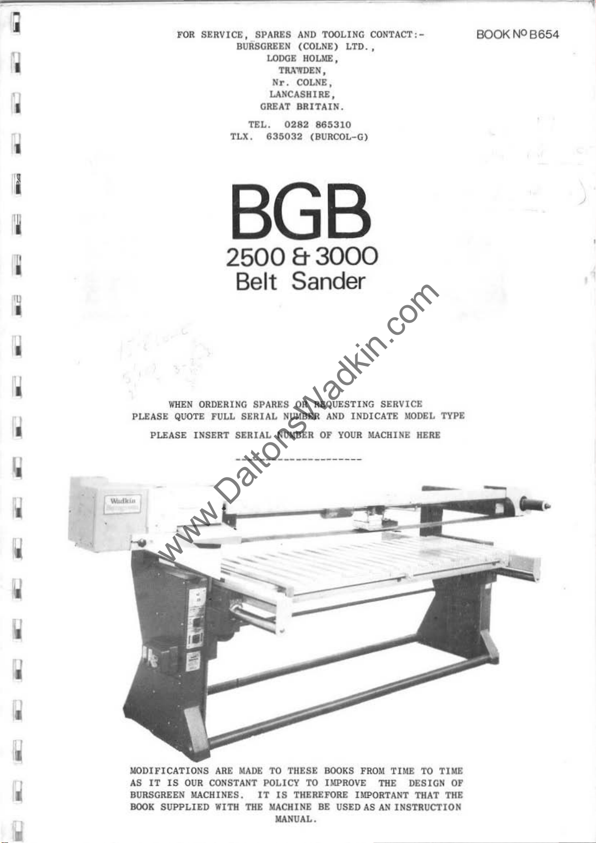
BOOKNOB654
'I
1
I
PL£ASE
PL£ASE
WHEN
ORDERING
QUOTE fULL
INSERT
8GB
2500&3000
Belt Sander
SPARES
SERIAL
SERIAL
OR
REQ~STIHG
HUMBER
NUMBER
AND
OF
INDICATE
YOUR
MACHINE
SERVICE
MODEL
•
TYPE
HERE
• I
•
'J
'.
MODIFICATIONS
AS
IT IS
BURSGREEN
90011
OUR
MACH
SUPPLIED
ARE
MADE
CONSTANT
I IIES. I T IS
.ITH
POLICY
TltE
TO
THESE
TKERUORE
MACHIIIE
MANUAL.
BOOKS fROM TIME
TO
IMPROVE
BE
USED
THE
UIPOftTANT
AS
AN
INST
TO
TIME
DESIGN
THA
T TilE
RUCTION
Of
I
www.DaltonsWadkin.com
www.DaltonsWadkin.com
www.DaltonsWadkin.com
I
I
I
I
I
I
I
I
,
Woodwork
range
ding
M
any
to
WA
believe
table
followi
of
arrange
injuries
use
DKIN LTD
in
1.
2.
3 •
ing
machines
work
ments
the
guards
.•
supp
,
as
a
the
ir
ng
rules
The
operation
req
uirements
tio
ns
correctly
Safe
given
"Saf
(obtainable
and
Onl y
should
methods
ety
as
personnel
HEALTH
SAFETY
can be
of
wh
ich
against
t o
machinists
provided
ly
machinery
result
us
are
1974
in
in
advised
ope
of
e . I t
complied
of
.
All
.
o f
the
Hea
the
from
rate
&
OF
WOODWORKING
dangero
they
of
Use
by
trained
i t .
are
possible
are
or
thorough
is
the
w
the
machine
the
Woodworki
guar
ds should
working
lth
and
of
Her
Majesty'
wadk
capable
caused
to
adjust
designed for
t
user's
ith
only
Safety
Woodworking
i n
Ltd
in
SAFE
us
h
azards.
est
ing. mi
to
ensure
should
ng
shou
s
.
the
TY
if
improperly
,
requires
by
carelessness
them
responsibi
Machines
be u
l d
Work
Machines",
Stationery
safe
MACHINES
use
adequate
correctly.
maximum
n i mi z
safety
conform
sed and
be
Booklet
use
safe
es
lity
at
Regu
adjusted
adopted
Office)
of
a
the
to
No.
machine
d.
or
t y
t o
work:
the
l a-
as
4l ,
failure
which
risks
see
The
wide
safeguar-
they
inevi-
that
,
the
I
I
I
I
I
I
I
I
WAO
...
,
..
, .
5.
",N
.TO'
-
---,~-,-
Befor
the
machine
s hould
All
too
speed
SAFETY
ABOVE
ADVISE:
G"'
H N
e
making
have
ls
se
IS
OUR
RULES
011
THE
~ANE
'
......
should
ceased.
and
lect
ed
WATCHWORD
IN
HIS
SAFE
WO
.
"....
.
"
,'
a d
jus
cutters
must
OWII
USE
R K
S'
tments
be
stopped
must
be
~ppropriate
BUT
THE
INTEREST.
OF
OUR
000
LEICESTER
or
clearing
and all
be
securely
USER
MUST
WE
PRODUCTS
L H
OPf'
COMPLY
WOULD
.
'NGLANO
chips,
movement
for
BE
PLEASE:D
fixed
t he
WITH
T
ELEPHO
,,,
'''
too
THE
TO
..
.....
.... ~ ....
etc.,
and
ling
NE
...
the
o~n
,,,
_
.
..
,,
,~
"."""
,
7
6g11'
"""
..
t"
..
,
I
1
www.DaltonsWadkin.com
www.DaltonsWadkin.com
www.DaltonsWadkin.com
t
I
I
o
I
I
I
I
I
I
I
I
Ellewoe
EHe<u.e . o
Mul"'"",
RI", Ind
So""ln, belt len, .I, (±50mm)
Slndln,
Sandlnl
Slnd l
Slnd i
Th
Ou
N
Shlppln,
n,
", belt pull
rOl'
d~pth
><
u,,><. ion
et
..
~ICh'
..
nd,nl
len'th (BetW""
nd,n, widt
hei,h. und
fall
ubl
e ,,,o,or
belt
w,d, h
belt motOr
bell .p.ee
dl",en,lo
d. l'p<
ey di.m ..
(Double ,wan
out
n.
h (Bet
er
let.
""
.. ndln,
ed
""
Di>m ..
""
!>tl,
nO«)
or
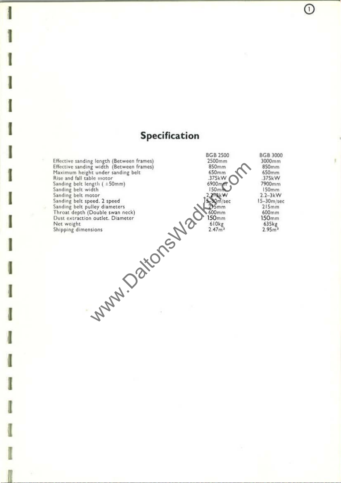
Specification
'rom
..
)
f
..
m
..
)
8GB
2500
""'mm
'
_m
''''''m
,)7S
kW
6'1OO
mm
150mm
}.
I_li<W
1S-30
",/
21S
mm
""
mm
150
mm
610k,
}.47""
,«
00''''''
""'mm
'_m
'_m
.)7SkW
"",,"m
"'mm
U-l
kW
15_)Oml'. (
l lSmm
""m
m
150
mm
6lSk,
].95",'
,
I
I
I
I
I
I
I
r
www.DaltonsWadkin.com
www.DaltonsWadkin.com
www.DaltonsWadkin.com
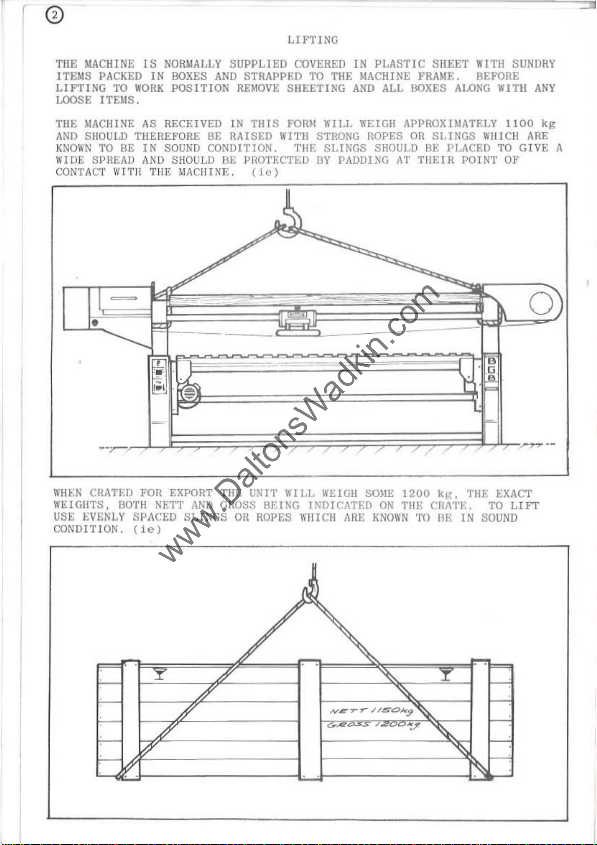
THE
MACHINE
lTEMS
PACKED
LIFTING
LOOSE ITEM
TilE
)!ACIIINE
ANI) SIlOULD THEREFORE BE
KN
OWN
TO BE
WID
E SPltEAO
CONTACT WITH T
TO
IS
IN
WORK
S.
AS
IN
AND
NORMALLY
BOXES
POSITI
RECEIVED IN
SOUND
SHOULD
HE
CONDITION.
MACHINE .
SUPPLIED
AND
STRAPPED
ON
REMO
TillS
RAISED
BE
PROTECTED
Uc)
LU'TI
COVERED
VE SH
FOIUl WIl.L WEIGH APPROXIMATELY 11
lUTE! STRONG ROPES OR
TilE
NG
IN
PLASTI C SHEET WI
TO
THE MACHINE FRAME. BEFORE
EETING
BV
AND
SLfKGS
PADDING
ALL
BOXES
SHOULD BE PI..ACED TO
AT
THEIR
ALOKG
SLINGS
POINT Ot'
TH
SUNDR
WITH
WIIICH ARE
ANY
00
kg
GIVE
o
Y
A
WHEN
W
USI::
CONDITION.
CRATW
EIGHTS,
EVENLY SPACED
FOR EXPORT
30TH
NETT
(ie)
TilE
AND
GIlOSS
SLINGS
UNIT
OH
WILL
BEING
ROPES \I'
WEIGH SOME
I NDICATED
HIel!
ARE
1200
ON
TlU; CHA1'E. TO
KNOWN
TO
k~.
BE
TilE
IN
EXACT
SOUN
LIFT
D
11
www.DaltonsWadkin.com
www.DaltonsWadkin.com
www.DaltonsWadkin.com
1.1
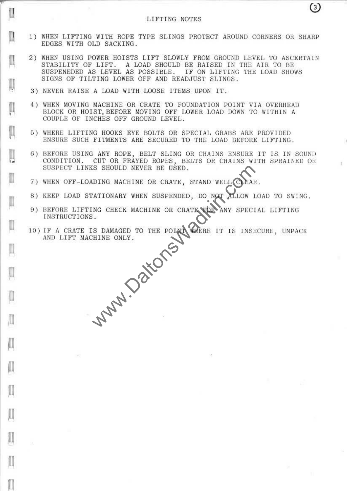
1)
WHEN
EDGES
2)
WHEN
STABILITY
LIFTING
WITH
USING POW
SUSPENEDED
SIGNS
3)
NEVER
1)
WflEN
IHOCK OR
COUPLE OF INCHES
5)
WlmHE
r:NSUH~:
OF
TILTING
llAISE
MOVING
LIFTING
SUCH
WITH
OLD
OF
LIFT.
AS
A LOAD
MACHINE
HorST,
FITMENTS
LIFTING
ROPE
TYPE
SACKING.
ER
HOISTS
LEVEL
LOWER
wr
BEFORE
OFF
HOOKS EYE BOLTS
LIFT
A
LOAD
AS
TH LOOSE
OR CRATE TO
MOVING
GROUND LEVEL.
ARE
SHOULD BE
POSS
IBLE. IF
OFF
AND
SECURED TO
NOTES
SLINGS
SLOWLY
READJUST
ITEMS
FOUNDATION
OFF
LOWER
OR
SP
PROTECT
FROM
GROUND
RAISED
ON
LI F
SLINGS.
UPON
ECIAL
TilE
IT.
LOAD
GRABS ARE
LOIID BEPORE
AROUND
LEVEL
IN
TilE
TING
POINT
nOWN
TilE
VIA
TO
CaHNERS
TO
AIR
TO BE
LOAD
OVERHEAD
WITHIN
PROVIDED
LIFTING
OR
SHARP
ASCERTAIN
SHOWS
A
.
IJ
I .
11
D
o
u
[]
6)
IlEFOIU;
CONDITION
SUSPECT
7)
1I'1lEN
S)
KEEP
9)
U~
:I'OIlE
I NSTltuCTIONS
10)
Jr.
A CHATE I S DAM
AND
USIN
G
ANY
. CUT OR FRAYED
LIN
KS SHOULD NEVER BE
OPF-LOADING
LOAD
LIFT
STATIONARY WHEN
LI
FTING
.
MACHINE ONLY.
ROPE ,
MACHINE
CHECK MACHINE
AGED
BELT SLING
ROPES,
OR
SUSPENDED,
TO THE
OR
CHAINS ENSURE
BELTS
USED.
CRATE , STAND WELL
OR
CRATE FOR
POINT
OR
00
WHERE
CHAINS
NOT ,\LLOI\'
ANY
IT
I S I
IT
WITH
CLEAR.
LOAD
SPF:CIAL
NSECURE,
IS
IN
SOUNIl
SPRAINED
TO SWING.
LIFTING
UNPACK
Oil
/1
I1
11
11
n
11
lnsta
www.DaltonsWadkin.com
www.DaltonsWadkin.com
www.DaltonsWadkin.com
llation.-
Remove
applying
Wiring:_
t he r
efore
supply
POINTS
1
Check
2 -
It
corre
DANAG£
3 •
Check
4
Connect
5
Check
6 CheCk s
two
FAILURE
1
Fuse
2 I s
3
Lock
4
Supply not
The
to
TO
is
olator
a
motor
ct
of
TO
s ha
orf
proteetive
cloth
all
the
NOTE WHEN CONNECTING
voltage,
important
voltage
MOTOR.
maln
lino lea
all
plndle
the
START:-
ve
soaked
and
that
star
connections
swi
or
ter
line
rotates
line
blown
t c h
stOp button
availab
ant
control
is
r e
, o r
phase
tha
t
to
the
fuses
ds
to
le
ad
or
has not
le
i-ru
in
paraffi
gear
quired
isolator
and
the
starter.
are of
correct
are
in
eonnect
have
at
frequency
correct
correct
not
been
(when
ma c
st
to
TO
so
hine.
coa
n o r
have
be
where
POWER
eo
rre
termina
und.
i o
ns.
been
e l
osed
fit
ting
been
done
cable
RUNNING
direetion.
ted)
fr
other
fitted
SUPPLY: -
.
e t c a
ls
fitted
.
om
solvent
wired
i s
to
Is
ON
paeity.
(S
.
has
brigh
used
EE
not
t
parts
.
In
befo
r e
eo
nne
e t
the
.
to
delive
LOW VOLTA
WIRING DIAGRAM).
I f
not
been
GE WILL
re
released.
by
des
main
r t
verse
pat
ch,
s
he
any
1
STOPPAGE
1
OverloadS
If
2
Fuses
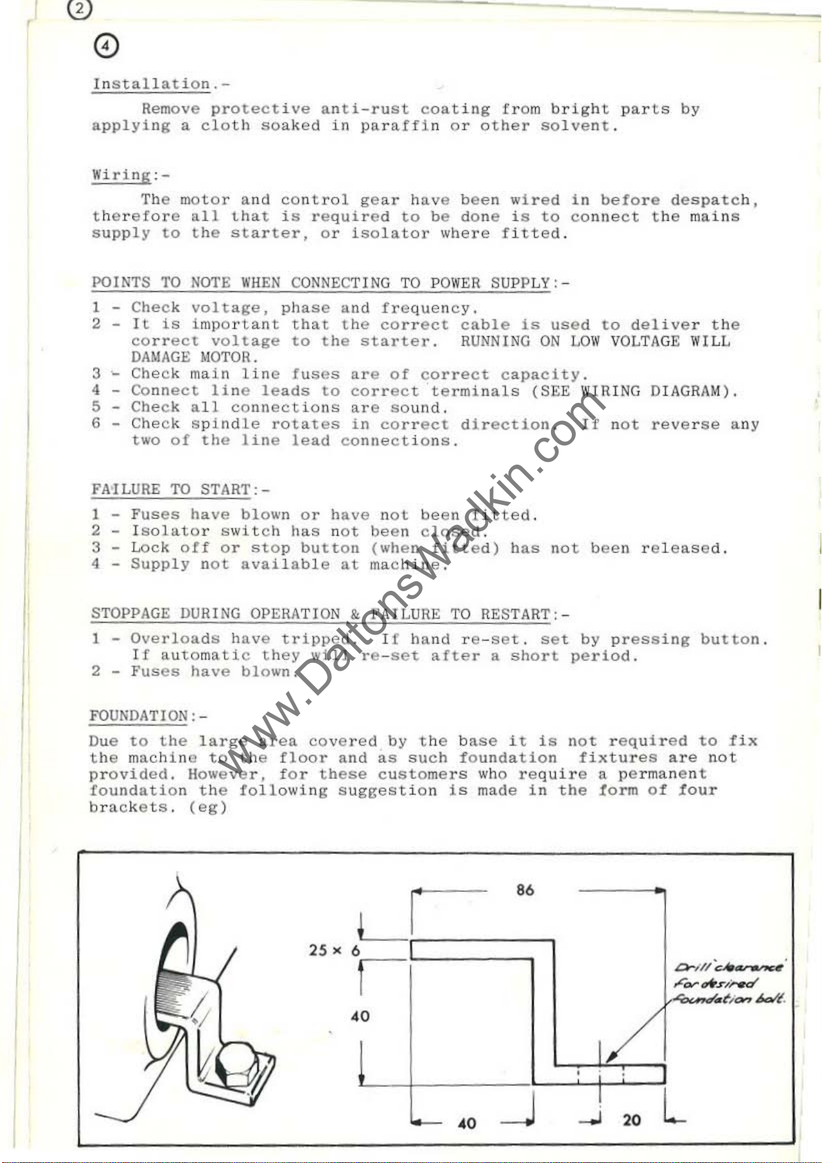
FOUNDATION:
Due
provided.
brackets.
to
the
machin
foundati
DURING
automatic
the
on
have
have
large
e
However,
the
(eg)
to
blown.
the
followi
OPERA
tripped
t h
ey
area
floor
fo r
TlON
covered
ng
&0
will
and
these
sugges
,
".
fAILURE
. I f
re-set
hand
after
by
t he b
as
such
eustomers
ti
o n
LI
I
TO
RESTART:-
r e -set.
a
ase
f o
undation
who require
Is
ma
de
set by pressing
short
it
86
period.
is
not required
fix
in
the
a
form
t ures
permanent
are
of
button.
to
not
lour
Drl//~
...........
.rN-N
~,.
fix
,
.....
4.a/{
1
.
"
'--
,.
~
1/
!
-'
2.
L
11
www.DaltonsWadkin.com
www.DaltonsWadkin.com
www.DaltonsWadkin.com
"
cl
11
11
I!
11
11
11
,.
C"_
'------'.'<;--;--
,
,..
--L-
. J
L-
, I
n-Q,,""-----I--
•
•
.~
r-'
'"
.L
-
CO
0
•
•
"
.-
• •
c
~
..
, J
T
/i
O
"'~"--
,
I
,
,
,
,
-
/"(3)
-
---1-..:::;
r·
.
~
'
0
...
)
'O
"','4'
~
i)
,
,
(
I
•
,
I
'1
I '
..a
-
"cl=
' Y _
It
.-=-
)'
& <
'0'
,,,,,
:;,,0-
,,-/N.-.;
CWl'A • .........-
_""v""
~ky
$,,'-""""'
~
. ,
0.
,
''' .
• •
1
www.DaltonsWadkin.com
www.DaltonsWadkin.com
www.DaltonsWadkin.com
~
0
ABRAS
For
be
machine
BELT DIMENSIONS
8GB 2500
BGB
The
must
REMOVAL,
To
ad
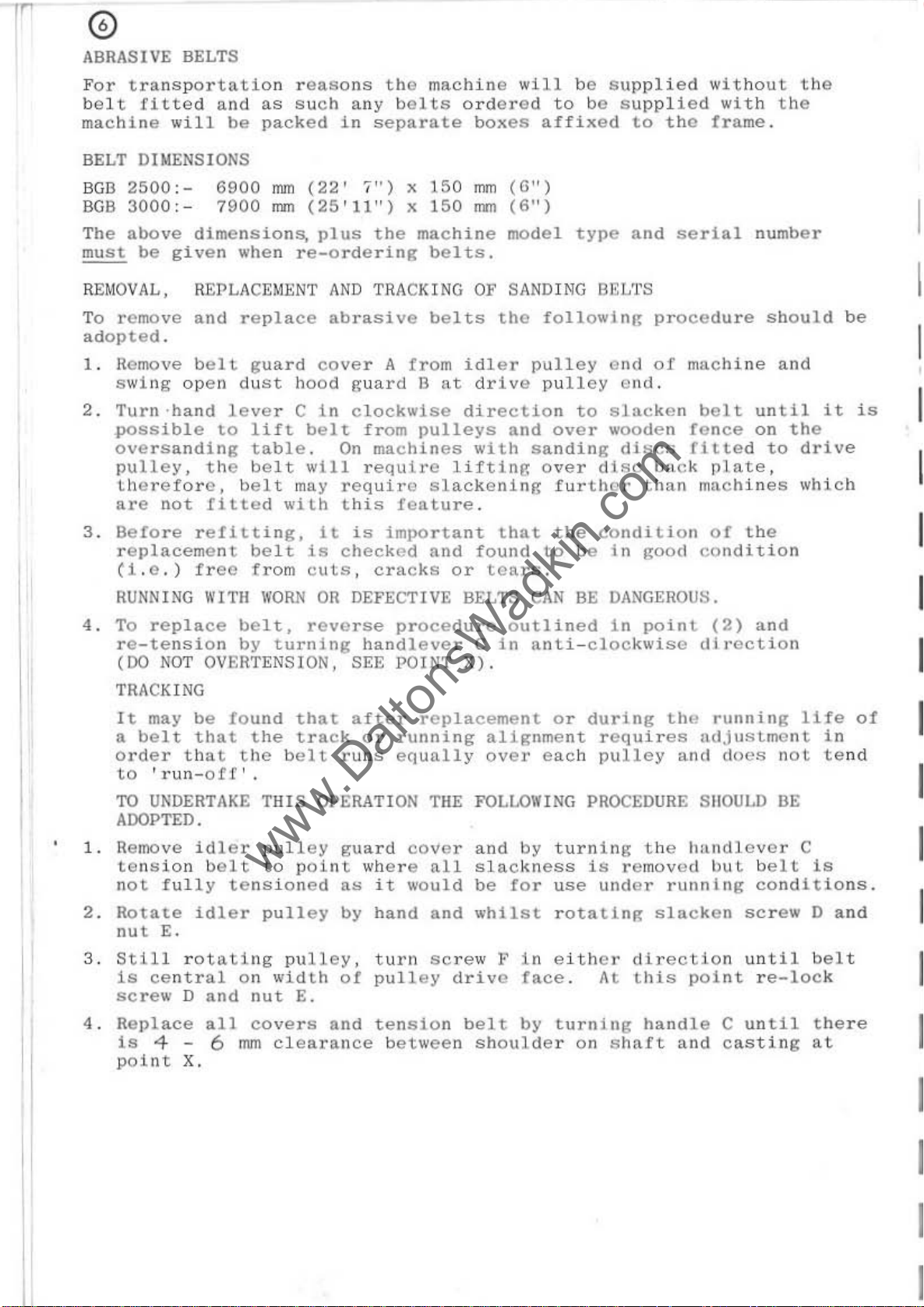
1 . Remove
2.
IVE BELTS
tr
ansp
lt
fitted
will
:-
3000
above
be
:-
given
remove
opted
s w
Turn -hand
possible
oversanding
pulley,
are
.
ing
open
tllerefore,
not
ortatio
and
be
6900
7900
dimensions,
when
REPLACEMENT AND
and
repla
belt
du
lever
to
the
belt
fitted
n r
as
packed
mm
rmI
guard
st
lift
table
bel
t
with
easo
ns
s u
ch
any
in
separate
(22'
(25'11")
plus
I")
the
re-orderin
TRACKING
ce
abrasive
cover
hood
C
may
tn
belt
.
wtll
gu
ard
clockWise
from
On
machines
require
require
this
the
belts
x
x
g
A
featu
trom
machine
ordored
boxes
150
mm
150
mm
machine
belts.
OF
belts
idler
B
at drive
direction
pulleys
with
li
ft
slackeni
re.
will
to
affixed
n
)
(6
(6")
model
SANDING
the
fo
pulley
pulley
and
over
sanding
ing
over
ng
f u
be
sup
plied
be supplied
to
type
llowin
to
rther
and
B~;L'I'S
g
cnd
cn
d.
Slacken
wooden
discs
disc
without
the
trame
serial
procedure
of
machine
be
fence
fitted
back
than
plate,
machines
with
l t
the
the
.
number
should
and
until
on
the
to
drive
which
it
be
is
3.
Before
replacement
(l.e.)
RUNNING WITH
4.
To
replace
re-tension
(DO
NOT
TRACKING
It
may
a
bel t that
order
to
'run-
TO UNDERTAKE
ADOPTED.
1.
Remove
tensio
not
fully
2.
Rota
t e
nut
E.
3.
St
ill
ls
ce
ntral
sc
rew D and
reUt.ting,
beit
fr
ee
from
WORN OR
belt,
by
turning
OVERTENSION,
be
found
the
that
n b
rotat.ing
off
idler
olt
t.ensioned
idler
the
'.
on
nut
belt
THIS
pulley
t o
pulley
width
it
is
culs,
reverse
that
t.rack
OPER
polnt
pulley.
E.
is
important
checked
cracks
DEFECTIVE
hand
SEE
after
or
runs
ATION THE FOLLOWING PROCEDURE SIlOULD BE
guard
where
as
it
by
hand
turn
of
pulley
and
or
pro
ced
lever
POINT
replacement
running
equally
cover
all
would
and
sc
drivo
that
found
toars
BELTS
ure outlined
C
In
X).
alignment
over
and
Slackness
be
whilSt.
rew
}'
the
to
.
CAN
anti-clockwise
Or
each
by
for
use
ln eith
face
conditjon
be
in
good
BE DANGEROUS.
In
point.
during
requires
pulley
turning
i s
rotat.lng
.
removed
under
e r
direct
A~
this
t he
slacken
of
cond;tion
(2)
dl
the
running
running
ndjustment.
and
does
handlever
but.
i o n
pOint
rection
the
and
not
belt
conditio
screw
until
re-lock
life
C
Is
D
belt
in
te
and
of
nd
ns.
I
I
I
I
I
I
I
4 .
Replace
Is
4 6
point
X.
all
covers
mm
clearance
and
tension
between
belt
shoulder
by
turning
on
sh
handle
alt
and
C
cas
until
tin
g
t
here
at
~
 Loading...