


-----
www.DaltonsWadkin.com
www.DaltonsWadkin.com
www.DaltonsWadkin.com
-----<
I
BOOK
NOB556
CIRCULAR
PLEASE INSERT SERIAL
NUMBER OF MACHINE
MODIFICATIONS
AND IT IS IMPORTANT THEREFORE THAT
WITH
THE MACHINE SHOULD
ARE MADE
SAW
TO
THESE BOOKS FROM TIME
ONLY
BE
USEDAS A WORKING MANUAL
BENCH
THE BOOK SENT
TO
TIME
_
www.DaltonsWadkin.com
www.DaltonsWadkin.com
www.DaltonsWadkin.com
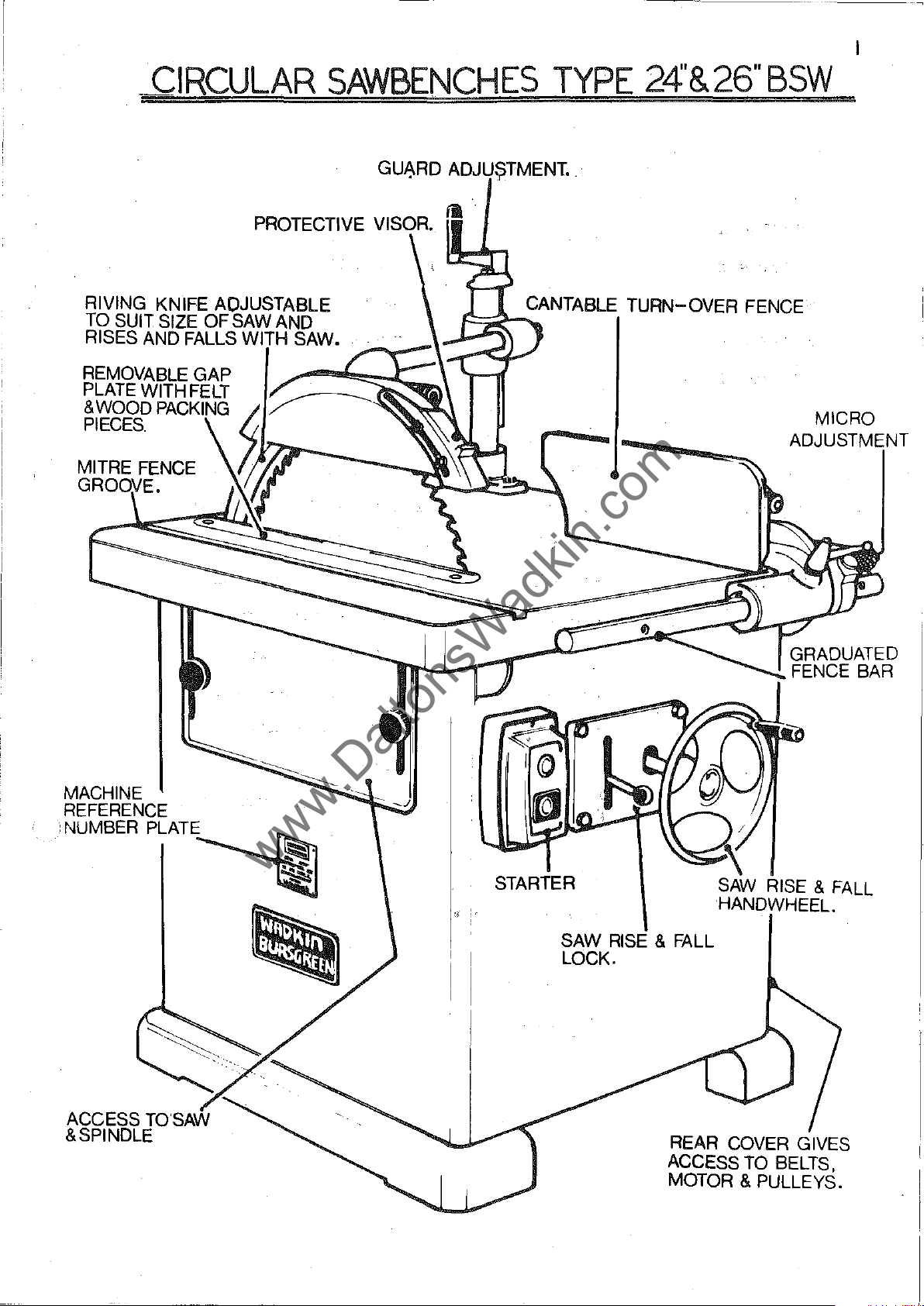
CIRCULAR
SAWBENCHES
TYPE
------
24'&26"BSW
RIVING KNIFE
TO
SUIT SIZE
AND
RISES
FALLS
~'"'--_-C_-:
lAIn
'MCLt:
...
:[I~-1r-JCr:::~~::::~~GRADUATED
..
~~
......
CANTABLE TURN-OVER FENCE
ADJUSTMENT
FENCE
MICRO
BAR
MACHINE
REFERENCE
-.NUMBER
PLATE~
\SI.
......
~
-.
STARTER
SAW
LOCK.
~\
RISE & FALL
REAR
ACCESS
MOTOR
SAW
HANDWHEEl.
RISE
COVER
TO
& PULLEYS.
GIVES
BELTS,
& FALL
2
www.DaltonsWadkin.com
www.DaltonsWadkin.com
www.DaltonsWadkin.com
-------
-------------------------------------
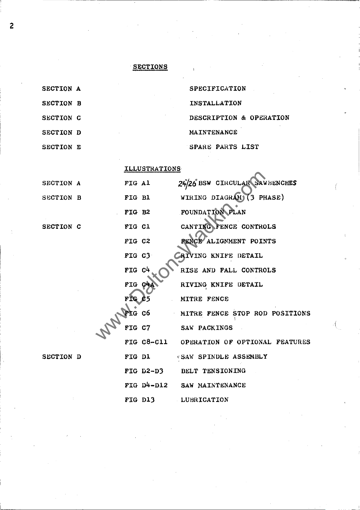
. SECTIONS
SECTION A
SECTION B
SECTION C
SEc'nON
D
SECTION E
SECTION A
S8CTION B
SECTION C
ILLUSTRATIONS
FIG
Al
FIG
Bl
FIG
B2
FIG
Cl
FIG
C2
FIG CJ
SPECIFICATION
INSTALLATION
DESCRIPTION
MAINTENANCE
SPARE
24/26'
WDUNG
BSW
DIAGRAH
PARTS
CDWULAR
FOUNDATION
CANTING
FENCE
FENCE
ALIGNMENT
RIVING KNH'E
&
LIST
(J
PLAN
CONTROLS
DETAIL
OPERATION
SAWHENCHES
PHASE)
POINTS
SECTION
D
FIG
FIG
FIG
FIG
FIG
FIG
FIG
FIG
FIG
FIG
c4
C4A
CS
C6
C7
CS-Cll
Dl
D2-DJ
D4-D12
D1J
RISE
AND
FALL
RIVING KNIFE
"
MITRE
MITRE
SAW
FENCE
FI!;NCE
PACKINGS
OPI!;RATION
,!
SA\{
SPINDLI!;
DI!;LT
SAW
TENSIONING
MAINTENANCE
LUI.lIUCATION
CONTROLS
DETAIL
STOP
!
OF
OPTIONAL
ASSJ!:lolllLY
ROJ)
POSITIONS
,{
FEATURES
-,-
www.DaltonsWadkin.com
www.DaltonsWadkin.com
www.DaltonsWadkin.com
:1
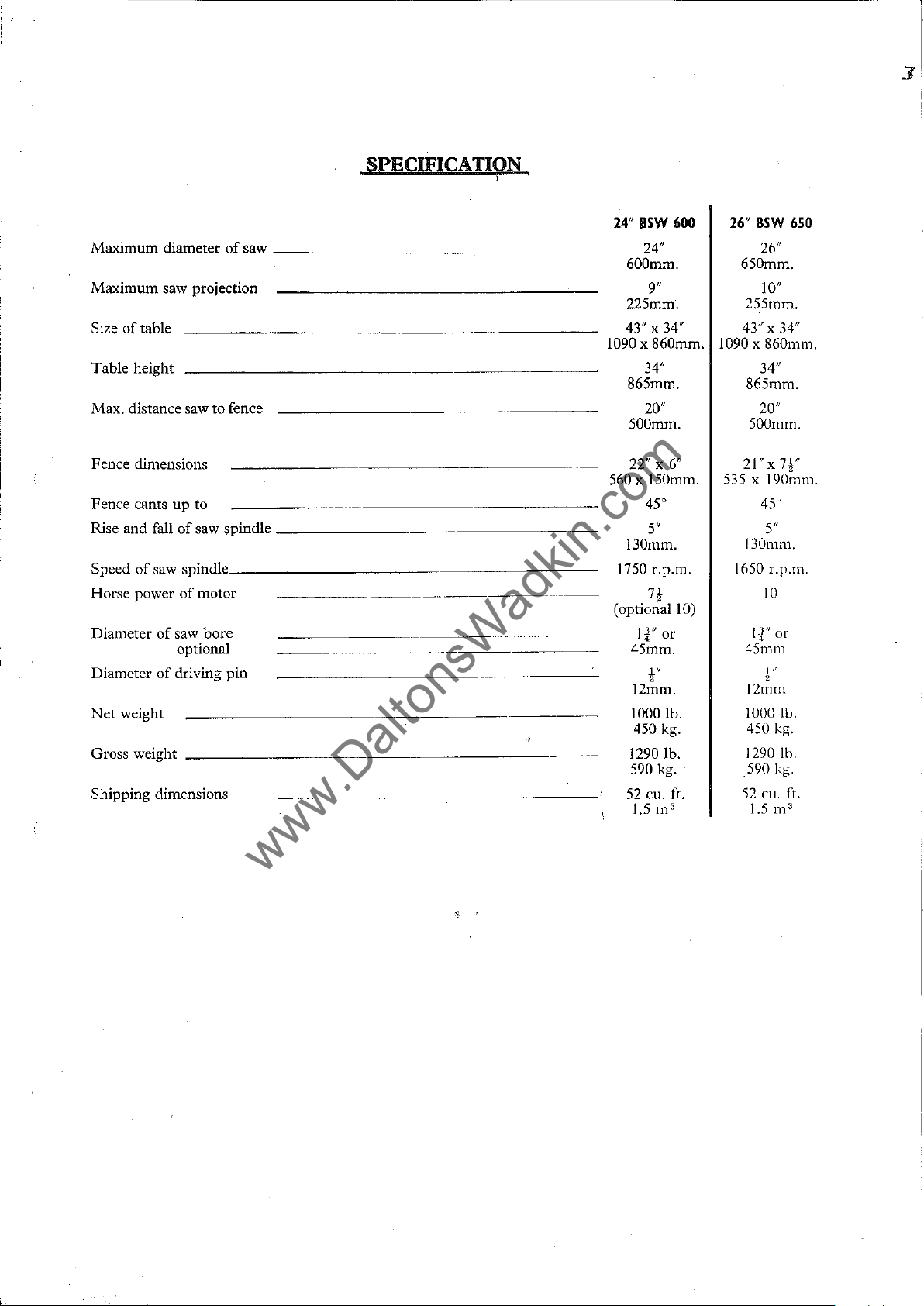
Maximum
diameter
of
saw
Maximum saw projection
Size
of
table
Table
height
Max. distance saw to fence
Fence dimensions
Fence cants
Rise
and
Speed
Horse power
Diameter
Diameter
Net
weight
Gross weight
Shipping
up
fall
of
of
saw spindle
of
of
saw
optional
of
driving
dimensions
to
saw spindle
___________
motor
bore
pin
SPECIFICA
_________________
_________________
~.
________
nON
i
..
_----
.-._--
24"
_
1090
560 x 150mm.
_
~
1750 r.p.m.
(optional
BSW
600
24/1
600mm.
9"
225mm.
43" x 34"
x 860mm.
34"
865mm.
20"
500mm.
22/1
x 6"
45"
5"
130mm.
7!
1
&"
or
45mm.
l"
2
12mm.
1000 lb.
450 kg.
1290 lb.
590 kg.
52
eu. ft.
1.5
m'
1090 x 860mm.
535
10)
26"
BSW
26"
650mm.
10"
255mm.
43" x
34/1
865mm.
20"
500mm.
21"x
x 190mm.
45
130mm.
1650
10
If'
45111111.
~"
12mm.
1000 lb.
450 kg.
1290 lb.
590 kg.
52
eu. ft.
1.5 m
650
34/1
7r'
5"
Lp.m.
or
3

4
www.DaltonsWadkin.com
www.DaltonsWadkin.com
www.DaltonsWadkin.com
SECTION B
,
Installation:
Remove
'applyin~
a
Wiring:-
The
therefore
supply
POINTS
~
-
Check
2 -
It
motor
all
to
the
TO
NOTE
voltage,
is
important
correct
DANAGE
3 -
I, _
5 -
6
Check
Connect
Check
Check
any
main
all
two
-
protective
cloth
that
starter,
voltage
HOTOR.
line
connections
spindle
of
soaked
and
lVHEN
line
leads
rotates
the
anti-rust
in
paraffin
control
is
required
or
gear
isolator
CONNECTING
phasA
that
to
fuses
the
to
and
the
starter.
are
correct
are
in
line
lead
coating
or
have
to
be
been
done
where
TO
POWER
frequency
correct
cable
RUNNING
of
correct
termin"ls
sound.
correct
direction.
connections.
I
from
other
wired
is
fitted.
SUPPLY.
is
capacity.
bright
solvent.
in
to
connect
used
ON
LOW
(SEE
parts
before
to
delivAr
VOLTAGE
by
despatch,
the
mains
WILL
the
WIRING DIAGRA}I).
If
not
reverse
FAILURE
I -
2 -
J -
4 -
TO
Fuses
Isolator
Lock
Supply
have
off
SlOPPAGF; DUll
1 -
Ov',rloads
J f
automatJ.c
2.
-
FU:.ies
have
Foundation:-
The
machine
mounting
floor
cement.
adequate.
and
For
into
rag
(see
START:-
blown
switch
or
stop
~ot
available
ING
OPBRATTON
have
bJown.
concrete,
bolts
mounting
Fig.
ha9
tripped.
they
should
fitted,
B2.)
or
have
not
button
will
6"
on
wood
been
(when
at
mAchl.ne.
&.
FA
1'.'-S8L
be
levelled'
to
after
not
lLUHE
If
i,and
8"
floors
been
closed.
fitted)
TO
re-set,
after
and
square
which
cOBch
fitted.
has
l'(ESTART:-
a
short
bolted
holes
the
holes
bolts
not
set
period.
down
should
will
been
by
pressine:
"hould
released.
firmly.
be
cut
be
be
found
hutton.
For
in
the
run
with
-
www.DaltonsWadkin.com
www.DaltonsWadkin.com
www.DaltonsWadkin.com
-------------------
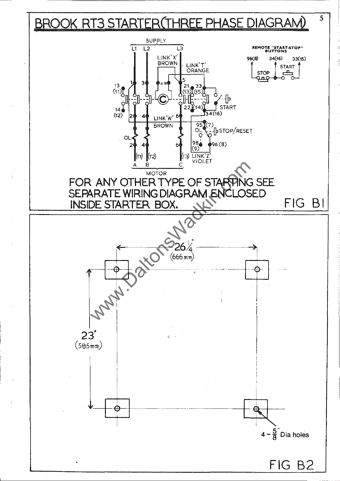
~ROOK
RT3
STARTERCTHREE
,
SUP,PlY
L1
l2
LINK'
X'
BROWN I LlNK'T'
_I
ORANGE
13
).
3
(11)6
~
--U---O-c ---0-
14
~
(12) 2 4 '
Ol.
2 4 6
(Tl)
A B C VIOLET
"-'--..:::...--,.~~
LINK W
BROWN
(r2)
MOTOR
ab
\ 5
21
(13~(j5)~
22
,6
n)
PHASE
33
-----0
14)
34(16)
95,(7)
O~
\--lPSTOP/RESET
98.
(9)
LlNK'ZI
96
DIAGRAM)
REMOTE
9r)
~6o-l
-{P
START
(8)
----
--------------------
5
"START.STOP"
BUTTONS
____
34t~TAR~3r5)
FOR
ANY
OTHER
SEPARATE
INSIDE
~
23"
(S8Smm)
STARTER
0(
TYPE
WIRING
DIAGRAM
BOX.
--
OF
STARTING
ENCLOSED
26~'
(666
mm)
-------
---
~
--------
SEE
~
..
~-
FIG
--
BI
-----------+-I~t
I
5"
4 - 8 Dia holes
FIG
B2
6
www.DaltonsWadkin.com
www.DaltonsWadkin.com
www.DaltonsWadkin.com
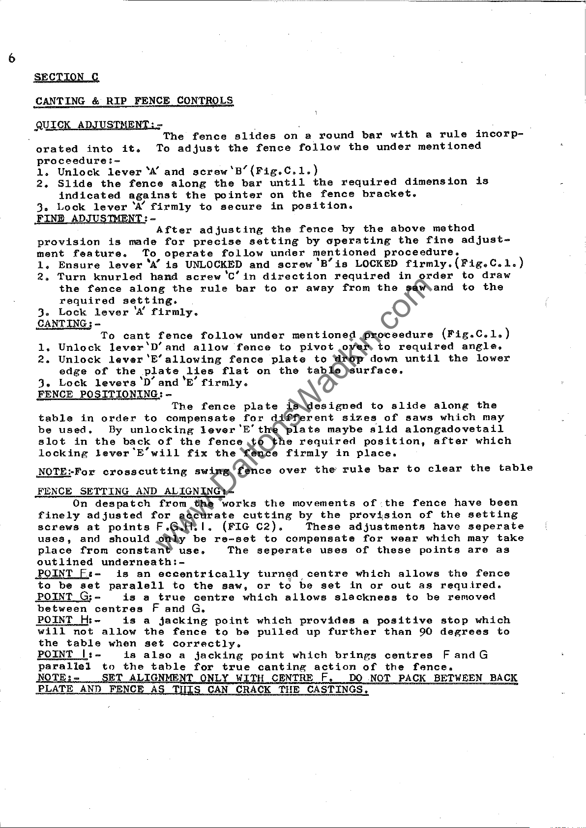
SECTION C
CANTING
.QUICK
orated
proceedure:-
1.
2.
J.
FINE
provision
ment
1.
2.
J.
CANTING:-
1.
2.
J.
FENCE
table
be
slot
locking
ADJUSn!ENT:-
Unlock
Slide
indicated
Lock
ADJUSIMENII-
feature.
Ensure
Turn
the
required
Lock
Unlock
Unlock
edge
Lock
POSITIONING:-
in
used.
in
&
RIP
FENCE
into
fence
it.
lever
the
fence
against
lever
knurled
lever
To
of
levers
order
the
lever'E'will
'A!
is
made
To
lever
along
setting.
'K
cant
lever'D'and
lever'E'allowing
the
\'
By
unlocking
back
The
To
'A:
and
along
firmly
After
for
operate
'A'
is
hand
the
firmly.
fence
plate
D
and
The
to
compensate
of
CONTROLS
fence
adjust
screw'B'(Fig.C.l.)
the
to
adjusting
precise
UNLOCKED
screw'C'in
rule
follow
allow
lies
",
E
firmly.
fence
lever
the
fix
the
the
pointer
secure
follow
fence
flat
fence
the
slides
bar
bar
fence
plate
for
'E'
fence
fence
until
on
in
the
setting
under
and
screw'B'ia
direction
to
under
plate
on
different
the
to
the
on a round
follow
the
the
fence
position.
fence
by
operating
mentioned
or
away
mentioned
to
pivot
to
the
table
is
designed
plate
firmly
maybe
required
bar
the
required
bracket.
by
the
LOCKED
required
from
proceedure
over
drop
in
down
surface.
to
sizes
s'lid
position,
place.
with
under
proceedure.
the
to
of
mentioned
dimension
above
the
firmly.(Fig.C.l.)
in
order
saw
required
until
slide
saws
alongadovetail
a
rule
method
fine
and
(Fig.C.l.)
the
along
which
after
incorp-
is
adjust-
to
draw
to
the
angle.
lower
the
may
which
NOTE:-For
FENCE SETTING
On
finely
screws
uses,
place
outlined
POINT
to
be
POINT
between
POINT H:-
will
the
table
POINT
parallel
NOTE:PLATE
despatch
adjusted
at
and
from
underneath:F&set
G:-
centres
not
allow
1:-
SET
AND
crosscutting
points
should
constant
is
paralell
is
is
when
to
FENCE
AND
ALIGNINGI-
from
for
F.G.H. I.
only
an
eccentrically
to
s
true
F
and
a
jacking
the
fence
set
correctly.
is
also
the
table
ALIGNMENT
AS
TIllS
swing
the
accurate
be
re-set
use.
the
centre
G.
point
to
a
jacking
for
ONLY
CAN
fence
works
cutting
(FIG
The
saw.
which
be
true
WITH
CRACK
over
the
C2).
to
seperate
turned
or
to
which
pulled
point
canting
CENTRE
THE
the'
movements
by
the
These
compensate
uses
centre
be
set
allows
provides
which
slackness
up
further
brings
action
F.
CASTINGS.
rule
bar
of
the
provi,sion
adjustments
for
wear
of
these
which
in
or
out
a
positive
than
centres
of
the
DO
NOT
to
fence
of
which
points
allows
as
to
90
fence.
PACK
clear
have
the
have
the
requ
be
removed
stop
degrees
F
and
BETWEEN
the
table
been
setting
seperate
may
take
are
as
fence
tred.
which
to
G
BACK

7
www.DaltonsWadkin.com
www.DaltonsWadkin.com
www.DaltonsWadkin.com
FIG.Cl
FIGC2
8
www.DaltonsWadkin.com
www.DaltonsWadkin.com
www.DaltonsWadkin.com
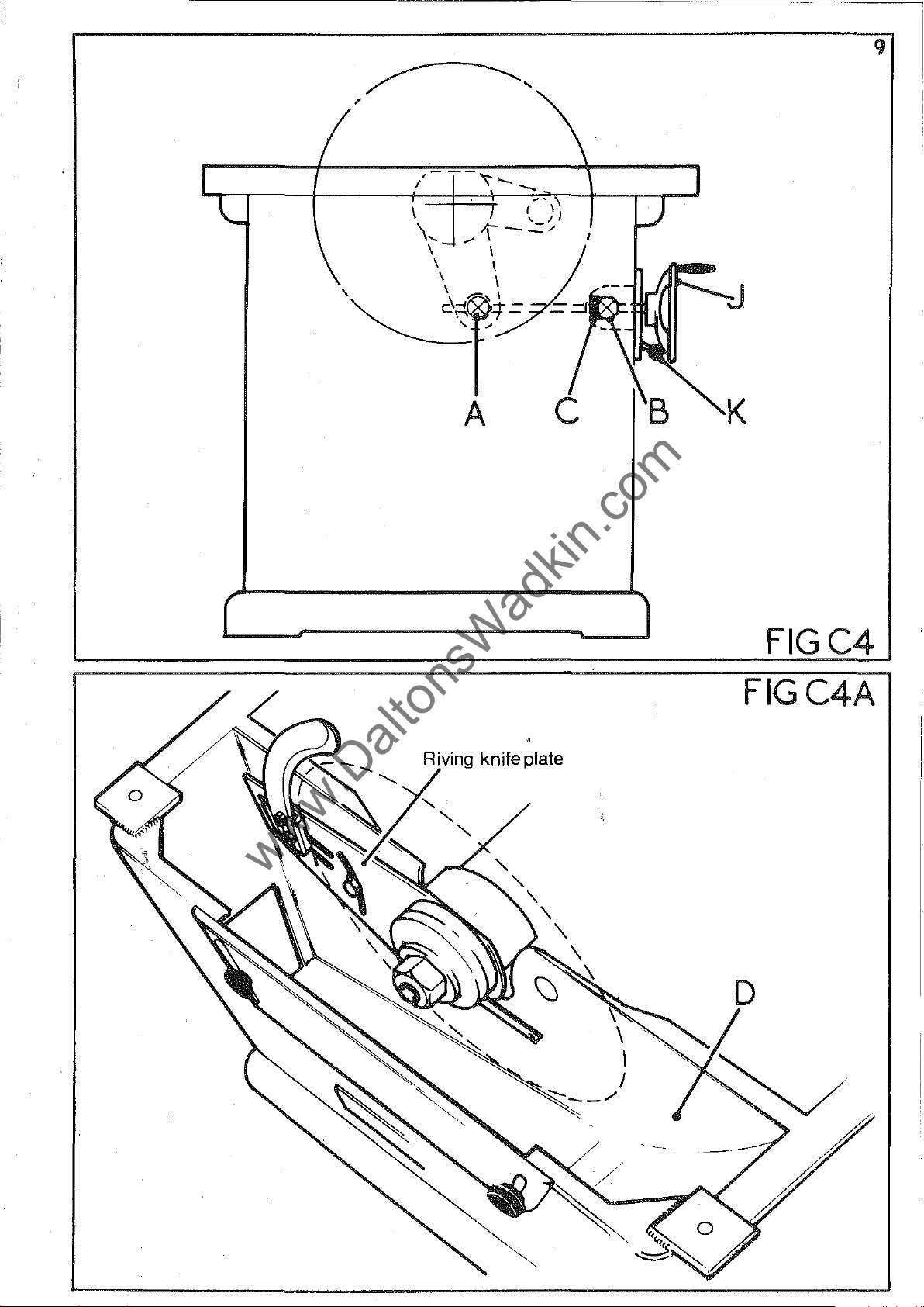
RISE
lo"ered
'A'
varied.
handle
points
race
important
ly
and
AND
FALL
By
turning
between
specification.
It
'K'
is
The
C
A.
is
that
rise
&
fitted
that
B.
the
CONTROLS:-
handwheel
the
maximum
Under.
is
important
locked
and
fall
(FIG
to
the
thrust
C4.)
give
pivots
firmly
handwheel
free
race
'J'
(fig.
and
no
circumstances
after
before
At
the
ro·tation
and
is
screw
oiled
C4
)
the
m1.nimum
operatin~
running
is
handwheel
position
connected
"hen
are
cleaned
accordinl"
the
sa"
should
the
end
in
may
as
rise
saw.
through
of
the
use.
and
to
the
be
r~ised
given
this
and
dimension
fall
pivoted
screw
It
luhricated
maintenance
in
is
or
section
that
a
therefore
lever
yolks
thrust
regular-
schedule.
be
at
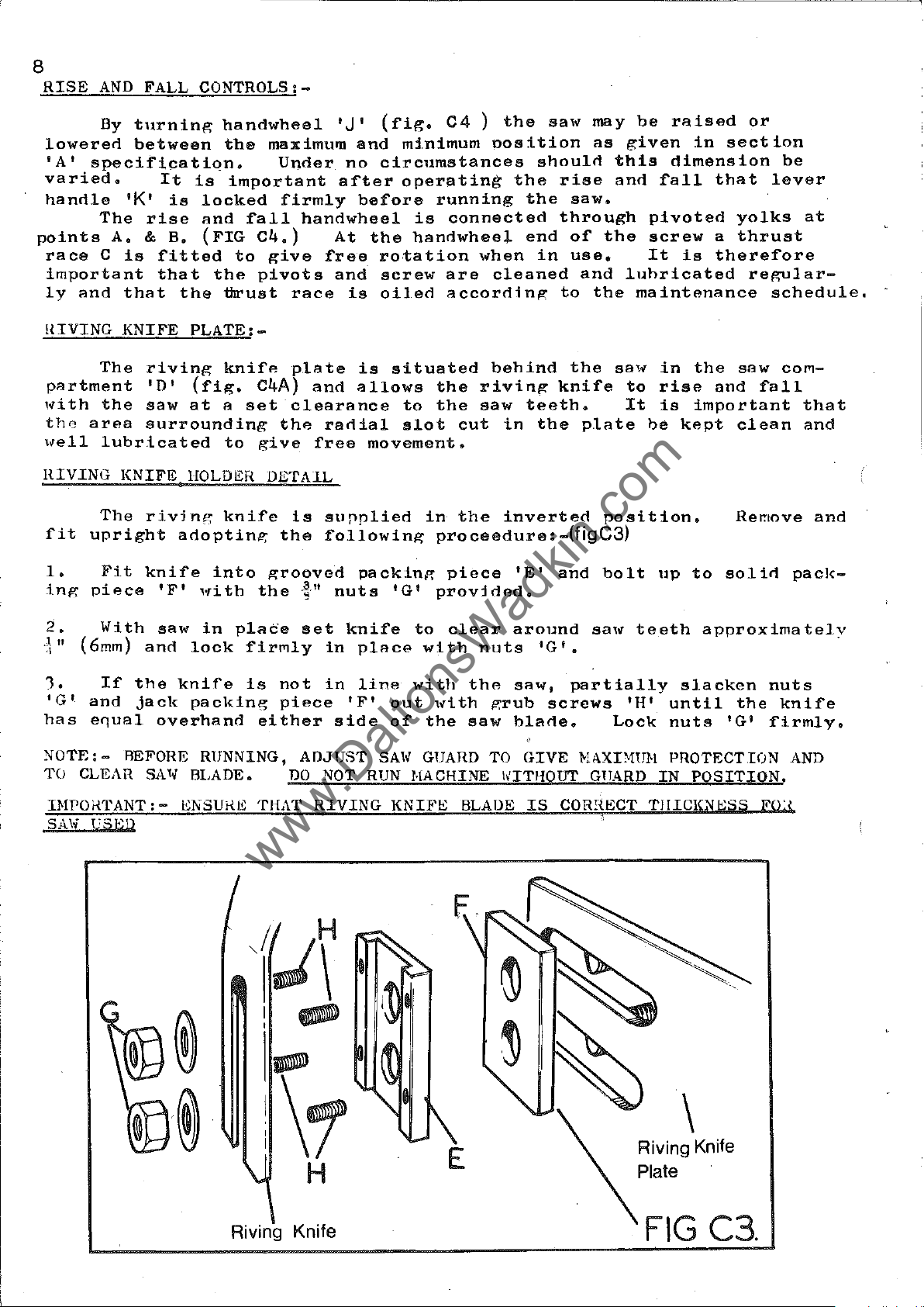
llIVING
p~rtment
with
the
\fell
HIVING
fit
1.
inp:
2.
.1"
.\
1.
'G'
has
NOTE:
TO CLEAR SA1,
KNIFE
The
the
area
lubricated
KNIFE
The
upright
Fit
piece
With
(6mm)
If
the
and
jack
e~u~l
- BEFORE
riving
'D'
saw
surrounding
rivjng
knife
'F'
saw
and
overhand
PLATE:-
knif"
(fig.
at
a
to
HOLD!;;"
knife
adoptinl';
into
with
in
plade
lock
knife
packing
RUNNING,
BLADE.
C4A)
set
the
give
DETAIL
the
grooved
the
firmly
is
not
piece
either
p1~te
and
clearance
radial
free
is
supplied
following
."
nuts
set
knife
in
in
'F'
side
ADJUST
DO
NOT RUN
is
situated
~llows
movement.
pack:ln,,,:
place
line
SAl,
the
to
the
slot
in
proceedure:
'G'
provided.
to
with
with
out
,dth
of
the
GUARD TO
HACHINE
piece
clear
rivinp:
saw
cut
the
nuts
the
saw
behind
teeth.
in
the
inverted
'E'
around
'G'
saw,
p;rub
I>ITHOUT
screws
blade.
GIVE
the
sa'"
knife
plate
position.
-(figC3)
and
bolt
sa"
•
partially
Lock
t<li\XDlUH
GTJARD
in
to
rise
It
is
be
up
teeth
'H'
until
nuts
PROTECTION
IN
the
saw
and
fall
important
kept
slacken
clean
Remove
to
solid
approximatelY
the
'G'
POSITION.
COI'1-
that
and
and
pack-
nuts
knife
firmly.
AND
INPOf{TANT:
SA\!
VSED
-
t;NSUf{~;
THAT
j~\
I.
®
-
.~
1\1
Riving Knife
RIVING
H
KNIFl;;
BLADE
E
IS
CORr{ECT
TJIICIGiESS
\
Riving Knife
Plate
F(U
-,
www.DaltonsWadkin.com
www.DaltonsWadkin.com
www.DaltonsWadkin.com
-
J
A
K
FIGC4
FIGC4A

10
www.DaltonsWadkin.com
www.DaltonsWadkin.com
www.DaltonsWadkin.com
HOUNTING
SAliBLAOES:-
When
1.
2.
position.
J.
spindle.
4.
Check
especiAlly
Rpindle
the
').
fore
..!l..
NOTE:-
HUE TO THE
Isolate
Remove
Remove
Select
saw
Check
replacing
THPO.tTANT: -ENSURE
(ELECTRICS
the
checking
bore
IF
mounting
machine
table
spindle
blarle
hlade
where
and
that
the
L
Tlm
SAW
RUNNING
saws
insert
nut
required
is
in
it
will
that
pin
hole
the
saw
flange
SPINDLE
FL.\)IIGE
the
undermentioned
and
raise
(left
good
he
the
teeth
OR
OUT-OF-TRUE.
hand
depending
condition
gripped
fac~
centres
and
SA',[
of
point
locking
il.UNS
~'ACES
proceedure
the
saw
spindlp
thread)
on
and
by
the
hack
fit
correctly
towards
up
IN
COHRECT ClIRI,;CTION, f(8Fj<.;n
ARE NOT CLlCA'I
type
the
And
free
SAW
saw
the
f'irmly
of
from
ho"sing
front
work
dirt.
flange.
flange
onto
front
with
TillS
shoulrl
saw
which
is
those
of
the
CAN
be
into
flAnge
is
sawdust
Hount
clean
on
the
mAchine
spindle
TO
CAUSE
fOllowed:-
the
f'rom
to
be
and
saw
on
And
thAt
the
flange.
nut.
SrXTIlJN
VIJlHATION
top
done.
,?,Um.
the
be-
MITHE
which
setting,
quick
the
mitre
(!'iI':.
rods
~nd
(fig.
FENCE
The
mitre
should
and
setting
Accurate
CS.)
The
hy
the
'0'
anrl
C6.)
(;C.1..p....Jt5)_(EXTRA.)
fence
rods
fence
be
a
positive
at
repetitive
are
two
slide
kept
firmly
clamps
is
clean.
900 and
held
the
fitted
stop
in
in
'D!
rorls
0
45
to
any
cutting
the
To
into
into
A
scale
'A'
is
the
position.
can
fence
adjust
the
the
groovp
is
provirled
incorporaterl
saw.
be
ohtAined
with
position
the
the
The
plastic
thumbscrews
stop
req'Jired
provided
to
in
the
by
USA
ro<ls
on
inrlicate
seale
hAnd'"heel
of
'C'
slAcken
~s
illustrHted
the
the
and
seo",
accurate
to
give
'B'
stop
the
C1A"'PS
t"hle,
locks
rods
stop
'C'
in

C
www.DaltonsWadkin.com
www.DaltonsWadkin.com
www.DaltonsWadkin.com
FIGC5
I1
MITRE
SLOT
----.
-
~'----'.
I
!
FIGC6
-
~
STOP
RODS

12
www.DaltonsWadkin.com
www.DaltonsWadkin.com
www.DaltonsWadkin.com
SAli
PACKING.
It
it
is
not
out-of-true
and
gap
packing
consequent
The
wood
retains
the
f'elt
strips
OPPOSITE.
he
amount
ouces
at
mouthpiece
underside
in
It
rene"eo,
The
heat
every
is
usual
intenoed
saws.
plate
must
loss
arrangement
the
f'elt
position.
close
)
shoulrl
ano
rrovision
of'
lubricating
and
opportunity,
is
not
of'
the
he
burning
to
provioe
th"t
The
to
steady
be
tight
of
tension
of'
a
packinl':
the
At
saw
noted
sho111(1
of'
this
idea
of'
the
length
tRhle
the
p;ap
thnt
not
the
oil,
whilst
the
a
the
"s
in
saw
extending
pieces
and
rear
and
he
felt
which
felt
sa'"
packing
of
fitting
saw,
this
the
packing's
in
to
of
provide
after
"110,,eo
inserts
not
runninp,'.
pieces
blade
but
"ill
blaoe.
place.
the
thA
some
with
be
used
pi-.ckinp,'
it
generate
beyono
front
g"p
a
p;uioe
to
allow
only
are
some
as
should
are
time,
in
the
Also
of'
plAte
for
fall
application
cleans
It
is
1uhricaterl.
form
"
R"uioe
piecAs
he
heat,
such
depth
wood
the
anrl
the
the
packinll's
into
the
therefore
noted
a
Il'ap
table
saw.
b"o
saw,
of
packing,
for
into
that
resulting
way
thRt
of
the
strips
plate
si.milar
(SEE
will
conrlition.
of' a s",,,11
hut
important
buckleo
the
table
the
in
"
saw
secured
support
nIAGHilHS
need
"Iso
but
or
a
hard-
teeth
to
the
wood
to
rethat,
NOTE:-
REPLACENENT LENGTHS OF
FELT
l'~7/'l6"
x
6"
.

Saw
www.DaltonsWadkin.com
www.DaltonsWadkin.com
www.DaltonsWadkin.com
~
I
-cr-
1---
I(~"'"
I
I
~L
I
I
I
I
I
I
lEE>
L_
FIGC7
Gap
plate
Saw
SECTION
~A
Saw
Felt
13
Table
~--
I
Hardw{)j
C)("~e=====:::::::=t==+~:f-.II
I
a:(B
LL-I-4~.~
I I
I
I I
Felt·~+======t=l~~
----,
I
I
®:a'
:
I
I
Gap Mouth
plate piece
... : ...
::+
/h/
" / 11-
EBI
.F
--17/Ndl.._I~ardwood
- - mouthpiece
",
/ I
X
Screw
SECTION
~aa~
Saw
/
-
'i1
/
I
"-
SECTION~
~CC
""...,....,..,.,.'-.r
l
If
I
Table
.-.
'1.""
J<
--1,/
,"
/
,/

14.
www.DaltonsWadkin.com
www.DaltonsWadkin.com
www.DaltonsWadkin.com
B
PILLAIl
hanrlle
unlock
th"
correct
knit'e,
until
to
clear
the
guard
SAW
GUARD
'B'
(FIG
lever
unlock
correctly
timber
cover
FIG
To
re
CB)
'C'
anrl
position.
lever
positioned.
by
will
CB
ise
and
lower
To
position
slirle
'E'
approximately
hinge
To
and
the
centralize
up
slide
I.hen
and
the
the
guard
guard
in
over
gua
rd,
guard
pillar
the
back
operating,
(Jmm)
to
unlock
on
'0'
guard
or
To
reve"l
centre
until
to
forwarc1
ensure
gain
blade.
lever
clear
visor
access
witll
th"
aJong
'A'
the
guard
saw
'G'
to
anrl
and
bar
turn
saw,
is
riving
is
saw,
in
'F'
set
FIG
SPINOLE BRAKE:-
situated
brake
and
To
excessive
pillar
.md
placing
the
a
llow
of
C
11
next
pad
by
is
spring-loaded
tension
slackness
at
the
tensionccable
brake
rivet
the
heads -are
brake
special
to
the
means
the
cable,
spindle
pad
pad
to
pulley.(FIGC11)
This
rise
ot'
to
is
as
mentioned
it
is
below
wear
device
a
cable
relieve
turn
to
end
important
down
and
the
be
and
the
is
operated
fall
'B'
leading
tension
knurled
removed,
pull
above
that
surface
to
rivets
handwheel.
",hen
nut
unlock
cable
with
new
of
as
through,
knurled
the
this
from
from
hand
'C'
rivets
the
pad
the
It
the
pressure
on
grub
re-lock
screw.
are
material.
will
brake
is
connected
operating
the
lever.
screw
used
score
lever
is
grub
l¥hen
and
the
'A'
lever,
reljeved.
'D'
screw
that
Do
surt'ace
to
the
Where
on
the
re-
not

15.
www.DaltonsWadkin.com
www.DaltonsWadkin.com
www.DaltonsWadkin.com
SECTION
MAINTENANCE
"c"

16
www.DaltonsWadkin.com
www.DaltonsWadkin.com
www.DaltonsWadkin.com
SECTION
During
to
replace
proceedure
1.
2.
).
4.
5.
6.
ISOLATF:
REHOVE G<\P
MACHINE.
SLACKEN AN]) RBHOVE
TENSION
WIND SAIl'
REMOVE COUNTERSUNK SCRE1; ANI)
IN
RE}iOYE KEY
RENOVB
HEHO
D.
-
the
worn
follow
PULLEY
CIRCLIP
YE
DUSTCAP
HAINTENANCE:-
operating
or
damaged'pnrts
the
undermention<~d
?-lAClllNE
PLATE,
STUDS
CARRIAGE
'C'
'D'
ELECTRICALLY
.\FTER
AND
AND
'F'
'H'.
life
SAl,
V-ROPES
PAC1CING HOTOR UT'
INTO
RENOVE.
DISTANCE
AND
of
AND
HIDWAY
HOTOH
the
(i.e.
BEFOaE
SA1~
SPDlDLE
FRON
POSITION.
I,ASHSR
PIF:CE
T8NSION
sawbench
ba,ll
instr\lctions.
PULLEYS
'E'.
races.)
ATTENPTING
FRONT
,\S
'A t AND
HRACKgT
it
may
be
fO\ln<1
To
un<1ertake
(SEE
AN·)
1\]\1)
HF:~IOVE
SH01{N
SLACKEN GRUB SCRE1,rS
'G'
FIG
ANY
WORK.
H~;AH
IN
COVERS FRON
TURNnUCKLB
(FIG
ANIl lJNSCHE1,
D
necessary
this
1.)
1'111':
AND
D.2.)
'H'
AND
8.
'.'.
10.
11.
A
re
*"
th e ri
for
tion.
WORKING
AND
UNSCfmw
To
thoroughly
the
SA
HEHClVE
t
L'
•
PLACE
SHA~'T
FRO}!
ING
TITH.OTlGIl
It
THE
FHON
re-assemble,
shoul<1
vi
nIT
motion
AT
T!lE
IV
FLANGE
SAt,
FLANGE
RIVING
A I{oODEN
THROUGH
HOPSING
TilE
'HTH
cleanerl
a.1so
kni
f'e
pla
of
FRONT
'J'.
KNIFE
DRIFT
Tlm
HOIJSING.
\HTIl
SHAFT
HA}IHER
reverse
out.
be
note<1
te
should
the
plate
OF
THg
'K'
(L.Jl.Tl{Hr;AD.)
PLATE*ANl)
ON
THE
TIlE
SA"
AND
RE-INSEaT
ANT)
mUI'''!'
above
thAt
only
"nrl
SAW
SPINDU~t
LINK,
PULU;Y
TIY
D01NG
EN')
TO
the·,
not
R8AIUNG
SHAFT
IlENOvg
proceedure
two
be t iroh t enprl
to
clamp
AND
EN])
locknuts
HENClVE NUT
UNSCHEW
OF
TlIE
TlIIS
ON
INTO
THB
eneurinr:
or
TilE
HOrSING
PllLLSY
pnour:;h
lock
A~,1l
SPI:-iDU:
Sf'INi)LE
IT.
..
on
T)llIVE
EW)
all
thp.
to
the
'I'
(L.H.THHEAD)
im)'IOVE
ANIl
KNUCl:ING
orie;inal
radi"l
provirle
plate
nUST
f)[(IVE
\HLL
THIS
nEAHING
in
CAP
'I'll"
!';hEHGE
BEAR-
SPINDU:
•
pFtrts
slot
a
flU
po"i-
in
id
e

17
www.DaltonsWadkin.com
www.DaltonsWadkin.com
www.DaltonsWadkin.com
'1
GJ
o

18
www.DaltonsWadkin.com
www.DaltonsWadkin.com
www.DaltonsWadkin.com
--------~~-----------
BELT
saw
maximum
correct
the
tioned
distance
the
of
applying
tion
defle
REPLACING
buckle
wards
TENSION:-
spindle
"running
proceedure.
By
belts.
the
pulleys
is
ct
ion.)
To
and
retension
is
efficiency
belt
turning
not
replace
of
the
a
force
greater
BELTS:-
thll"
tension
To
On
by
means
in"
turnbllckle
pullevs
achieve
(FIG
at
belts,
relievi.ng
as
all
mAchines
and
is
period.
(SEE
DJ.)
right
than
given
of'
four
life.of
maintained
FIG.
'A'
can
be
the
correct
and
angles
1/64"
decrease
tension
above.
the
ALPHA
these
To
tension
D.2.)
linking
increased
adjust
per
pulley
drive
at
and
inch
on
from
500,
helts,
all
the
the
tension,
with
central
of
centre
the
type
times
tension
to
the
span
belts
the
main
"V"
it
is
from
belts
provide
measure
turnbuckle
Along
-
(e.g.
distance
for
motorto
Belts.
important
new,
follow
studs,
greater
the
the
belt,
2J"
by
their
To
that
especially
the
the
tension
centre
until,
span
screwing
removal.
the
ensure
the
undermen-
centre
distance
whilst
the
deflec-
=
2'3/6h"
in
on
turn-
Aft
er-
POINTS
1.
2.
J.
ALWA
REPLACE
ALtrAYS RF:PLACE
4.
5.
6.
TO
NOTE
YS
HAINTAIN
\VOIt"
ENSURE
DO
IMPLEHENTS
ENSFRE
RUST
PUlLEYS
NOT
PRISE
PULLEY GHOOVES
OR
BURRS 1.11lCIl ARE
WHEN
HAINTAINING
COimECT
BELTS
11'OHN
ARE CORl{ECTLY
BELTS OVER
AS
THIS
BELT
BELT
WITH SAl'lE
OH
D.\HAGED BELTS
PULU~YS
CA?
DAMAGE
AND
BELTS
PHES~~NT.
DRIVES:-
TENSION.
TYPE
ALIGl\ED.
AS
\HTH
BF;LTS.
AHE
SPECIFIED.
IHHEDIATELY.
SCHEl,
CLE:AN
DRIVERS
,
AND
OR OTHER SHARP
REMOVE
ANY
OIL,
GREASl')

~--+--t---A
www.DaltonsWadkin.com
www.DaltonsWadkin.com
www.DaltonsWadkin.com
19
Method of packing up
motor for removal of
tension screws as
outlined in sectionDl
I
FORCE
FIG
FIG
DEFLECTION
1f640F
PER
AN
INCH
INCH
OFSPAN
D2
D3

20
www.DaltonsWadkin.com
www.DaltonsWadkin.com
www.DaltonsWadkin.com
SAW
MAINTENANCE:-
Efficient
the
saw
of
the
to
ensure
HANGING:-
'Ranl':inF,
fourth
sive
whilst
teeth
SAW
in
sqll"re
equal
gullet
rounrleo.
:bevels
their
original
machine.
block
filao
SI1ARPENING:-
Do
a
vice
number
original
spindle,
spindle.
straight
or
fifth
in
running.
not
as
faces
of
the
Wi.th
as
in
profile,
operation
and
The
cutting.
down'
a
li~htly
run
shown
ara
of
saw
(FIG.
sha
woooen
The
a
saw
required
strokes
in
cross
shape
it
shoulo
rpen
in
D7.)
the
to
sew
ing.
holoer
saw
remove
when
(FIG
the
cut
and
i"
of
a
saw
flanges
must
he
done
shoulo
blunt.
05.)
(FIG
with
necessary
same
saws
In
the
a
the
gullets
circular
also
on
To
range
(FIG
then
the
ranging
With
D6.)
flat
manner,
points
course
to
being
run
a
D4.)
To
file.
become
saw
at
new
down.
lightly
be
removed
re-sharpen
rip
Sharpen
taking
are
of
grind
depends
perfectly
the
saw
feed
marks.
saw
At
care
needed
repeated
shallow.
the
correct
or
al':ainst
anrl
teeth,
hy
the
saw
on
true
square
any
saw
a
square-edged
the
by
hand,
chisel
".ivine:
same
to
keep
with
filing,
on
hack
a
running
to
the
peripheral
after
the
saw
tops
e"ch
time,
To
saw-sharpening
holrl
eoges
tooth
the
anrl
saws
restore
of
file
gullet
front
speed
the
abra-
teeth
the
the
lose
the
of
axis
saw
anrl
an
the
well
SETTING:-
The
body
spt'
in
side
a
seen
being
in
indicates
that
&
so
(Le.)
(FIG
or
piece
in
cut,
1,e
(FIG
For
the
D12.)
a,"ount
there
DS)
else
of
timber
(FIG.
hut
CAn
DID)
the
hand
number
is
the
For
the
D9)
supply
This
amount
setting,
3"
14
Bore
of
freedom
teeth
saw
where
is
of
set
are
good
will
The
usually
a
small
device
of
saws
shOUld
from
bent
sawing,
run
the
a[,lOunt
010"
machine
wi
set
small
used
be
friction.
alternately
this
to
result
of
to
11
a
by
micrometer
devi.ces
does
sufficient
amount
one
side.
shoulo
set
015"
for
ccept
can
not
Saw
be
varies
(.3mm:
precisely
saws
dial.
be
warrant
to
teeth
to
the
of
set
To
a
according
.4mmJ
up
to
supplieo
a
give
rip,-ht
shoulo
check
small,
setting
36,"
machine
clearance
are
generally
or
he
the
even
to
saws
in
diameter.
where
(SI':E
to
the
'spring
left
set,
triangle,
the
it
as
shown
erll",l
~'IGs.Dll
at
cut
t.imher
as
shown
and
is
felt
into
saw
each
as
16 Bore
STANDARD
PIN HOLE CENTRES
SAW AND
~"
8
CNT
9"

FIGD4
www.DaltonsWadkin.com
www.DaltonsWadkin.com
www.DaltonsWadkin.com
FIGD5
FIGD6
Clearance
angle15°
Hook1
RIP SAW
FIGD7
Clearance
angle 43
CROSSCUT SAW
0
===i~1~~l===d~~s=e:~~5~f:~~
Saw cut Set
Area of tooth
shown shaded
FIGD8
set-over
---....-""
~.-=~~
l .. ...::
.~
FIGD9
FIGDII
FIGDIO
FIG
10
I I
_18--"'_,..,j1
DI2
11..-.
___
15
2~0

FIG Dl3
www.DaltonsWadkin.com
www.DaltonsWadkin.com
www.DaltonsWadkin.com
LUBRICATION
DIAGRAM
RI
Cl
7"_:::::::=-i~'"
_-..-----r-r-'I.-.
I
1111
1-
l
,.,.
A~
__
,
v~\""
---\=:
i~,~
......
-
\--
i
I
\ 1
\
-1
....
-
"\-I.
L\,
1I.'"
.......
__
~t~
\"
_ -,-
-
~
A-
B-Oil
C-"THRUST
D-Grease-two
Oil
and
weekly.
each end per year.
"
clean weekly.
RAC(oil
weekly.
shots
A
A
A
10
A
/},
<?--'--
/
/./}/
,:,(
J ,
\ I
',-
__
.........
\
/9'--D
Dust Outlet
8x5
I L i
I -
I l
I I
I I
I I
__
I

----
www.DaltonsWadkin.com
www.DaltonsWadkin.com
www.DaltonsWadkin.com
23
SECTION
SPARE
PARTS
11
E
LISTS
"

24
www.DaltonsWadkin.com
www.DaltonsWadkin.com
www.DaltonsWadkin.com
REF.
NO.
1
2
3
4
5
6
7
~8
10
11
12
13
14
15
16
17
PLEASE
9
18
19
20
21
22
23
24
25
26
27
28
29
30
MW
75~.
BSW
750.
BSw75Z.
BSX
12.
BSW
751.
BSW
137.
BSW
27.
STATE
BZG
70.
MAIN
1
1
1
1
2
1
1
1
VOLTAGE,
1
2
2
8
4
4
2
2
2
2
?
8
2
2
1
2
2
2
1
2
3
2
PHASE,
BASE
&
FREQUENCY.
ASSEMBLY
MAIN
TABLE
GAP
SPINDLE
BASE
FRCNT
BASE
BROOK
WADKIN
REAR
FRONT
No. 10
~"
~"
~"
i"
211
i"
PLASTIC
~"
il:"
il:"
SPRING
~"
DZUS
t"
DZUS
f'
2BA
3/16"
BASE.
PLATE.
FEET.
COVER.
RT 3 STARTER.
WOOD
WOCD
WHIT
WASHERS.
DIA X 1"
WHIT
WHIT
WASHERS.
WHIT
WHIT
WASHERS.
WHIT
AJW6-55
EX'l'ERNAL
s6-275
DIA
X
WHI'f
DESCRIPTION.
PULLEY
COVER.
BURSGREEN
SAW
WOODSCREWS.
X 1i"
X
i"
X 1i"
HANDWHEELS
X 1"
X
~"
GUARD
NUTS.
BRASS
~"LOlJG
COVER.
PACKINGS.
SAW
PACKINGS.
LONG
LONG
LONG
LONG
LONG
LONG
CLIP.
WWG
CIRCLIP.
SPRING.
RIVETS.
HOUND
X
t."
LONG
NAMEPLATE.
DOWELS.
HEXAGON
HEXAGON
)
)
HEXAGON
RCUND
STUDS.
REF:
NUT.
HEAD
COUNTERSUNK
BOLTS.
HEAD
6687/B.
BOLTS.
BOLTS.
SCRE'IS.
SCRE'IS.
SCREW;
WHEN
ORDERING
MACHINE.
SPARE
PARTS
PLEASE
QUOTE
PART
NUMBER
AND
SERIAL
NUMBER
OF

~"
www.DaltonsWadkin.com
www.DaltonsWadkin.com
www.DaltonsWadkin.com
___
------.c
••
..
-~
?---2
4
i
'3
, \
~
~~--
~
C
C
,
(,'
\;l
, .
~
c"
0
:[
1----
~
-8
\
20
5

26
www.DaltonsWadkin.com
www.DaltonsWadkin.com
www.DaltonsWadkin.com
40
41
42
43
44
45
46
47
48
49
50
51
52
53
54
55
56
57
58
59
60
61
SAW
BSW759.
BSW
80.
1
BS1
760.
BSW
5.
BSS
57.
'BSW
519.
BSW
761.
BSX
?/A.
BSW
61/A.
BSX
19
SPINDLE
llQ..
ASSEMBLY
£IT.
1
1
1
1
1
1
2
1
2
1
2
1
1
1
1
1
1
1
1
1
1
2
1il:"
WHIT
FRON'r
SAW
DRIVING
REAR
HOUSING
5/16"
5/16"
5/16"
SKF
6308
RBAR
5/16"
HOTCH
2;!-"
EXTERNAL
PULLEY
SPINDLE
5/16"
5/16"
;!-"
WHIT
SCREI,
SPINDLB
~"
SQUARE
KEY.
SPINDLE.
KINGFISHER
FORM
SAIl
SAl,
FLANGE.
FRONT
WHIT
WHIT
WHIT
SINGLE
HOUSING
WHIT
TENSION
DISTANCE
PULLEY.
WHIT
WHIT X 1il:"
X 1"
•
PULLEY
DESCRIPTION.
L.H. 7
FLANGE.
PEG.
DUiiTCAP.
X
3f;"
LOCKNUTS.
X
3t:"
DUSTCAP.
COUNTERSUNK
BRACKET'.
CICLIP.
X 1"
COUNTERSUNK 1 SELF
WASHERS.
X 1i"
UO
2
LONG
GREASE
T.P./
LONG
STUD.
ROW
J3BAHINGS.
PIECE.
LONG
ALLEN
LONG
SINGLE
STUD.
SCHBVlS
ALLEN
CUPS.
NUT.
i"
GRUB
GRUB
LOK
ROUND
LONG.
SCREW.
SCREW.
1
11'JD
'NOTE:
PART
WHEN
OF
MACHINE.
PART
NO.
ORDERING
NO.
HEF:
BSW
519 IS
92.
SPI\RIC
PAHTS
ALSO
USED
PLICASE
ON
i/.UOTE
RISE
PART
AND
FALL
r;NHBER
UNIT
AND
SEE
SERIAL
PIIGE29
NUHBBR

40
www.DaltonsWadkin.com
www.DaltonsWadkin.com
www.DaltonsWadkin.com
41
42
4344
~
~
61
".,.
• 0
\-\\\
\!
J
! /
/ /
...
rn:
!!Ill
!!IIIII
)))
f!j/
11
!Ill i III
1111
1111
!iI!iiilllll
47 46
~
JO~~3
~~
.~
-.le
\-51
6/
~
1t55
~
56
~
60

"*
www.DaltonsWadkin.com
www.DaltonsWadkin.com
www.DaltonsWadkin.com
See
add!
6:
1011$
10
clrauuinq
28.
SAW
70
71
72
73
74
75
76
77
71l
79
80
81
82
83
84
85
86
87
88
89
90
91
92
93
94
95
6
(9
97
98
99
100
101
102
103
104
105
10(,
1\~r7
108
10~
11
111
112
11)
114
115
116
117
(SPZ
118
119
120
121
122
123
124
125
126
127
121l
129
130
131
132
133
134
135
136
137
138
1270)-ALPHA
BSW
9.
S
125/A
6698/A
MW
10
5296/3
MW
35
MW
1 9
MW
37
BSW
34
SKF
0.6
BSW
41)
BSW
33
- - - 1
MOTOR
- _ _ 3 i!:"
MW
BSS
MW1')O---1--24"BSW--fIOTOR
MX
MW7S6
BSW
BSW
BSW
BSW
BSW
IlSW
BSW
BS\>!
BSW
BSW
llSW
BSW
BSW
BSX
BSW
BSX
MW
MW
,BSli/
MW
M\v
MW
BSW
MW
BROOK
(
11
SHAFT
519
2')
SjA
43
7/A
7
134
42
31
142
147
135
500
4
50
51
49/A
is'
754/A
2J
29
28
159
38
18
20
39
62
MOTOR
STANDARD
!I
RISE&FALL
1
1
2
4
9
1
1
1
1 1i!:i. DIA X i"
1
1
4
2
2
3 i!:"
2
1
1
1
KEY
(PLlo:ASE
1
1
2
1
1-
1
1
1
2
2
2
2
4
3
h
?
2 i"
2 SPINDLE
1
1
1
2
2
1
1
1 j)EtlSION
4-
1
1 SUPPORT PLATE
1 SUPPORT PLATE LINK
1 SUPPORT PLATE LINK
1 SPINDLE
1 RIVING KNIFE SUPPORT PLATE.
1
4
1 RIVING KNIFE
1 RIVING KNIFE
2
3
1
1
1
1
1
1
1
11
~UOTE
26"
BSW
24"BSW
26"BSW
7.5
10
HP
ASSEMBLY
9"
DIA
ALLUMINIUM
RISE
& FALL INDICATOR PLATE.
t"
DIA
BRASS
t"
,IHIT
X 1i!:"
i"
WASHlo:RS.
HANDWHEEL
i"
BORE X 2i"
RISE & FAIL
RISE & FAIL
LOCKING
~"
EXTERNAL
RISE
RISE
WHIT
3/16"
THRUST
TH1<UST
RISE
& FALL
~"
I/D
MACHINE & MOTOR
WHIT
MOTOH
2~"
EXTERNAL
5/16"
SAW
RISE
""
t"
DIA
RISE
& FALL
MOTOR
~"
WHIT X 11"
MOTO?
MUTOR
M01'OR
5/16"
i"
\IHIT NUTS.
r"
WASHERS.
2"
WHIT X 1"
WHIT
RISE & FAIL
~"
WHIT
RISlo:
& FALL
~"
WHIT
~"
\/lIlT
fIOTOR
11
"SPACESAVER" VEE-ROPlo:G.
SAW
SPINDLlo: HOUSING.
STANDARD
3/16"
i"
WHIT
fi"
WHIT
RISE
& 'FALL
SPINDLb
~"
I'IASHER.
Jl"
SPECIAL
LOCKING
RISE & FAIL
LINK
PIVOT STUD.
D132S
FHAME,AITERNATIVE
SPINDLE.
LINK.
& FALL
& FALL SCREII COLLARS.
X
~"
DIA X 1i!:"
RAGE.
RACE
X
~"
X
1."
TENSION BRACKrJr.
X
11!:"
AND
PULLEY?-5HP (STANDARD)
EXTlo:RNAL
PIVOT SHAFT.
PIVOT BLOCKS.
PIVO~'
PIVOT
WHIT
X
X
~"
HOUCiING
U:FT
LEF"r
LOCKNUTS.
TENSION
11 11
nUT.
HOUSING
RIVING KNIFE •
\IllIT X
X
1~"
LOCKNUTS.
HOUSING
SLOTTlo:D
LINK NUT.
R1SE &
RIVlo:TS.
LONG
Hlo:XAGON
PLASTIC
BEARING BRACKET.
WHIT
LOCK
CIRCLIPS
LOCK
LONG
LONG
SHROUD.
SCRlo:,1
OlD
X if"
HP,~
LOllG
CIRCLIP.
LONG
WHIT
FAIL
10
,0 HP(STANDARD).
CIRCLIP
LOCK
LINK.
LONG
BLOCKS.
SHAFT
i"
LONG
LONG
LONG
PIVOT
SCREW
HAND,
SCRr;W'LOCK
HAND
SCREW.
LINK.
PIVOT SHAFT.
~"
LONG
HOLDER.
HOLDER
LONG
LOCK
COLLAR.
LINK.
LOCK
SCREW.
HANDLE.
BOR;;
PLASTIC BALL.
HANDLE
LINK
GRUB
PIVOT.
- - - - - - - - •
COUNTI>R!iUNK
SCREW.
STUDS.
COLLARS.
HEXAGON
IXlG
NUT.
THREAD
THREAD
PIN.
PIN
COACH
WASHER.
SHAFT.
TYPE
PINS.
SCR1'WS.
GROOVELOCK
LONG
GRUB
TYPE
CHUB
POINT
SHA"FT
LOCKNUT.
COLLAR.
LOCKNUTS.
(KNURLED).
GHUB
PACKING
BOLTS.
10
HP)
FAIL
HANDLE.
BOLTS.
1300.
OILITE
SCREIIS.
SCREWS.
11
10·0
1400.
SCR);IIS.
KOLTS.
GRUB
CULLARS.
SCREvIS.
PHCE.
DOWELS.
BUSH.
HP.
SCHEWS

29
www.DaltonsWadkin.com
www.DaltonsWadkin.com
www.DaltonsWadkin.com
ft
105
@\
~~
74
123
-=n-
122~
()
125
10
~129
~
119
1&
133
131
0
I~O
132
0
0
8~
ad.
c;:m
ak
~I

30
www.DaltonsWadkin.com
www.DaltonsWadkin.com
www.DaltonsWadkin.com
REF.
NO.
60
0
161
162
163
164
165
166
167
168
169
170
171
172
173
174
175
176
177
178
179
180
181
182
183
184
185
186
187
188
189
190
191
CANTING
PART
NO.
BSS
40
BSX
10
BSW
8 1
BSW
14
BSW
83
BSW
66
BSW
65
BSW
16
BSW
17 1
BSW
57/A
BSW
123 1
BSW
58 1
BSW
526 1
BSW
63
BSW
57
BSW
12
BSW
56
BSS
81l
lJQ..
OFF
1
3
3
2
1
1
1
1
1
1
1
1
1
1
1
1
1
1
1
1
1
1
1
1
1
1
1
1
FENCE
I
FRONT
FRONT
~"
DOVETAIL
BACK
1."
t"
t"
TURNOVER
i"
FENCE
FENCE
5/16"
5/16"
FENCE
i"
FENCE
~1iWHIT
3/16
BRASS
t"
i"
FINE
THUMB
FINE
FINE
BRASS
t"
t"
TURNOVER
RULE
IMPERIAL/METHIC
i"
ASSEMBLY.
DESCRIPTION.
FENCE
FENCE
WHIT X 1."
FENCL
WHIT
WASHER.
WHIT
WHIT
PIVOT
PIVOT
WHIT
WHIT
CANTING
EXTERNAL
LINK
11
WHIT
LOCKING
,/HIT
EXTERNAL
ADJUSTMENT
SCREW.
ADJUSTMENT
ADJUSTMENT
LOCKING
WASHER.
WHIT
POINTER.
WHIT X 11."
PLATE.
PLATE.
LONG
BOLT.
PLATL.
X
~"
LONG
LEVER
BRACKET
LOCKNUTS.
LEVER
X 2"
LEVER
BRACKET.
LOCK
SCREW.
SCREW
SCREW
X
t"
LONG
LOCKNUT.
LINK.
CIRCLIP.
PIVOT
X
PIN.
LOCK
t"
LONG
PAD.
LONG
CIRCLIP.
SCREW
BiiACKET.
SCREW.
PAD.
LOCK
RULE
LONG
24
" )
26"
CHEBSE
GRUB
HANDLE.
(ECCENTRIC).
(TRUE).
GRUB
HANDLE.
GRUB
STUD.
HANDLE.
BAR
ALLEN
BSW·
BSW
HEAD
SCRE'I.
SCREW.
SCREIJ.
COLLAH.
SCREWS.
.
SCRElvS.
NOTE:-
WHEN
OHDERING
SERIAL
SPARE
NUMBER
OF'
PARTS
THE
MACHINE.
PLEASE
QUOTE
PART
NUMBER
AND
 Loading...