

Page 1
3.
/
..‘_ 2,. ., ‘S!
-=
;
,.
+s
,.
/I
”
‘.,: ,,., : 8,. //
i
:
,:-./I
‘j
..:,
‘:, .:,::
‘.”
::: ..q
.”
).
‘.
;L,
./
.:.
INFORMATION AND OPERATING
MANUAL
vwia
9 DECODING COMPUTER
DIGITAL
CORPORATION
Page 2

Page 3

9
DECODING
COMPUTER
INFORMATION
OPERATING
MANUAL
&
Page 4

SOFTWARE LICENSE
IMPORTANT! THIS AGREEMENT SETS FORTH LICENSE TERMS AND CONDITIONS FOR THE
DigiMaster SOFTWARE.
The DigiMaster software is copyrighted and patented. It is the proprietary property of Wadia Digital
Corp of River Falls, Wisconsin.
Title to the Licensed Software is not transferred to the Customer. Customer is granted a nonexclusive
license to use the Licensed Software on a single Decoding Computer basis. The Licensed Software
cannot be shared among multiple Decoding Computers. Each Decoding Computer must have Its own
separately Licensed Software.
Customer may copy the Licensed Software, in whole or in part, only for backup and archival
purposes. Each copy shall include in readable format any and all confidential, proprietary and
copyright notices or markings contained on the original provided by Wadia Digital Corp..
At Wadia Digital Corp’s sole discretion, Wadia Digital shall provide Customer with updates of the
Licensed Software. Wadia Digital retains the right to provide the Licensed Software updates for a fee.
The customer may refuse to accept such Licensed Software updates.
Page 5

CAUTION
TO REDUCE THE RISK OF FIRE OR ELECTRICAL SHOCK, DO NOT EXPOSE THIS PRODUCT TO
RAIN OR MOISTURE.
TO REDUCE THE RISK OF ELECTRICAL SHOCK, DO NOT REMOVE THE PRODUCT’S COVER.
THERE ARE NO USER SERVICEABLE PARTS INSIDE. REFER SERVICING TO QUALIFIED
PERSONNEL.
NOTICE
This equipment generates and uses radio frequency energy and if not installed and used properly, that is,
in strict accordance with the manufacturer’s instructions, may cause interference to radio and television
reception. It has been type tested and found to comply with the limits for Class B computing devices in
accordance with the specifications in Subpart J of Part 15 of FCC Rules, which are designed to provide
reasonable protection against such interference in residential installation. However, there is no guarantee
that interference will not occur in a particular installation. If this product does cause interference to radio
or television reception, which can be determined by turning the equipment on and off, the user is
encouraged to try to correct the interference by one or more of the following measures:
l Reorient the receiving antenna of the radio or television.
l Relocate the Decoding Computer with respect to the radio or television.
l Move the Decoding Computer away from the radio or television.
l Plug the Decoding Computer into a different outlet so that the Decoding
Computer and radio or television are on different branch circuits.
If necessary, the user should consult the dealer or an experienced radio / television technician for
additional suggestions. The user may find the following booklet, prepared by the Federal
Communications Commission, helpful:
“How to Identify and Resolve Radio
-
TV Interference Problems”
This booklet is available from the US Government Printing Office, Washington DC 20402. Stock No. 004-
000-00345-4.
CAUTION
Use of all controls, adjustment or performance of procedures, other than specified herein, may result in
hazardous radiation exposure.
Page 6

Page 7

Table of Contents
IMPORTANT SAFETYINSTRUCTIONS..
.....................................
.7
FRONT
PANEL..
............................................................................
.8
FRONT
PANEL CONTROLS..
.......................................................
.9
REMOTECONTROL
...................................................................
.12
REAR
PANELS
............................................................................
.14
UNPACKING..
..............................................................................
.16
SET-UP
ANDINSTALLATION
....................................................
.16
AC
POWERCONNECTION
........................................................
.17
POWER-UP RESET
.....
................................................................
.17
CARE
AND
MAINTENANCE..
.....................................................
.17
SERVICE
...
....................................................................................
18
BATTERIES
.................................................................................
.18
WARRANTY.
................................................................................
18
SPECIFICATIONS
.......................................................................
.19
Page 8

Our inspiration,
Wadia F. Moses
at age 35.
T
hank you for choosing the Wadia 9
Decoding Computer. Manufactured under
strict quality control standards, the Wadia 9 is
a superb example of state-of -the-art digital
technology We encourage you to read this
manual thoroughly and to carefully follow all
safety and operating instructions, used
properly, this product will provide you with
years of musical enjoyment.
6
Page 9

Wadia 9
DECODING COMPUTER
IMPORTANT SAFETY INSTRUCTIONS
To get the best performance from your Wadia 9 Decoding Computer and for your own
safety, please read and follow these important safety instructions.
1) Before operating the Wadia 9 Decoding Computer please read all operating and safety
instructions.
2) Keep all operating and safety instructions for future reference.
3) Always heed all warnings and cautions on the product and in the Owner’s Manual.
4) Always follow all instructions for the operation and use of the Wadia 9 Decoding
Computer.
5) Never use the Wadia 9 Decoding Computer near water.
6) Never place the Wadia 9 Decoding Computer near heat sources such as radiators,
fireplaces, stoves, or other appliances that produce heat. Avoid placing the Wadia 9
Decoding Computer where it will be subject to direct sunlight or low temperatures.
7) The Wadia 9 Decoding Computer should only be connected to a power supply as directed
on the rear panel.
8) This product is equipped with a three prong AC mains power cord which includes an earth
ground connection. To prevent shock hazard, all three connectors must always be used.
If your electrical outlets will not accept this type of plug, an adaptor may be purchased. If
an adaptor is necessary, be sure it is an approved type and that it is used properly,
supplying an earth ground. If you are not sure of the integrity of your home’s electrical
system, contact a licensed electrician for assistance.
9)
AC extension cords are not recommended for use with this product. If an extension cord
must be used, be sure that it is an approved type and has sufficient current carrying
capacity to power this product.
7
Page 10
Wadia 9 DECODING COMPUTER
FRONT PANELS
INPUT
1 NO DATA
WADIA
9 DECODING COMPUTER:
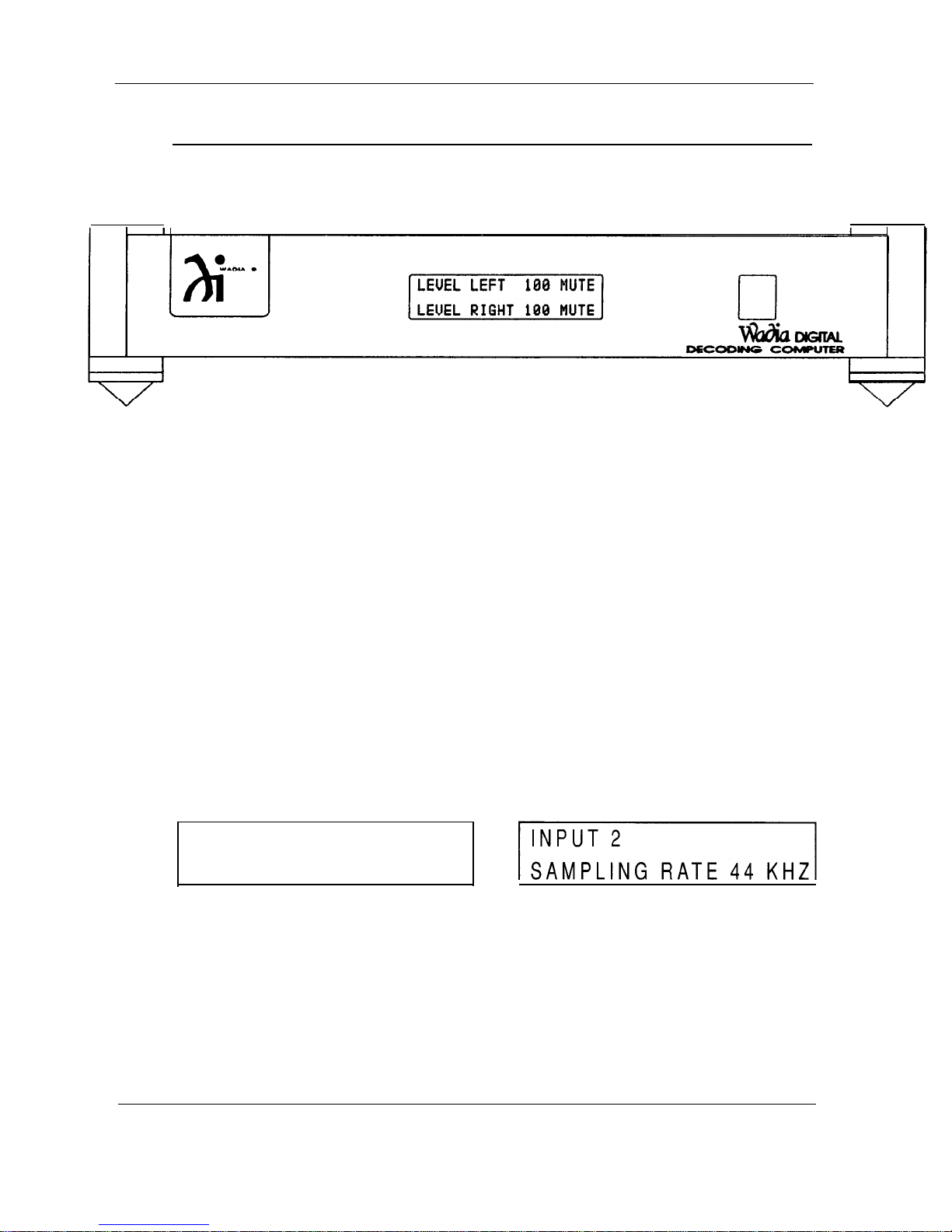
The front panel of the Wadia 9 Decoding Computer is simple and elegant, with only a single
information window, with three individual screens, to indicate the status of the unit. All
functions are accessed through the remote control.
When the digital power supply umbilical cord is connected to the Wadia 9, the display
window will illuminate. If no digital source is connected to Input 1, the information window will
provide the information, INPUT 1, NO DATA.
As mentioned above, the information window has three individual screens, which indicate the
status of the unit.
The first screen indicates the Input selected and the Sampling Rate of the digital source
connected to that input.
8
Page 11
Wadia 9
INPUT: The Wadia 9 Decoding Computer has 3 Glass Optical digital inputs. The input that is
selected through the remote control will be indicated in the information window. Again, if no
source is connected to the input, then NO DATA will also appear. If a digital source is
connected to the input selected, the information window will indicate the sampling rate of the
source.
DECODING COMPUTER
SAMPLING RATE: 32
kHz,
44
kHz,
and 48
kHz.
These three designations correspond to
the sampling rates of the three consumer digital audio formats. When a digital source that is
connected to one of the inputs of the Wadia 9 Decoding Computer is received and
recognized by the Wadia 9, and the sampling rate is locked onto by the Wadia 9, the
appropriate sampling rate will illuminate.
Digital radio broadcasts are typically in the 32
format (indicated on the display as 44
kHz
format. Recently introduced consumer digital recording formats are likely to be in the 32
kHz
format, although some may be at the higher sampling rates. The Wadia 17 Analog to
kHz
Digital converter, for example, can operate at the 48
output, when connected to the Wadia 9 Decoding Computer would illuminate the 48
kHz
format, Compact Disc is in the 44.1
kHz
due to space limitations), and DAT is in the 48
kHz
sampling rate. As a result, its
kHz
sampling rate display.
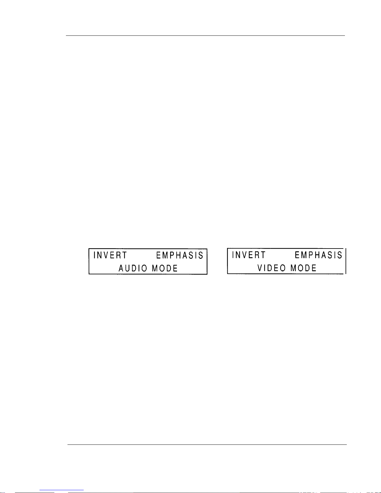
The second screen
indicates
whether the signal has been inverted (INVERT), whether the
source has been emphasized (EMPHASIS), and the Signal Quality of the digital signal
entering the Wadia 9 from a digital source (INPUT SIGNAL LEVEL
1,
for example). The
second screen also indicates when the Time Base Correction circuit has been employed.
INVERT: Indicates digital inversion (plus becomes minus, and minus becomes plus) has
been accessed through the remote control. As there are no standards for correct polarity,
some discs (and even certain songs within a disc) will sound better (tighter bass, more
distinct image) when the signal is digitally inverted.
EMPHASIS: Some discs have been encoded with an equalization process called emphasis.
While giving “better” measurements, these discs always sound worse than they would had
this process not been utilized. All compact disc players recognize discs that have been
encoded in this way and then “de-emphasize” the digital signal prior to the digital to analog
conversion. The Wadia 9 notifies the user that a disc has been encoded in this way through
the illumination of EMPHASIS.
9
Page 12

Wadia 9
DECODING COMPUTER
AUDIO MODE / VIDEO MODE: Throughout the development of Wadia’s product line,
caution has always been maintained when dealing with component parts, circuit paths,
transmission formats, enclosures, and anything else that can negatively affect the Time Base
Information encoded in a digital signal. This is because digital itself is a Time Based Format
and any disturbance of Time Base Information will result in less than perfect information
retrieval. Disturbances of the Time Base of as little as 1/1,000,000,000 of a second, will
result in less than 18 bit performance, irrespective of whatever component parts are used
and whatever their static specifications might be (That is to say, that the utilization of 20 bit
DACs
in a product will not result in 20 bit performance if there is a disturbance in the Time
Base Information that precludes a 20 bit signal from ever reaching those
DACs).
With the Wadia 9, Wadia introduces to digital audio the concept of actually correcting for
Time Base Errors that may have occurred in the digital source or transmission method
between that source and the Wadia 9, as well as in the re-generation of the clock information
within the Wadia 9. The Time Base Correction circuit we have chosen results in less than 1
part per million of disturbance to the Time Base Information of the digital signals received by
the Wadia 9. This level of performance is unprecedented in digital consumer audio.
Because of the amount of “real time” which it takes for the Time Base Correction circuit to
achieve its desired result, it is not appropriate for it to be used when decoding the audio
which goes along with a video source. As a result, we have provided for a VIDEO MODE
which should be employed when listening to a video source whose digital audio is being
decoded by the Wadia 9. Under normal listening conditions involving audio-only sources, the
AUDIO MODE should be selected for the highest sound quality level.
The third screen, which is the default screen, and will be seen unless information from some
other screen is required (and accessed through the remote), indicates the relative volume
level of the Wadia 9’s output (LEVEL LEFT 100, LEVEL RIGHT 100) and whether or not the
unit has been muted (MUTE).
LEVEL LEFT 100 MUTE
LEVEL RIGHT 100 MUTE
LEVEL: There are 100 discrete output levels within the Wadia 9’s digital volume control.
These 100 levels were selected to provide the listener with a smooth, continuous output
calibration. The output levels are spaced at levels from
1dB
to
1/5th dB.
In the primary
listening range, levels are typically spaced at
l/5 dB.
When the unit is plugged in, it is at its
lowest volume level (LEVEL LEFT 00, LEVEL RIGHT 00).
MUTE: Indicates that there is no analog output present at the output connectors of the Wadia
9. From any volume level, Mute can be accessed by pressing the MUTE button on the
remote control. Pressing MUTE again, or either of the VOLUME buttons on the remote
control will bring the unit out of Mute.
If one of the other two screens (other than the LEVEL / MUTE screen) is selected from the
remote control, after about 5 seconds of displaying the information desired, the information
window will revert to displaying the LEVEL / MUTE screen.
10
Page 13
Wadia 9 DECODING COMPUTER
WADIA
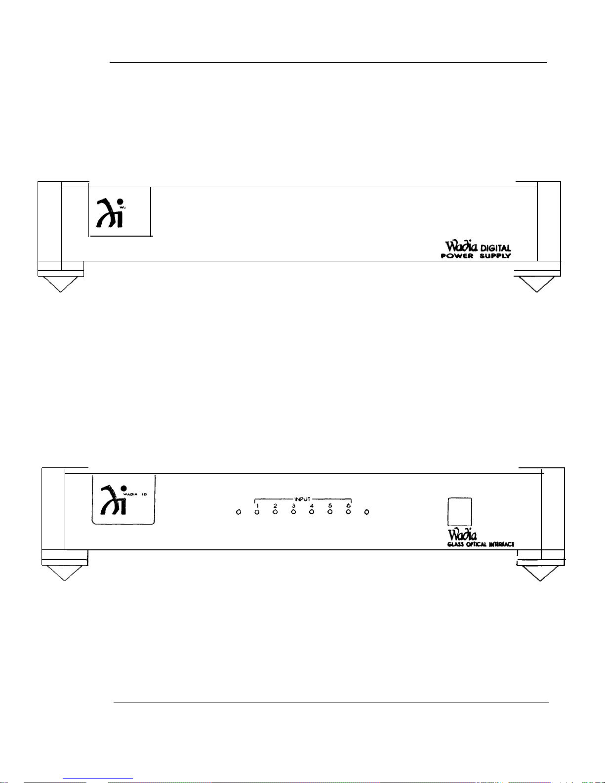
9 POWER SUPPLY:
The front panel of the Wadia 9 Power Supply has no lights nor displays any
information.
WADIA 10 GLASS OPTICAL INTERFACE:
The front panel of the Wadia 10 Glass Optical Interface has a series of eight
LEDs
across its face. When AC power is connected to it the first LED, POWER, is
illuminated. There are then a series of six
LEDs
which correspond to the six inputs.
The last LED is DATA, which will illuminate when an input is selected that has a
digital source connected to it.
POWER
I,,NwT45,
0
DATA
0
0
0
0
0
0 0 0
ti
DIGITAL
cuss WncAA wlEefM3
I
I
I
I
I
11
Page 14
Wadia 9 DECODING COMPUTER
REMOTE CONTROL
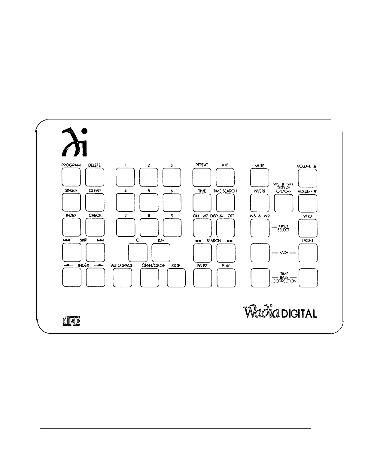
The remote control for the Wadia 9 Decoding Computer can also be used to
operate the functions of the Wadia 5
Transport and the Wadia 10 Glass Optical Interface. Only the functions that are
controlled on the Wadia 9 and Wadia 10 will be described in this Owner’s
Manual.
PowerDAC,
the Wadia 7 Compact Disc
lo+
LEFT l2GHT
n-FA+---
ml
-
ND!3
00
0
m
MUTE: Places the Wadia 9 Decoding Computer in
Decoding Computer is at absolute zero, or at no volume. Pressing the MUTE button again, or
either of the VOLUME buttons, will take the unit out of MUTE.
INVERT: Selects digital inversion of the music signal. The first time this button is pressed, it
calls the screen to the information window and displays it. Pressing this button again, while
the screen is visible in the information window, will change the status from, or to, INVERT.
-
AUTOSFXE
000
OPEN/CLOSE
SD’
PLAY
rlo
/
out of mute. Mute on the Wadia 9
CIiDIGITAL
REMOTE CONTROL
12
Page 15

Wadia 9
DECODING COMPUTER
VOLUME: These keys allow the digital volume control level to be decreased or increased on
the Wadia 9 Decoding Computer. There are 100 discreet levels to this volume control varying
in size from
l/5 dB
to 1 dB per step. If the Wadia 9 is to be connected to a pre-amplifier to
adjust volume, then the level should be set at its maximum (100).
WADIA 5
&
WADIA 9 DISPLAY ON/OFF: Some listeners prefer to listen in an environment
that is as dark as possible. There is some psycho-acoustic truth to the fact that when your
brain does not have to deal with the information presented to it by the sense of sight, it is
more capable of allowing the cues it is presented with through the sense of hearing to more
easily concentrate on the listening experience. By pressing this button the user can
extinguish the information window. The information in the window will re-illuminate whenever
a button is pressed that activates the display. Following about 5 seconds of illumination, the
display will once again go dark.
WADIA 5
&
WADIA 9 INPUT SELECT: Pressing this button will scroll through (1, 2, 3, 1,
etc.) the three inputs of the Wadia 9.
WADIA
10
INPUTSELECT:
Pressing
this
buttonwillscrollthrough
(1,2,3,4,5,6,1,etc.)
the six inputs of the Wadia 10.
LEFT and RIGHT FADE: Fade, for a digital volume control, is similar to Balance for an
analog volume control. Let us, for example, assume that you are listening at a level of 75 in
both channels (LEVEL LEFT 75, LEVEL RIGHT 75) and you would like to adjust the balance
between the left and right channels. By pressing the FADE LEFT button, the level of the left
channel will begin to diminish (LEVEL LEFT 74, LEVEL RIGHT 75; LEVEL LEFT 73, LEVEL
RIGHT 75; LEVEL LEFT 72, LEVEL RIGHT 75; etc.). Volume can then be adjusted with this
level offset (LEVEL LEFT 72, LEVEL RIGHT 75; LEVEL LEFT 73, LEVEL RIGHT 76; LEVEL
LEFT 74, LEVEL RIGHT 77; etc.). Finally, when you want to return the levels of both
channels to an equal setting, again using the above example, by pressing the FADE RIGHT
button the level of the left channel will rise until it is at the same level as the right channel
(LEVEL LEFT 75, LEVEL RIGHT 77; LEVEL LEFT 76, LEVEL RIGHT 77; LEVEL LEFT 77,
LEVEL RIGHT 77). Continuing to press the RIGHT FADE button would then cause the level
of the right channel to diminish (LEVEL LEFT 77, LEVEL RIGHT 76; LEVEL LEFT 77,
LEVEL RIGHT 75; LEVEL LEFT 77, LEVEL RIGHT 74; etc.).
TIME BASE CORRECTION: Pressing these two buttons once simultaneously calls the
INVERT, EMPHASIS, TIME BASE CORRECTED screen to the information window on the
front of the Wadia 9. Pressing them again toggles between the AUDIO MODE and the
VIDEO MODE.
During all purely listening sessions, the AUDIO MODE should always be in the signal path.
When watching a Laser Disc or other video format, which has a digital audio output that is
connected to the Wadia 9, the real amount of time that the audio signal is delayed as it goes
through the process of Time Base Correction in the AUDIO MODE may result in a
discrepancy between what is occurring visually on the screen and what is being heard
through the speakers. For this reason it is possible to change from the AUDIO MODE of
Time Base Correction circuit to the less time consuming VIDEO MODE of the Time Base
Correction circuit. Even when this is done, the input stage of the Wadia 9 operates in a
manner that is superior to the methods of re-clocking the digital signal that it receives by a
factor of
2500:1
over other commonly utilized methods.
Still, because we believe that all pure audio listening should be done with the AUDIO MODE
of the Time Base Correction circuit in the signal path, we have made it a two-button push to
get out of this mode, so that it is unlikely that you will remove it from the signal path
accidentally.
13
Page 16
Wadia 9
DECODING COMPUTER
REAR PANELS
WADIA
9 DECODING COMPUTER:
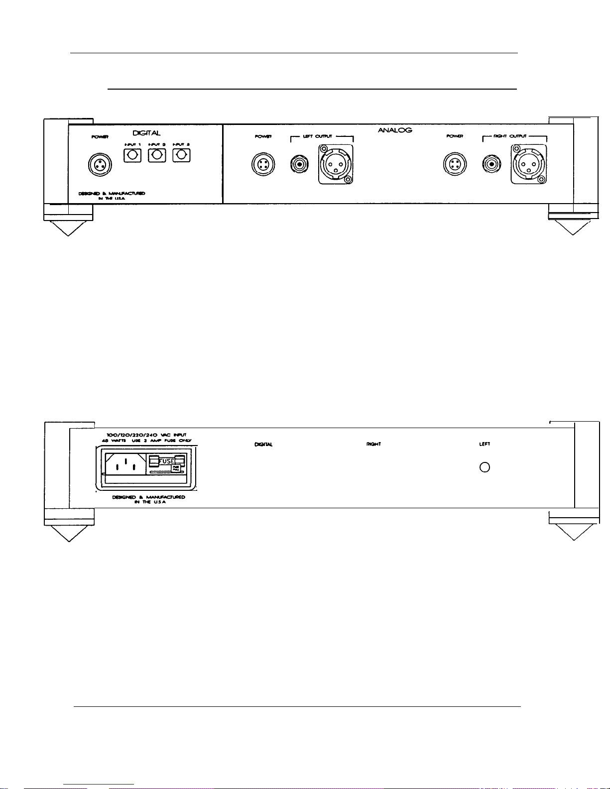
ANALOG OUTPUTS: For maximum convenience and functionality the Wadia 9 Decoding
Computer includes both single ended and balanced output connections. The single ended
connectors are the gold plated RCA type. The balanced connectors are professional quality
XLR type. (Pin
1 =
GROUND, Pin 2 = signal, Pin 3 = INVERTED SIGNAL).
DIGITAL INPUTS: For maximum performance the Wadia 9 Decoding Computer provides
three Glass Optical digital inputs. It is our assumption that a CD Transport with Glass Optical
Output will be connected to one of these inputs. Up to six non-Glass Optical Outputs can be
connected to a Wadia
10,
and the Glass Optical Output of the Wadia 10 can then be
connected to the second input of the Wadia 9. The third input of the Wadia 9 can be used for
accepting the output of an Analog to Digital Converter into which you have connected your
analog sources. In this way the Wadia 9 can operate as a complete control center (source
select and volume control) for an entire home entertainment system.
1
c
v
I,
WADIA 9 POWER SUPPLY:
I
0 0
LEFT
0
AC Power Connector: There is a standard 3-pin connector to which the AC cord should be
connected which will provide power to the Wadia 9 POWER SUPPLY. There are then three
cables which come out of the back of the Power Supply and should be connected to the
power supply connectors on the back of the Wadia 9 itself. These three power supply cables
are labeled LEFT, RIGHT, and DIGITAL on the rear of the Power Supply. The three
connectors are all labeled POWER on the rear of the Wadia 9 itself, under the appropriate
headings DIGITAL, LEFT ANALOG, and RIGHT ANALOG.
Like all digital audio products, best performance is achieved only after the product has been
on for 72 or more hours. Do not connect or disconnect the power cord unless the Wadia 9
Decoding Computer is not connected to another component in the system, or unless the
amplifier is either turned off or not connected to the loudspeakers.
14
Page 17
Wadia 9
DECODING COMPUTER
u
WADIA 10 GLASS OPTICAL INTERFACE:
The Wadia 9 has three Glass Optical Inputs. This is to ensure the highest quality digital
interconnection between it and digital sources. Certainly, if a digital source component has a
Glass Optical Output, it should be connected to the Wadia 9 directly through this connection
method. There are many digital source components, however, which do not have a Glass
Optical Output. Rather than risk the potential contamination of the circuitry of both the Wadia
9, and components further along in the rest of the system, by ground noise from digital
source components, Wadia requires that all digital source components that do not have
Glass Optical Outputs be connected to the Wadia 9 through the Wadia 10 Glass Optical
Interface.
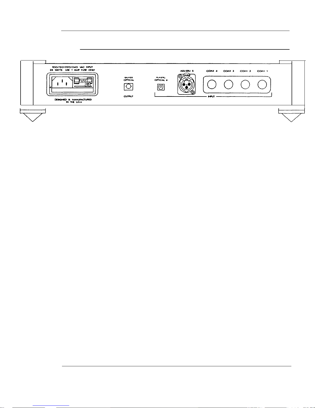
The Wadia 10 has six digital inputs (four coax via BNC connectors, and one each
AES/EBU
via XLR connector and
EIAJ
standard optical via a Toslink type connector) and a single
Glass Optical digital output. Through this device, digital source components that do not have
Glass Optical Outputs can be connected to the Wadia 9.
Coaxial digital interconnection is available through a high quality BNC type connector. If this
method of interconnection is chosen, it would be recommended that the cable of your choice
be terminated with a BNC type connector. A BNC to RCA adapter is provided with the
Wadia 10 Glass Optical Interface for those who would like to experiment with a number of
coaxial cables prior to having one terminated with a BNC connector.
The AES/EBU format is provided through an XLR type connector. When using this method of
digital transmission, be sure that the pin configuration on the associated equipment matches
that of the Wadia 9 (Pin 1: Ground, Pin 2: Not Inverted Signal, Pin 3: Inverted Signal).
AC Power Connector: There is a standard 3-pin connector to which the AC cord should be
connected which will provide power to the Wadia 10.
15
Page 18

Wadia 9
UNPACKING
Unpack your Wadia 9 Decoding Computer, Wadia 9 Power Supply, and Wadia 10 Glass
Optical Interface and keep all packing materials for future use. To avoid damaging the
connectors on the rear of the product, or those on digital output cables, never tip the product
back in a way that would put stress on these connectors. Carefully inspect the product for
damage and flaws. If any are found, immediately contact your Wadia dealer.
SET-UP AND INSTALLATION
Make sure that the Wadia 9 Decoding Computer is not plugged into the AC power supply
1)
and is disconnected from all associated equipment.
Place the Wadia 9 Decoding Computer on a flat, stable surface and turn it onto either of
2)
its sides (The finish of the metal work can be protected by first placing a soft cloth or
towel down onto which the Wadia 9 can be placed).
While the Wadia 9 is still on its side, screw in the four pointed feet into the bottoms of the
3)
four corner posts.
DECODING COMPUTER
Turn the Wadia 9 upright and place it in the desired location. Four bases are provided to
4)
be placed underneath the four pointed feet, for the protection of the furniture upon which
the product is to be placed.
Repeat steps 2, 3, and 4 for the Wadia 9 Power Supply and the Wadia
5)
Interface.
Connect one end of the power supply cord to the receptical on the rear of the Wadia 9
6)
Power Supply and the other to a wall outlet. Do the same for the Wadia 10 Glass Optical
Interface.
Connect the three umbilical cords (Left Analog Power, Right Analog Power, and Digital
7)
Power) from the back of the Wadia 9 Power Supply to the matching connectors on the
back of the Wadia 9 Decoding Computer.
Connect the single ended or balanced analog outputs of the Wadia 9 Decoding
6)
Computer to the input of a pre-amplifier or power amplifier. Please make certain that the
power to the preamplifier or amplifier is not on, or that the amplifier is not connected to
the loudspeakers before making this connection.
Connect a digital source to the Wadia 9.
9)
The Wadia 9 Decoding Computer powers-up at the lowest volume setting. Pressing the
9)
VOLUME
(no volume). Adjust the digital volume control to a safe level, i.e., a setting near the
bottom of the scale. This can be re-adjusted after the music starts to play.
h
button on the remote control will bring the unit out of the lowest volume level
10
Glass Optical
16
Page 19

Wadia 9
DECODING COMPUTER
10)
FOR USE WITH A PREAMPLIFIER: If the Wadia 9 Decoding Computer is to be used
with a preamplifier, and if the volume is to be controlled by the preamplifier and not the
Decoding Computer, then the Wadia 19 should be set for it’s maximum volume output.
To do this, you must press the VOLUME button on the remote control until the LEVEL
LEFT and LEVEL RIGHT are at their maximum setting of 100. This will bring the outputs
to the maximum level so that the preamplifier can control the system.
AC POWER CONNECTION
The proper voltage for this product is indicated on the AC Entry Module on the rear panel of
the chassis.
Double check proper voltage operation to ensure that the voltage at which this product is
manufactured to operate is consistent with the AC line voltage in your country.
This Wadia product has been manufactured to be used at one voltage only. If you plan to use
this product at a voltage which is different from the one indicated on the chassis, the product
must be returned to the Wadia factory for modification.
NOTE: The use of this product at a voltage other than that specified on the unit will almost
certainly cause irreparable damage to the Wadia 9, and is not covered by the Wadia
warranty.
Connect the
linecord
supplied with the system first to the Wadia 9 on the AC Entry Module
and then to the service outlet.
Unplug the unit immediately if it becomes wet.
In the event of fuse failure, locate the FUSE PULL tab on the AC Entry Module. Replace the
fuse only with the exact type and size fuse originally provided with the Wadia 9.
POWER-UP-RESET
The Wadia 9 Decoding Computer is totally reset upon power-up. If the system ever refuses
to operate, please turn off the amplifier and then disconnect the AC power cord from the
Wadia 9 Power Supply. After a minimum of 30 seconds, power-up the system and all
subsystems will be totally reset. The volume will be reset to zero.
Remember, the Wadia 9 Decoding Computer is a computer, and as with any computer, an
occasional reset may be necessary.
CARE AND MAINTENANCE
To clean the Wadia 9 Decoding Computer, use a soft cloth moistened with plain water. Don’t
apply water, dusting sprays, solvents, abrasives, or cleaning fluids directly to the chassis.
Make sure that the remote sensor window on the front of the product and the remote
control’s projection lens are kept clean and dust free. When the remote control’s batteries
need to be replaced, always replace both batteries at the same time. Always dispose of
batteries in a manner that is considerate of the environment.
17
Page 20

Wadia 9
DECODING COMPUTER
SERVICE
If you have a service problem, immediately contact your Wadia dealer. It is important that your Wadia
9 Decoding Computer be serviced only by an authorized Wadia service facility.This will ensure that
proper repairs are made and that your Wadia 9 warranty stays in effect throughout the warranty
period.
BATTERIES
The Wadia 9 and Wadia 10 are completely controlled by the Remote Control. If these products do not
respond to commands from the Remote Control, the useful life of the batteries may have expired.
Remove the back cover of the Remote Control (there are 4 screws in the 4 corners of the rear panel
on the Remote Control) and replace the two AA batteries.
WARRANTY
This warranty covers the Wadia 9 Decoding Computer. Wadia Digital warrants that this product shall
be free from defects in materials and workmanship for:
5 Years for all parts of the product (excluding batteries).
The warranty period begins at the time the product is first shipped from Wadia Digital and is subject
to the following requirements and understandings:
1)
The product must not have been modified in any manner whatsoever, or the warranty is
immediately voided.
2)
The product must not have been stored in a humid, damp environment; nor subjected to weather,
water or salt spray.
3)
During the warranty period Wadia Digital will repair the Wadia 9 to working order, or, at Wadia’s
option, replace a defective Wadia 9 with a similar available product, at no cost to the owner for
labor, materials, and shipping charges from Wadia Digital, River Falls, Wisconsin.
4)
Wadia Digital shall not, under any circumstances, be liable for any incidental or consequential
damages arising from the loss of property or other damage or losses due to the failure of a Wadia
9 Decoding Computer. Wadia Digital will not pay for loss of use or inconvenience caused by the
failure of a Wadia 9 Decoding Computer. Wadia Digital will not pay for damage caused to other
audio components caused by the failure of a Wadia 9 Decoding Computer within the limits
allowed by State Law.
5)
All repairs performed after the warranty period has expired will be billed to the owner and will
carry a 90 day warranty on parts and labor.
6)
All repairs must be performed by an authorized service facility or by Wadia Digital.
This
oroduct
is
onlv
warrantied in the
country of originalsale by Wadia Digital.
18
Page 21

Wadia 9
SPECIFICATIONS
DECODING COMPUTER
Resampling Rate
64
Times
Decoding Software
DigiMaster
Accomplished in software and hardware by doing 16 times Spline resampling
in DSP and 4 times of 1st order
LaGrangian
resampling in the
DACs.
22-bits
Resolution
Digital Volume
Control Range
Passband
Ripple
CPU Power
Signal Inverting
Math Resolution
Inverting Switch
Modularity/
Upgradeability
Dither
Output Level (0 dB ref)
Output
lmpedence
Channel Isolation
at 1
kHz
Channel-to-channel
phase error
PC Boards
Power Distribution
Power Supplies
Wadia 9 Power Supply
Wadia 10
Enclosures
Weight
Wadia 9 Decoding Computer
Wadia 9 Power Supply
Wadia 10
Dimensions
Wadia 9 Decoding Computer
Wadia 9 Power Supply
Wadia 10
50-dB
DC - 20
kHz
None (Monotonic)
128-MIPS
Digital domain
240 dB (40-bits)
Digital Domain
Programmable Gate Array Chip or hardware options and upgrades.
On round-offs
13 dBV
c 1 ohm (both single-ended and balanced)
>110 dB
<
0.5 degrees at 10
kHz.
(4) 1 l-layer signal carrying boards in the Main Unit.
Massive multiple power-plane layers.
3 Toroidal Transformers.
Toroidal Transformer.
The Wadia 9 Decoding Computer, the Wadia 9 Power Supply, and the
Wadia 10 Glass Optical Interface are of Airborne computer quality,
machined from a solid block of aluminum.
Detuned for Lenz’ s Law and package parasitic resonances.
Side panel skin effect transitions
@ <
20 Hz.
21 Ibs.
19 Ibs.
13 Ibs.
3.637” High, 17” Wide, and 14” Deep
3.637” High, 17” Wide, and 9” Deep
3.637” High, 17” Wide, and 9” Deep
Specifications subject to change without notice
19
Page 22

Page 23

Page 24

l
Al
%h%aDlGlTAL
 Loading...