

Page 1
WARNING: DISCONNECT POWER AT THE MAIN
FUSE BOX BEFORE INSTALLATION.
WARNING:
This xture is intended for installation in
accordance with the National Electrical Code
(NEC) and all local code specications. If you are
not familiar with code requirements, installation
by a certied electrician is recommended.
Before assembly, remove all parts and part
packages from box. If anything is missing, please
contact the retailer from which the product was
purchased.
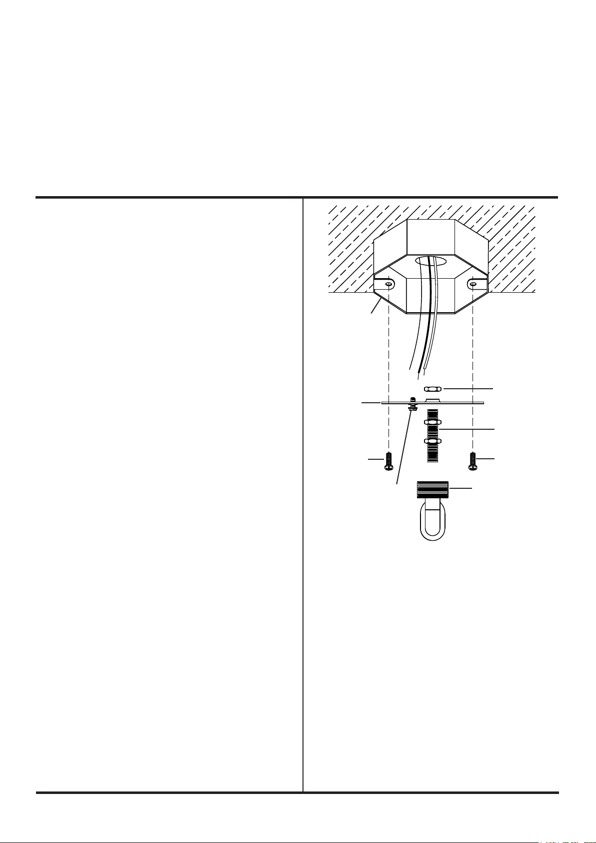
1. Carefully pull house wires down out of junction
box so house wires are easily accessed to
connect xture wires.
2. If screw collar loop (W) is already attached to
mounting bracket (A), proceed to Step 3. To
assemble screw collar loop (W) to mounting
bracket (A): Hold mounting bracket (A) so head
of ground screw is pointing down towards oor.
Hold threaded pipe so two hexnuts already
attached to threaded pipe (E) are pointing
down towards oor. From side of mounting
bracket with ground screw head, screw short
end of threaded pipe (E) into hole in center of
mounting bracket (A) until hexnut on threaded
pipe (E) touches mounting bracket. Thread
hexnut (V) onto end of threaded pipe (E).
Tighten hexnut (V) to secure threaded pipe (E)
to mounting bracket (A). Thread screw collar
loop (W) onto end of threaded pipe pointing
down towards oor. Tighten screw collar loop
up against hexnut on threaded pipe (E).
3. Place mounting bracket (A) up against junction
box. Screw collar loop (E) should be pointing
down towards oor. Align each slot in mounting
bracket (A) with each hole in junction box.
4. Thread one junction box screw (B) into each
slot in mounting bracket (A) and into holes
in junction box. Tighten junction box screws
(B) to secure mounting bracket (A) to junction
box. CAUTION: Make sure house wires are still
easily accessible. DO NOT pinch wires between
mounting bracket and ceiling.
ANY QUESTIONS CALL: 800-613-3261
JUNCTION
BOX
A
B
GROUND
SCREW
M-F 8:00AM-6:00PM ET
ITEM#: D3229
V
E
B
W
1
elkhome.com
Page 2
ITEM#: D3229
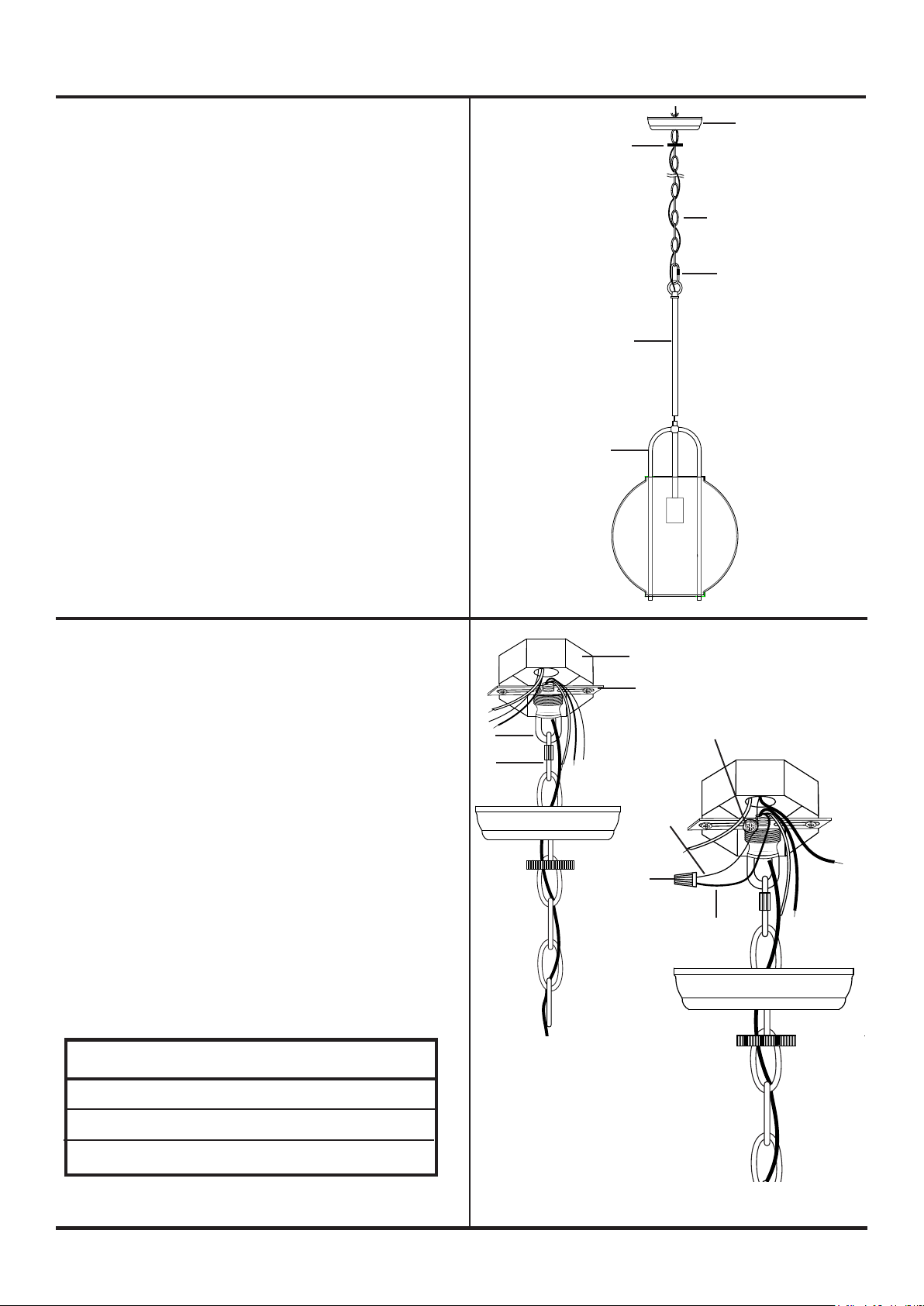
5. Carefully push xture wires up through hole in
bottom of center stem (M). Carefully pull wires out of
top of center stem (M). Screw center stem (M) onto
threaded pipe on top of xture body (O). DO NOT
pinch wires between center stem (M) and xture.
6. Attach locking link (G) to loop on top of center
stem (M).
7. Determine desired hanging height of xture.
Remove chain links to achieve desired height.
8. Slip one chain link at end of chain (H) over
locking link (G) on loop on top of center stem (M).
9. Weave xture wires through chain links,
skipping every other chain link.
10. Slip threaded ring (F) down over end of chain (H)
with xture wires.
11. Position canopy (D) so outside of canopy is
pointing down towards xture. Slip hole in
canopy (D) over end of chain (H).
D
F
H
G
M
O
12. Strip 3/4” of insulation from ends of xture
wires.
13. Carefully push xture wires up through hole
in screw collar loop (W) attached to mounting
bracket (A) and out end of threaded pipe inside
junction box. Carefully pull xture wires so they
are easily accessible to connect to house wires.
14. To aid in connecting xture wires to house
wires, temporarily connect second locking link
(G) to link at end of chain (H) and to screw collar
loop (W).
15. Slightly loosen ground screw on mounting
bracket (A). Do not completely remove ground
screw. Wrap house ground wire (copper)
around ground screw, leaving enough ground
wire to attach to xture ground wire. Twist
end of xture ground wire and end of house
ground wire together. Twist wire connector (C)
onto ends of wires. Completely tighten wire
connector (C). Reference chart below for correct
wire connections.
Connect Supply (House) Ground Copper Wire to:
Bare Copper Wire or,
W
G
JUNCTION BOX
A
GROUND
SCREW
HOUSE
GROUND
WIRE
(COPPER)
C
FIXTURE
GROUND
WIRE
Bare Silver Wire or,
Green Insulated Wire.
2
elkhome.com
Page 3
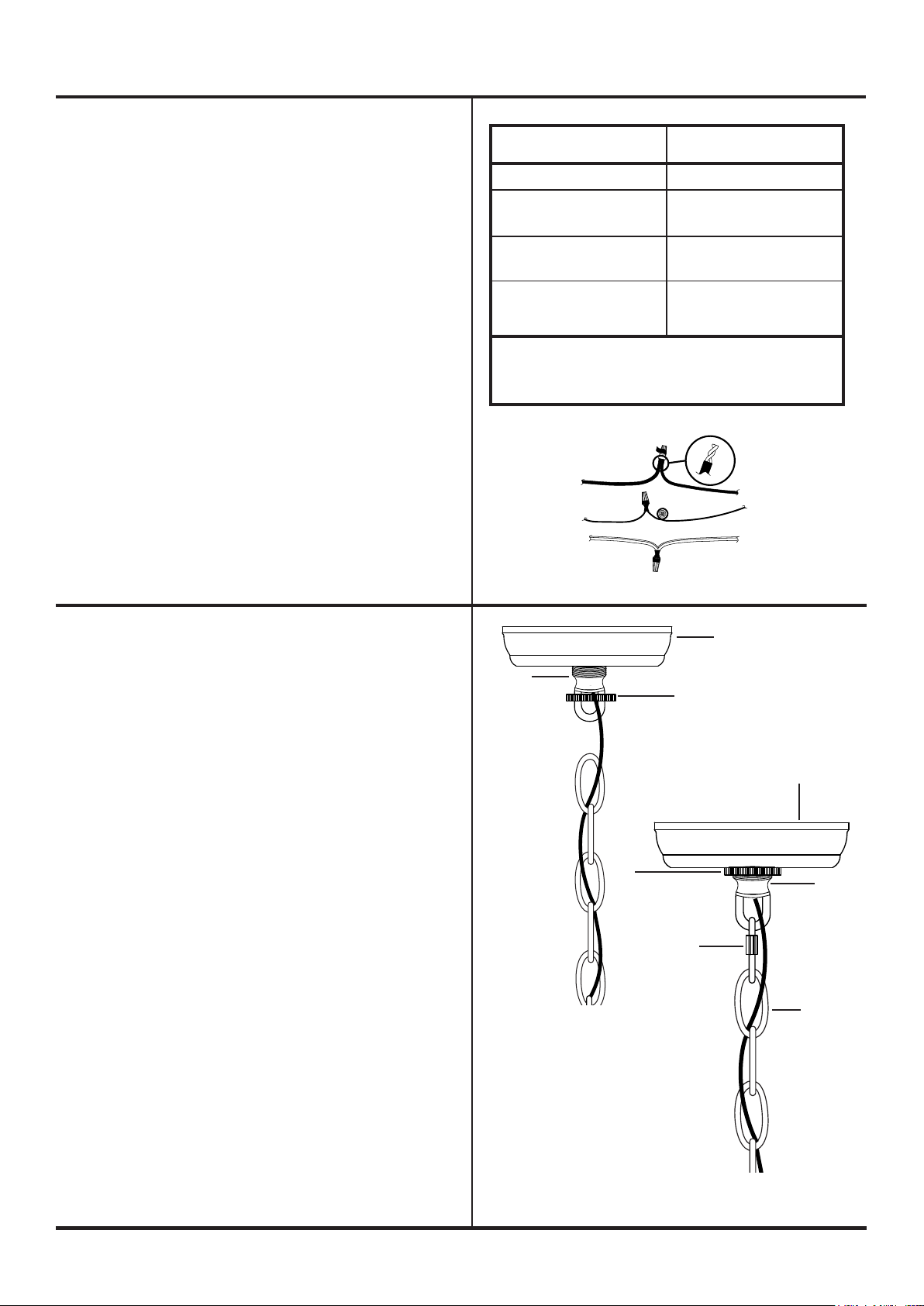
16. Twist end of house lead wire (black) and end of
xture lead wire together. Twist wire connector
(C) onto ends of wires. Completely tighten wire
connector (C). Twist end of house neutral wire
(white) and end of xture neutral wire together.
Twist wire connector (C) onto ends of wires.
Completely tighten wire connector (C). Reference
chart to the right for correct wire connections.
17. Wrap electrical tape (not included) around wire
connectors (C) and wires. Ensure wires are
securely fastened into wire connectors.
18. Carefully push all wires and wire connectors into
junction box.
ITEM#: D3229
Connect Black Lead
Supply (House) Wire to:
Black Wire or,
*Parallel Cord
(Round and Smooth) or,
No printed words on
wire insulation or,
Insulated Wire
(other than green)
with Copper Conductor.
*When parallel wire (SPT 1 & SPT 2) is used:
The lead wire is round in shape or smooth.
The neutral wire is square in shape or ridged.
Connect White Neutral
Supply (House) Wire to:
White Wire or,
*Parallel Cord
(Square and Ridged) or,
Printed words on
wire insulation or,
Insulated Wire
(other than green)
with Silver Conductor.
19. Remove second locking link (G) from last link on
chain (H) and screw collar loop (W).
20. Raise canopy (D) up to ceiling. Pass hole in
canopy (D) over screw collar loop (W). Position
canopy (D) up against ceiling.
21. Raise threaded ring (F) up to canopy (D). Screw
threaded ring (F) onto screw collar loop (W).
Tighten threaded ring (F) to secure xture to
ceiling.
22. Attach second locking link (G) to link at end of
chain (H). Attach locking link (G) at end of chain
(H) to loop on screw collar loop (W).
FIXTURE LEAD WIRE HOUSE LEAD WIRE
FIXTURE GROUND
WIRE
FIXTURE NEUTRAL
WIRE
(BLACK)
HOUSE GROUND
WIRE (COPPER)
HOUSE NEUTRAL WIRE
(WHITE)
D
W
F
D
F
W
G
H
3
elkhome.com
Page 4
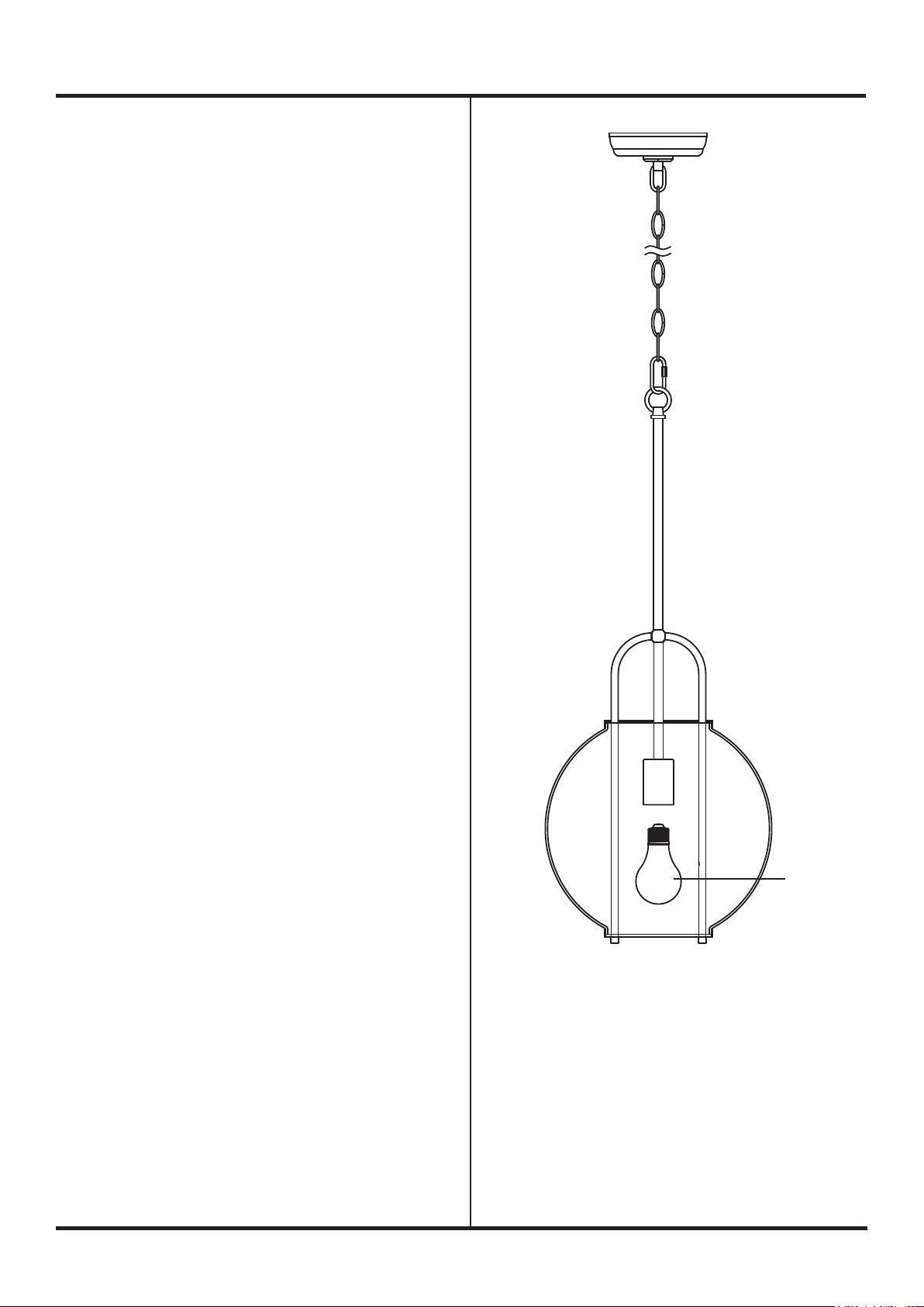
23. Screw recommended bulbs (E26 Edison bulb
type, not included) into socket. Verify correct
bulb wattage marked on socket of xture.
WARNING: DO NOT exceed maximum bulb
wattage.
ITEM#: D3229
BULB
4
elkhome.com
 Loading...