

Page 1
INSTALLATION INSTRUCTIONS
WARNING
DISCONNECT POWER BEFORE RELAMPING OR WIRING THE FIXTURE.
READ ALL INSTRUCTIONS COMPLETELY BEFORE STARTING INSTALLATION.
CAUTION
TO AVOID THE RISK OF FIRE OR SHOCK, FIXTURE MUST BE INSTALLED IN COMPLIANCE WITH
•
ALL APPLICABLE NATIONAL AND LOCAL ELECTRICAL/BUILDING CODES.
INSTALLATION AND MAINTENANCE OF THIS UNIT REQUIRES AN ELECTRICIAN OR
•
CERTIFIED FACTORY TRAINED TECHNICIAN.
• If an existing fixture is being replaced, remove it and note to which of the wires in the outlet box the fixture was attached.
DO NOT SEPARATE ANY OTHER WIRES THAT MAY BE IN THE BOX. DO NOT DAMAGE THE INSULATION OF OLDER WIRING.
In regular circumstances the BLACK wire will be the "Hot" lead and the WHITE wire will be the "Neutral" or "Common" lead.
A GREEN or BARE COPPER wire is the "Ground". In older buildings it is always good practice to reconfirm the polarity of the wiring.
NOTICE
• The important safeguards and instructions outlined on this sheet cannot cover all possible conditions and situations that may occur.
It must be understood that common sense, caution and care are factors that cannot be built into any product.
Caution and care must be supplied by the person(s) installing, operating and caring for this lighting fixture.
• This fixture is designed to be mounted on a correctly installed standard round or octagon box or a through wiring box
with a plaster frame. The box must be securely mounted to the structure of the building.
The crossbar and hardware supplied should be used. Directly mounting the fixture to the outlet box may make it impossible to
correctly align the fixture.
FIXTURE PREPARATION
1. Remove the fixture, parts and parts bag(s) from the carton.
NOTICE:
Before discarding the carton, double check to make certain that all parts are found
FIXTURE INSTALLATION
1. Thread the 2 mounting screws into the mounting bar. (The green screw is in the front). Attach the mounting bar to the outlet box.
Then thread the nipple into the crossbar and the hex nut onto the nipple.
2.Removethe threaded ring from the screwcollar loop. Fully thread the screwcollarloopontothe nipple. Place the canopy over the
screwcollarloopand againstthe ceiling.
Then remove the canopy and
3. Open end links of chain and attach the chain to the screwcollar loop.Closethe top link of chain.
desired height. Remove excess chain.
4. Unscrewtheringfromthe screwcollarloop. Let the ring and canopy slide down the chain to the top of the fixtur
Thread the lead wires and ground wire (first) through chain, ring and then the canopy.
tighten the hex nut against the crossbar.
Adjust the nipple so that 1/4" of threads on the screwcollar loop extend beyond the canopy.
Close the bottom link of chain on fixture loop ring.
.
Hang the fixture on the chain at the
5. When the ceiling is reached, measure 6" beyond the chain and cut off the excess wire. Separate the leads and strip of approx. 1/2"
of insulation from each lead.Twist the strands of wire together. Push the leads and ground wire upthrough the screwcollarloopand
nippleand into the outlet box.
6. Fasten the ground wire to the green or bare copper wire
in the outlet box or to the green screw on the crossbar.
WARNING
Never fasten the ground wire to the black or "hot" wire!
Failure to follow this instruction could result in
serious injury or death!
Page 2
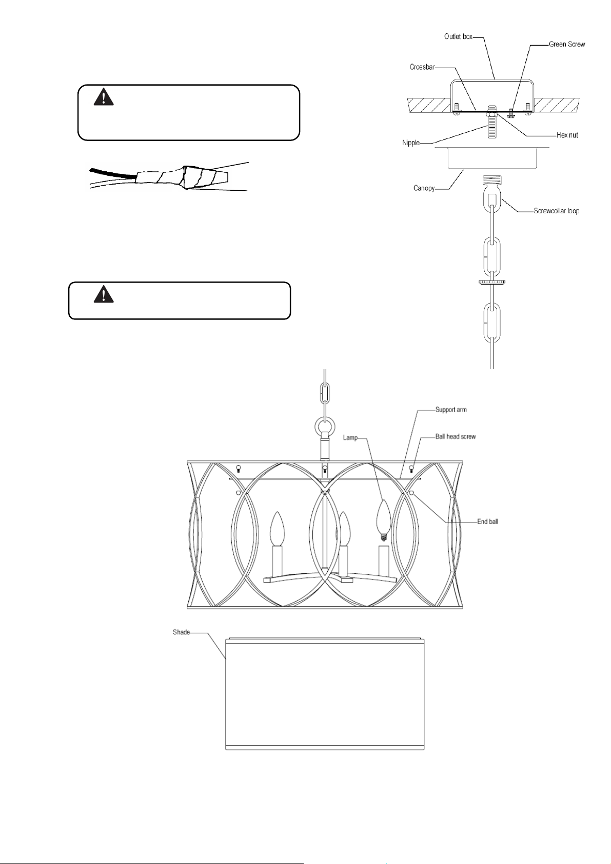
7. Fasten the white fixture lead to the white wire in the outlet box.
(
)
Fasten the wires together with an approved fastener (wire nut). Starting about 1' below the fastener, tightly wrap
the connection with electrical tape so that the connection seals the end of the fastener.
WARNING
Make sure that there is no exposed wire or strands that
could cause a dangerous short circuit !
electrical tape
approved fastener
wire nut
8. Connect the black fixture lead to the black wire in the outlet box. Fasten the joined wires as in step 7.
9. Slide the canopy and screwcollar ring up the chain and secure the canopy to the ceiling.
10. Install the lamps ( light bulbs). NOTE: This fixture is rated for Max 60 watt type B, BA, C, CA lamps.
WARNING
DO NOT EXCEED RECOMMENDED WATTAGE!
Using theball head screws and end balls, fasten the shade to the supportarms
11.
12. Restore power to circuit at breaker or fuse box.
2
 Loading...