

Please Note: A qualified structural engineer
Instruction Sheet
should be consulted prior to mounting an
antenna on a tower or support structure.
30406-001 Rev. J
J-SERIES MATV ANTENNA (VHF AND FM)
Description
The J-series Yagi antennas are heavy duty 75-ohm or 50-ohm antennas, for MATV and CATV applications.
Assembly and Mounting
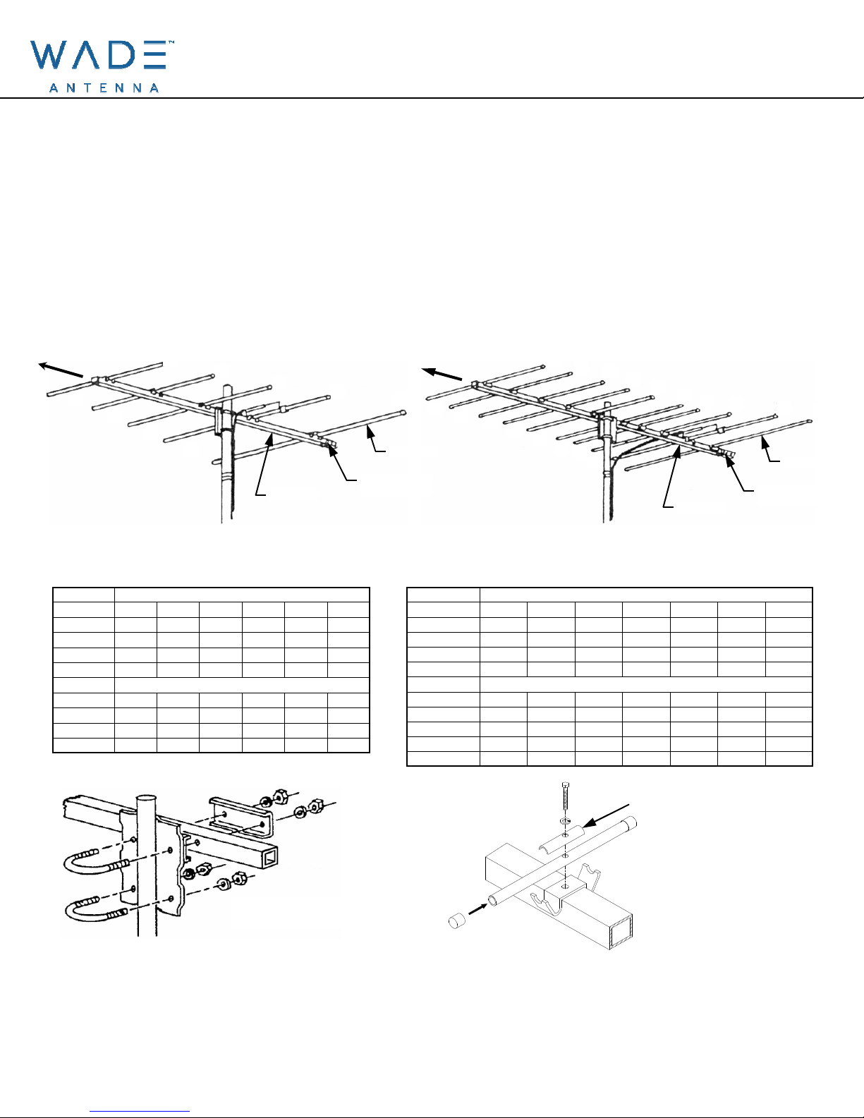
1. Consult Figure 1 or 2 and Table 1 or 2, then assemble the elements onto the crossarm in their proper
positions as denoted by their length. Note that the back of the crossarm is the end with the orange
plastic plugs. DO NOT overtighten the hex-bolts securing the elements.
5
D
C
B
4
A
3
CROSSARM
2
FIGURE 1 TYPICAL MOUNTING OF MODEL J55-*-WC
1
ELEMENT
ORANGE PLASTIC
PLUG
E
E
E
FIGURE 2 TYPICAL MOUNTING OF MODEL J105-*-WC
10
9
8
7
6
5
E
E
D
C
B
A
CROSSARM
NOTE: THESE ANTENNAS CAN BE CONVERTED TO A CANTILEVER MOUNT BY APPLYING A “WC” CANTILEVER MOUNTING KIT
TABLE 1 ANTENNA ELEMENT LENGTH (in inches)
ELEMENT J55-2 J55-3 J55-4 J55-5 J55-6 J55-FM
1
2
3
4 & 5
SPACE
A
B
C
D
110 100.5 89 77 70 65
100.5 91 81.5 70.5 65.5 58.5
92 85 76.5 66.5 62 50
85 81 73 63 60 48.5
ANTENNA ELEMENT SPACING (in inches)
25.5 24.5 28 24 21.25 21.5
15.75 15.25 16 12 12 6.75
11.5 9 8.5 8 7 12.25
39.5 30 25.5 26 20.75 28.5
TABLE 2 ANTENNA ELEMENT LENGTH (in inches)
ELEMENT J105-7 J105-8 J105-9 J105-10 J105-11 J105-12 J105-13
1
2
3
4 - 10
SPACE
A
B
C
D
E
33.5 32.5 31.25 30.5 30 28.5 27
30.5 29.5 29.5 28 27.25 26.375 25.375
27.625 27 26 25.5 25.375 23.25 23
26 24.5 24.25 23.875 22.75 22.25 21.5
ANTENNA ELEMENT SPACING (in inches)
8.75 11 11 9.25 8.875 9.5 11
10.5 9.25 9.25 6.875 9.75 9.75 9.375
7.5 7 7 7.5 7.125 5.625 6.5
8.5 10.5 10.5 10 9.625 9.75 8
11 10.5 10.5 10 9.625 8.5 8
4
3
2
1
ELEMENT
ORANGE PLASTIC
PLUG
FIGURE 3 TYPICAL MOUNTING
OF MODEL J55 AND J105
2. Loosely assemble the dual "U" bolt mounting bracket onto the crossarm as shown in Figure 3.
3. Lift the antenna into position, hold it upright and slide its "U" bolt assembly onto the mast.
4. Orient the antenna in the desired direction, then tighten the hex nuts on the "U" bolts sufficiently for
supporting the antenna.
ELEMENT STIFFENER
FIGURE 3A DIRECTOR ASSEMBLY
DETAIL (J105 SERIES ONLY)
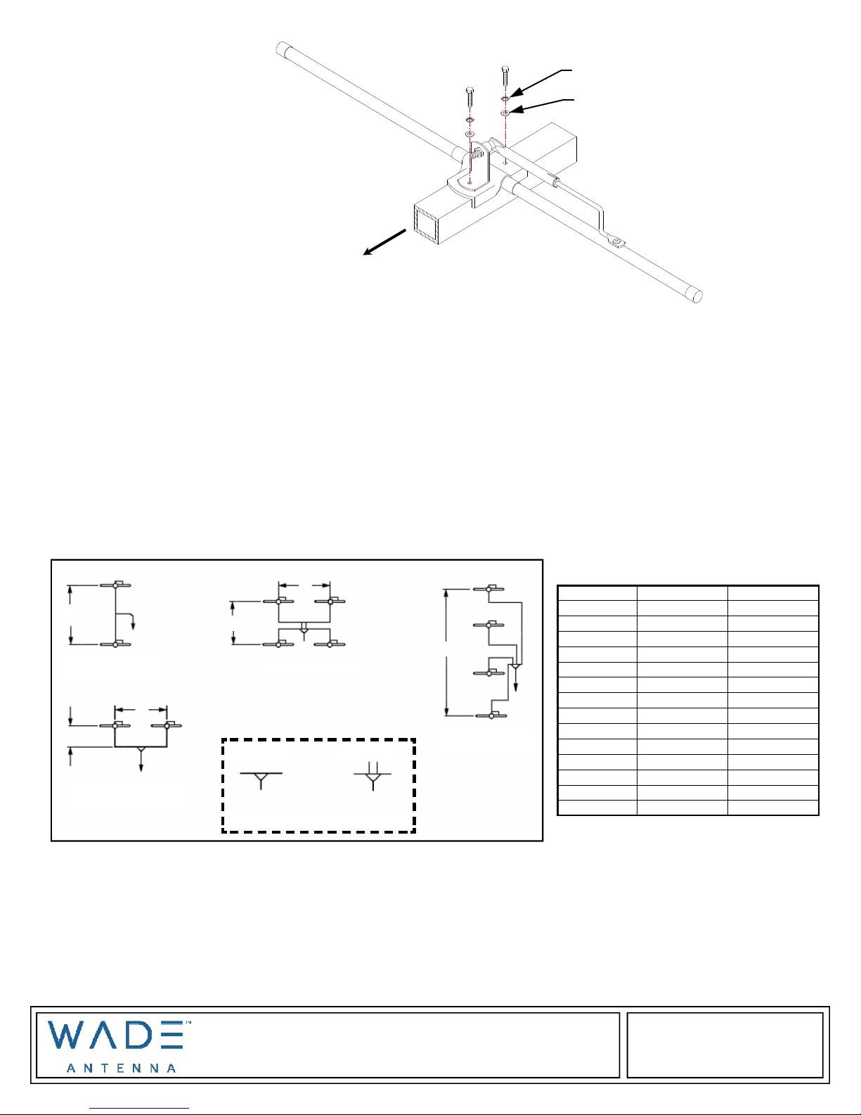
FIGURE 4 DIRECTOR & DIPOLE
ASSEMBLY DETAIL (J55 & J105 SERIES )
LOCK WASHER (Internal Tooth)
FLAT WASHER
T
N
O
R
F
Down Lead Connection
Attach down lead and weatherproof connection appropriately.
Final Orientation
Rotate the antenna until maximum signal strength is received, then fully tighten the hex nuts on the "U" bolt
assembly.
Arrays
J-Series 75-ohm antennas may be attached both vertically and horizontally for greater gain and directivity. It
is essential that the spacings given below in Figure 4 and Table 3 be strictly adhered to for best possible
results.
The gamma feeds of all antennas within the array must face in the same direction for proper polarity. Note
that the feeds shown in Figure 4 all face right as viewed from the front of the antenna.
A
2 - BAY
VERTICAL ARRAY
B
A/2
2 - BAY
HORIZONTAL ARRAY
B
A
QUAD ARRAY
TWO WAY FOUR WAY
SYMBOL INDICATES SPLITTERS
3A
4 - BAY
VERTICAL ARRAY
MODEL DIMENSION A DIMENSION B
J55-2
J55-3
J55-4
J55-5
J55-6
J55-FM
J105-7
J105-8
J105-9
J105-10
J105-11
J105-12
J105-13
(in inches) (in inches)
140 208
127 188
116 172
102 150
94 140
80 120
54 74
52 72
50 70
48 67
46 65
45 63
44 61
Splitting harnesses may be made from any good quality 75-ohm coaxial cable such as RG-6/U and Jerrold
Model F-659 (pat.pend.) adjustable coaxial connectors, Jerrold Model 1596A two-way or Model 1597 fourway splitters are recommended. These should be used with Model HB-1 outdoor housings for weather
protection. Instructions for use are supplied with each splitter. Consult your Jerrold dealer. Each leg of the
harness should be as short as and directly routed as practical with no sharp bends, length is not critical.
However, the pairs of input cables for each 1596A splitter or pair of splitters must be of equal length; the
four input cables for Model 1597 splitters must also be of equal length.
Brantford, Ont., Can., N3T 5L8
29 Sharp Rd,
www.wadeantenna.com
 Loading...