

ALWAYS INSTALL WITH
FITTING UP & OPEN
SIDE OF LOOP DOWN
POSITION FOR OPTIMIZATION
FOR CHANNELS 14-27
Instruction Sheet
30219-001 Rev. L
08/04/08
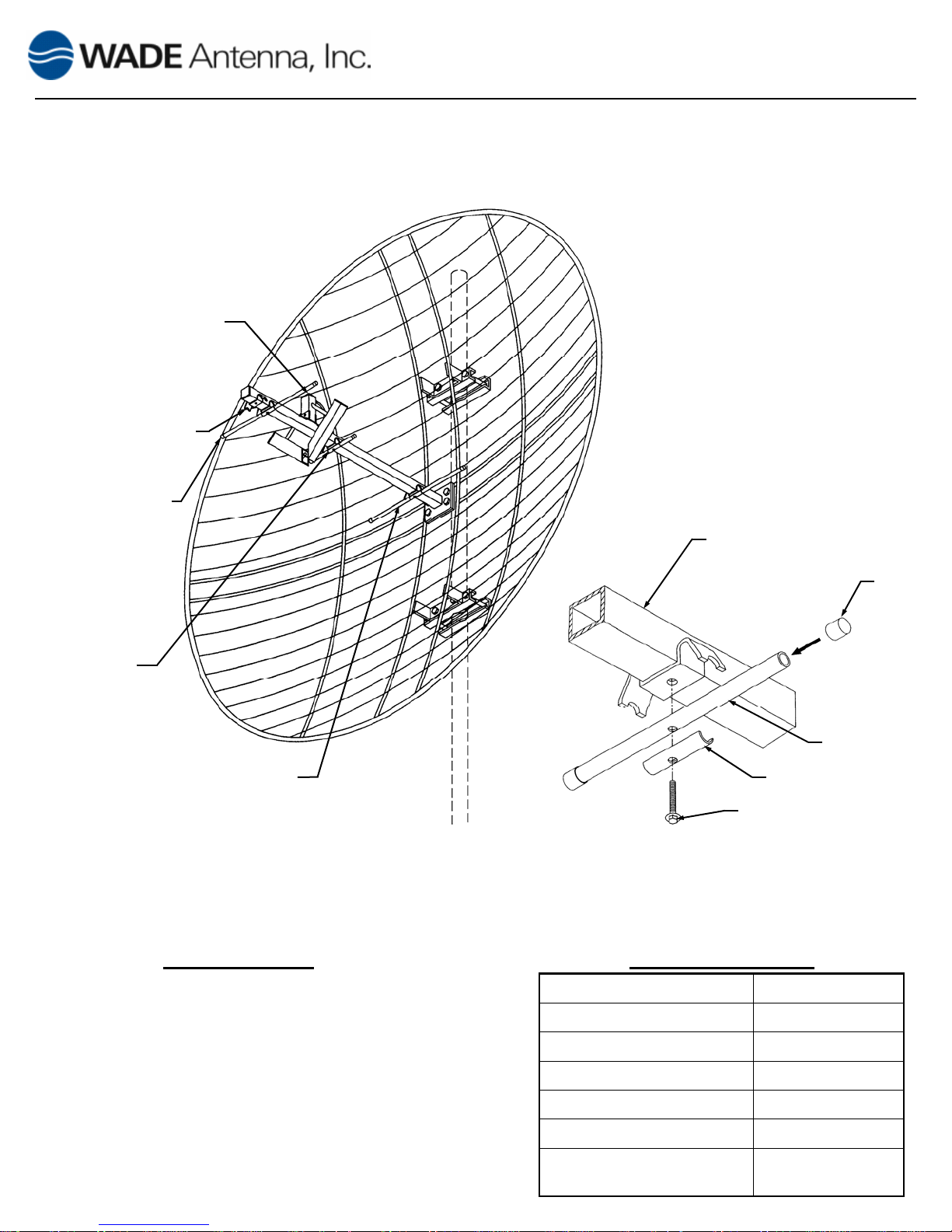
PARABOLIC SCREEN UHF ANTENNA
MODEL D-1338BB
14” FRONT REFLECTOR
ELEMENT
5” ELEMENT
14” ELEMENT
Figure 1
TYPICAL INSTALLATION
DRIVER CROSSARM
CAP
ELEMENT
ELEMENT STIFFENER
10-32 X 1¼” HEX BOLT
WITH LOCKWASHER
Figure 2
ELEMENT ASSEMBLY DETAIL
DESCRIPTION
TACO Model D-1338BB is designed for
UHF reception and low-power transmission.
Each unit consists of a four foot diameter,
grid type parabolic reflector of narrowly
spaced rods, a diamond loop driver with 75
ohm type “F” connector and all necessary
hardware for installation on a 1½ to 4½ inch
diameter mast or tower leg.
SPECIFICATIONS
Channels
Gain (dbi)
Power Input (Max)
VSWR (Max)
Front to back ratio (db)
Shipping Weight (lbs)
Thrust (lbs) 100 MPH
14-83
14-17.5
225 Watts
1.6:1
20
25
No ice: 74
½” Radial ice: 623
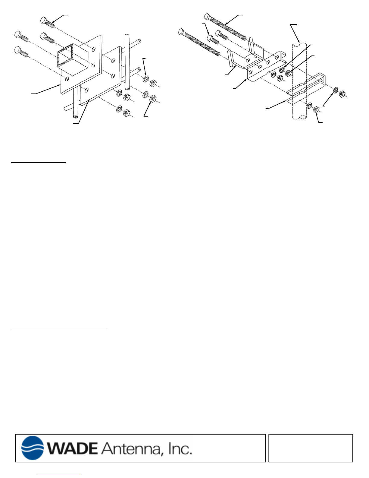
¼-20 X 1” HEX BOLT
¼-20 X 1” HEX BOLT
3/8-16 X 8” HEX
MAST OR TOWER LEG
1½ to 4½ in. O.D. Max
LOCKWASHER
¼-20 HEX NUT
LOCKWASHER
3/8-16 HEX NUT
DRIVER
SCREEN CENTER PLATE
DRIVER ASSEMBLY
Figure 3
LOCKWASHER
REFLECTOR-BRACKET
INNER CLAMP-BRACKET
OUTER CLAMP-BRACKET
¼-20 HEX NUT
Figure 4
CLAMP ASSEMBLY
INSTALLATION:
1. Assemble the driver to the center plate of the screen using four (4) of the packaged ¼-20 x 1” hex head bolts,
lockwashers and hex nuts. See Figure 3.
2. If optimization of reception is desired on channels 14-27, remove the front reflector element of the driver and
locate it in the forward position. See Figures 1 and 2.
3. Secure the inner clamp-brackets to the reflector-brackets using the remaining ¼-20 x 1” hex head bolts,
lockwashers and hex nuts. See Figure 4.
NOTE: It may be expedient to connect the down-lead at this time by following the procedure given
below under DOWN-LEAD CONNECTION.
4. Hoist the antenna into position on the mast, or tower leg, with the coaxial fitting side of the driver facing up
as shown in Figure 1. Take care not to damage the driver while hoisting the antenna.
5. Orient the antenna in the desired direction, then assemble the outer clamp-brackets with the 3/8-16 x 8” hex
head bolts, lockwashers and hex nuts, securing the antenna to the mast or tower leg; tighten the clamp-
brackets sufficiently to bear the antenna’s weight. See Figure 4.
DOWN-LEAD CONNECTION:
1. Prepare the end of the cable.
2. Feed the cable through the rear of the dish, then thread the connector onto the output fitting.
3. Hand-tighten then wrench-tighten the fitting no more than 1/6 of a turn. Apply a liberal coating of weather proofing compound to the connection and slide the weatherboot into place.
4. Route the down-lead to the point of entry by the shortest practical route securing it with cable ties. DO NOT
crush or distort the cable.
29 Sharp Rd, Box 1206
Brantford, Ont., Can., N3T 5L8
www.wadeantenna.com
 Loading...