

Page 1
INSTALLATION INSTRUCTION
Silo Multiples - New Construction Housing
MT-4*15, MT-4*10
IMPORTANT SAFETY INSTRUCTIONS
1. Read all instructions before installing.
2. System is intended for installation by a qualified electrician in accordance with the National Electrical Code and
local regulations.
3. Go to the main fuse box, or circuit breaker. Place the main power switch in the “OFF” position and unscrew the fuse(s) or switch ”OFF”
the circuit breaker switch(es) that control the power to the fixture or room that you are working on.
4. Place the wall switch in the “OFF” position.
INSTRUCTIONS DE SÉCURITÉ IMPORTANTES
1. Lisez toutes les instructions avant d’installer.
2. Système est destiné à être installé par un électricien qualié en conformité avec le code national de l’électricité et
les règlements locaux.
3. Accédez au panneau central de disjoncteurs ou de fusibles de votre demeure et placez l’interrupteur principal en position d’arrêt («OFF »).
4. Placez l’interrupteur mural en position d’arrêt (« OFF »).
OVERVIEW:
Housing is new construction Airtight IC and Non IC. (Refer to table below).
SPECIFICATION:
INPUT INSTALLATION DIMMING
120-277 VAC ; 50/60 Hz IC for -10 model (10W) TRIAC / ELV (120V only) / 0-10V
NON IC for -15 model (15W)
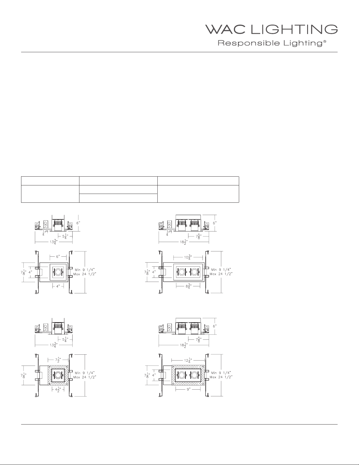
SINGLE LIGHT - TRIMMED
SINGLE LIGHT - TRIMLESS
waclighting.com
Phone (800) 526.2588
Fax (800) 526.2585
WAC Lighting retains the right to modify the design of our products at any time as part of the company's continuous improvement program. JULY, 2018
DOUBLE LIGHT - TRIMMED
DOUBLE LIGHT - TRIMLESS
Headquarters/Eastern Distribution Center
44 Harbor Park Drive
Port Washington, NY 11050
Central Distribution Center
1600 Distribution Ct
Lithia Springs, GA 30122
FOR THREE AND FOUR LIGHT MODELS:
CONTINUE TO NEXT PAGE
Western Distribution Center
1750 Archibald Avenue
Ontario, CA 91760
1
Page 2
INSTALLATION INSTRUCTION
Silo Multiples - New Construction Housing
MT-4*15, MT-4*10
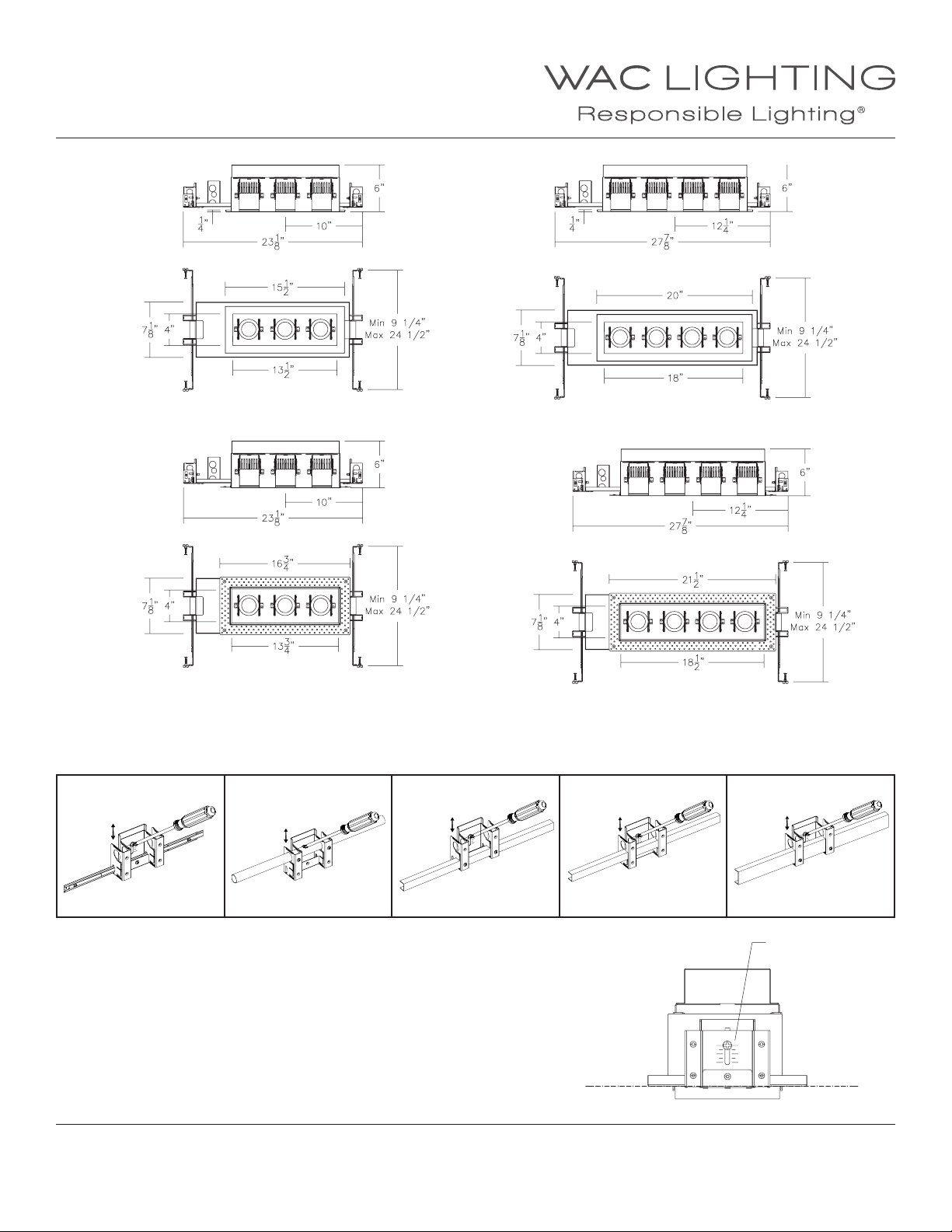
FIG. 1
HANGER BAR
TRIPLE LIGHT - TRIMMED
TRIPLE LIGHT - TRIMLESS
ROUND CHANNEL
FIG. 2
QUADRUPLE LIGHT - TRIMMED
QUADRUPLE LIGHT - TRIMLESS
1/2” CHANNEL
FIG. 3 FIG. 4 FIG. 5
3/4” CHANNEL
1 1/2” CHANNEL
TRIM HOUSING INSTALLATION
1. Housing features mounting brackets that can be used with hanger bars or
various channel suppor ts (See FIG. 1-5). Adjust the brackets to proper height by
loosening the screws such that the bottom of housing is ush to top of nished
ceiling plane (See FIG. 6). Retighten screws securely.
2. Slide the male and female hanger bars or other channel supports through the
appropriate holes in the brackets.
waclighting.com
Phone (800) 526.2588
Fax (800) 526.2585
WAC Lighting retains the right to modify the design of our products at any time as part of the company's continuous improvement program. JULY, 2018
Headquarters/Eastern Distribution Center
44 Harbor Park Drive
Port Washington, NY 11050
Central Distribution Center
1600 Distribution Ct
Lithia Springs, GA 30122
FIG. 6
Loosen screws to
adjust brackets
Western Distribution Center
1750 Archibald Avenue
Ontario, CA 91760
2
Page 3
INSTALLATION INSTRUCTION
Silo Multiples - New Construction Housing
MT-4*15, MT-4*10
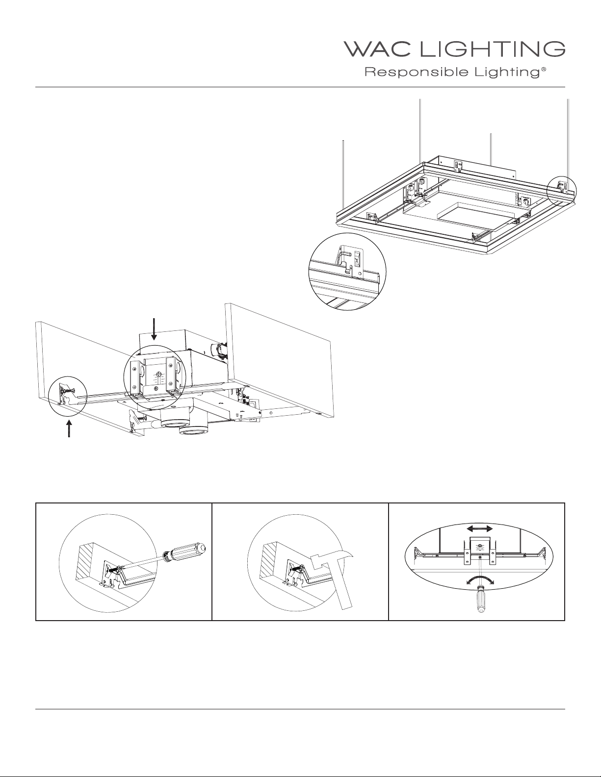
3. A. For hanger bar installation on grid:
Hanger bars are notched on the ends to t over “T” bars in the suspended
ceilings supported with tie wires (by others) to upper ceiling structure
(See FIG. 7).
B. For hanger bar installation on joists:
Install the hanger bar and housing assembly such that the lip of the hanger
bar rests on the bottom surface of the joist. Use a screw-driver or hammer to
secure the “screw-nail” into the wood (See FIG.8).
FIG. 8
FIG. 7
4. Slide the housing along the hanger bars to the desired position (See Detail. C).
Tighten bottom locking screws to secure the housing in place
Detail A Detail B Detail C
waclighting.com
Phone (800) 526.2588
Fax (800) 526.2585
Headquarters/Eastern Distribution Center
44 Harbor Park Drive
Port Washington, NY 11050
Central Distribution Center
1600 Distribution Ct
Lithia Springs, GA 30122
Western Distribution Center
1750 Archibald Avenue
Ontario, CA 91760
WAC Lighting retains the right to modify the design of our products at any time as part of the company's continuous improvement program. JULY, 2018
3
Page 4
INSTALLATION INSTRUCTION
Silo Multiples - New Construction Housing
MT-4*15, MT-4*10
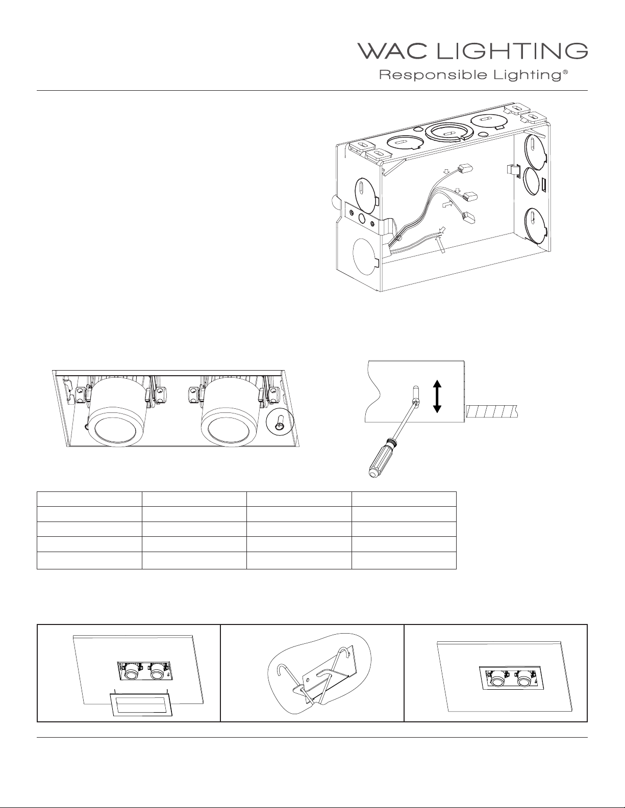
5. Remove xture junction box door and connect xture wires to
building wires: insert each supply wire into appropriate junction
box connector. This xture features electronic low voltage ELV,
TRIAC, or 0-10V dimming capabilities (See FIG 9).
To utilize ELV or TRIAC, wire black (line hot), white (line neutral)
and green (ground) in accordance to dimmer specications.
To utilize 0-10V dimming, wire purple (dim+), gray (dim-), black
(line hot), white (line neutral) and green (ground) in accordance
to dimmer specications.
When not using a dimmer, connect black xture wire to hot, white
xture wire to neutral and green xture wire to ground. Leave all
other wires capped individually.
Place all wiring and connectors back in junction box and replace
the junction box cover.
6. When installing in drywall, cut a hole in the drywall (see the following
cutout table). After nished, if necessary, adjust the xture for ceiling
thickness by loosening the housing screws. (See FIG 10 and FIG 11).
FIG. 10
FIG. 9
FIG. 11
Black
White
Green
Grey
Purple
Black:
Green:
White:
Purple:
Grey:
Line Hot
Ground
Line Neutral
0-10V Dim+
0-10V Dim-
Use template supplied to make appropriate cutout.
TRIMMED CUTOUT TRIMLESS CUTOUT
MT-4115T*/4110T* 5 1/8”X5 1/8” MT-4115L*4110L* 5 1/8” X 5 1/8”
MT-4215T*/4210T* 9 3/4”X5 1/8” MT-4215L*/4210L* 9 3/4” X 5 1/8”
MT-4315T*/4310T* 14 1/2”X5 1/8” MT-4315L*4310L* 14 1/2” X 5 1/8”
MT-4415T*/4410T* 19 1/8” X 5 1/8” MT-4415L*/4410L* 19 1/8” X 5 1/8”
TRIM INSTALLATION
1. Raise the trim to the housing and attach two sides by securing the torsion spring in the anchor cleat (as Fig.12, Fig.13).
2. Push the trim ush up against the ceiling (as Fig.14).
Fig. 12 Fig. 13
waclighting.com
Phone (800) 526.2588
Fax (800) 526.2585
Headquarters/Eastern Distribution Center
44 Harbor Park Drive
Port Washington, NY 11050
Central Distribution Center
1600 Distribution Ct
Lithia Springs, GA 30122
Fig. 14
Western Distribution Center
1750 Archibald Avenue
Ontario, CA 91760
WAC Lighting retains the right to modify the design of our products at any time as part of the company's continuous improvement program. JULY, 2018
4
Page 5
INSTALLATION INSTRUCTION
Silo Multiples - New Construction Housing
MT-4*15, MT-4*10
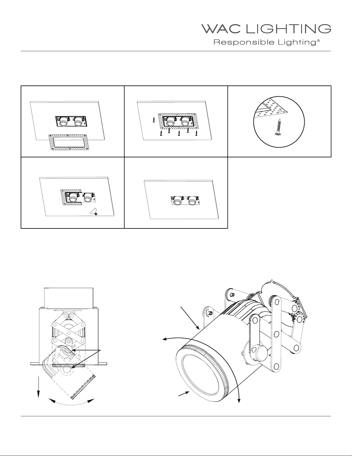
TRIMLESS INSTALLATION
1. Raise the trimless spackle frame to ceiling opening and secure with screws supplied (as Fig.15, Fig.16 and Fig.17).
2. Apply plaster or spackle over the trimless spackle frame and sand surface when dry for a nished look (as Fig.18 and Fig.19).
Fig. 15
Fig. 18
Fig. 16
Fig. 19
Fig. 17
FIXTURE AIMING AND BEAM ADJUSTMENT (BE SURE FIXTURE IS NOT HOT)
1. Pull down, twist, or rotate xture head to desired position. Tighten screw ‘A’ to lock position (Fig. 20)
2. Hold xture body with one hand and front cap with another. (Fig. 21)
3. Grip the front cap with two ngers and rotate it gently clockwise or counter clockwise until desired beam angle is achieved. (Fig. 21)
4. Cease rotation when you feel resistance as beam angle is reaching its minimum or maximum. (Fig. 21)
Fig. 20 Fig. 21
Fixture Body
Counter Clockwise
Increase Beam Angle
Screw A
Front Cap
waclighting.com
Phone (800) 526.2588
Fax (800) 526.2585
WAC Lighting retains the right to modify the design of our products at any time as part of the company's continuous improvement program. JULY, 2018
Headquarters/Eastern Distribution Center
44 Harbor Park Drive
Port Washington, NY 11050
Central Distribution Center
1600 Distribution Ct
Lithia Springs, GA 30122
Beam Angle
Adjustment
Clockwise
Decrease Beam Angle
Western Distribution Center
1750 Archibald Avenue
Ontario, CA 91760
5
Page 6
INSTALLATION INSTRUCTION
Silo Multiples - New Construction Housing
MT-4*15, MT-4*10
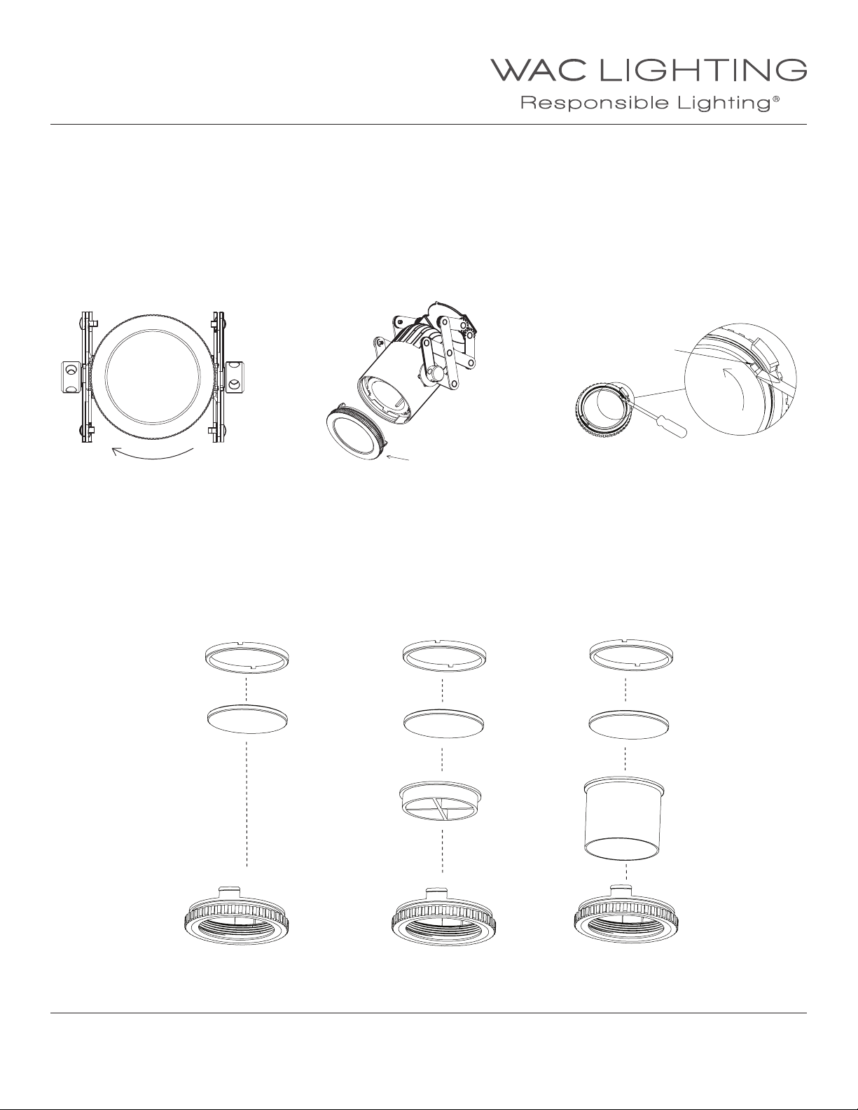
ACCESSORIES
1. With the xture powered o and front cap facing you, rotate the front cap clockwise just passed the position until you feel a “click” (Fig. 22)
2. Gently, while holding the xture body secure, rock the front cap assembly back and forth while pulling it away from the xture body to
remove front cap assembly. (Fig. 23)
3. Use a at-tip-screwdriver to remove the accessory holder by rotating it counter clockwise. (Fig. 24)
Fig. 22 Fig. 23
Front Cap Assembly
Rotate Clockwise
Fig. 24
Accessories Holder
Slot
4. Fixture accommodates one lens and one glare control accessory. (Refer to spec sheet for list of compatible accessories).
Install accessories between the front cap and accessory holder. Tighten accessory holder after accessories are installed. (Fig.25)
Fig. 25
Accessory Holder
Accessory Holder Accessory Holder
Front Cap
waclighting.com
Phone (800) 526.2588
Fax (800) 526.2585
WAC Lighting retains the right to modify the design of our products at any time as part of the company's continuous improvement program. JULY, 2018
LENS -16
LENS -16 LENS -16
LENS -16P - CRL
Front Cap Front Cap
Headquarters/Eastern Distribution Center
44 Harbor Park Drive
Port Washington, NY 11050
Central Distribution Center
1600 Distribution Ct
Lithia Springs, GA 30122
LENS -16 - SNOOT
Western Distribution Center
1750 Archibald Avenue
Ontario, CA 91760
6
Page 7
INSTALLATION INSTRUCTION
Silo Multiples - New Construction Housing
MT-4*15, MT-4*10
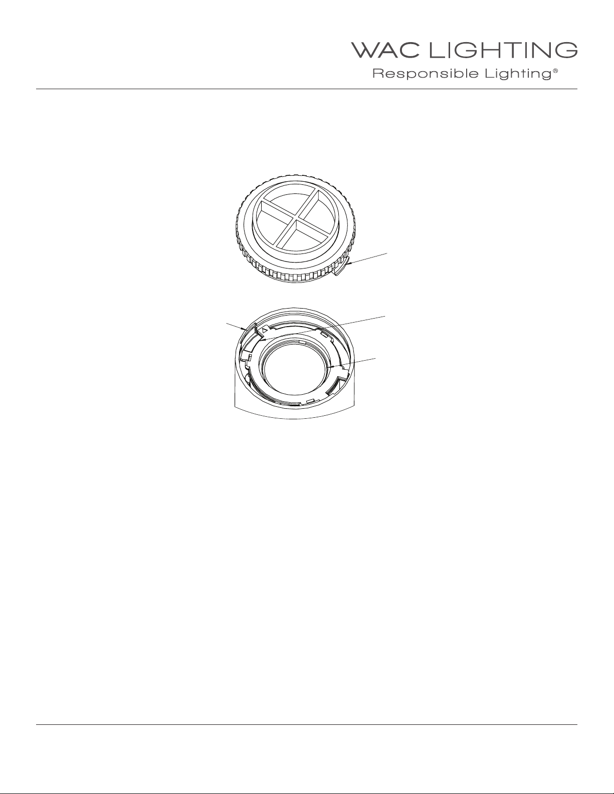
5. Ensure internal xture lens is still at the top position, and lens holder slots align with xture body slots. Align the front cap tabs with
the xture body slots and insert the front cap assembly back into the xture. Once fully inserted, rotate the front cap assembly counter
clockwise passed the “click” and to the desired beam angle. (Fig. 26)
Fig. 26
Front Cap Tabs
Fixture Body Slot
Lens Holder Slot
Internal Fixture Lens
positioned at top
waclighting.com
Phone (800) 526.2588
Fax (800) 526.2585
WAC Lighting retains the right to modify the design of our products at any time as part of the company's continuous improvement program. JULY, 2018
Headquarters/Eastern Distribution Center
44 Harbor Park Drive
Port Washington, NY 11050
Central Distribution Center
1600 Distribution Ct
Lithia Springs, GA 30122
Western Distribution Center
1750 Archibald Avenue
Ontario, CA 91760
7
 Loading...