

Page 1
INSTALLATION INSTRUCTION
Aether 3.5” Shallow Recessed Housing
HR-3LED-H17A
SAFETY INSTRUCTION
IMPORTANT: NEVER attempt any work without shutting o the electricity.
• Read all instructions before installing.
• System is intended for installation by a qualied electrician in accordance with the National Electrical Code and local regulations.
• Place the wall switch in the “OFF” position.
• Go to the main fuse box, or circuit breaker. Unscrew the fuse(s) or switch ”OFF” the circuit breaker switch(es) that control the power
to the space that you are working on.
CAUTION:
All parts must be used as indicated in these instructions. Do not substitute any parts, leave parts out, or use any parts that are worn out or
broken. Failure to follow this instruction could invalidate the ETL/cETL listing of this xture.
AVERTISSEMENT
IMPORTANT : COUPEZ L’ÉLECTRICITÉ AVANT TOUTE MANIPULATION.
• Lisez toutes les instructions avant d’installer.
• Système est destiné à être installé par un électricien qualié en conformité avec le code national de l’électricité et les règlements locaux.
• Placez l’interrupteur mural en position d’arrêt (« OFF »).
• Accédez au panneau central de disjoncteurs ou de fusibles de votre demeure et placez l’interrupteur principal en position d’arrêt (« OFF »).
MISE EN GARDE
Toutes les pièces doivent être utilisées tel qu’il est indiqué dans ces instructions. Ne remplacez pas les pièces, n’en laissez pas de côté et
ne les utilisez pas si elles sont usées ou brisées. Le non-respect de ces instructions peut annuler l’homologation ETL/cETL du luminaire.
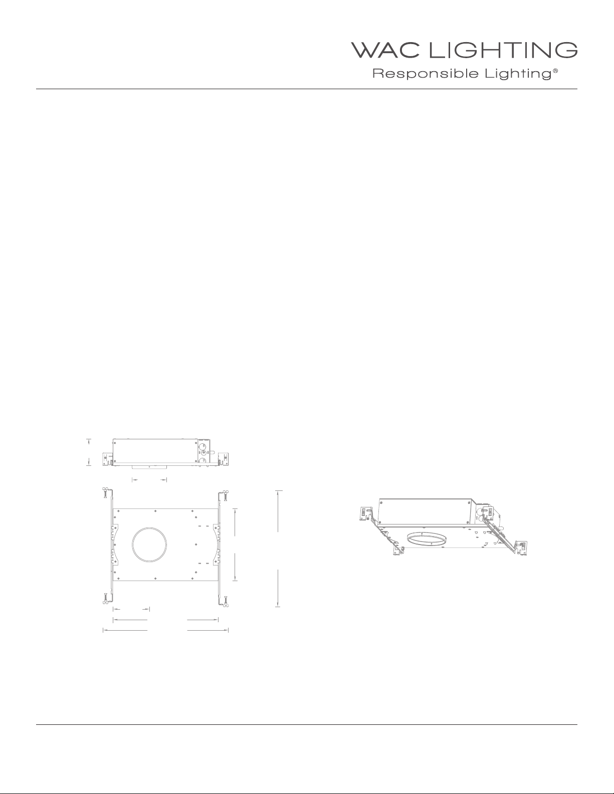
OVERVIEW:
This housing is new construction IC rated and AIRTIGHT. It requires a trim for nished look. Check our catalog or website for compatible trim
choices
32"
4s"
92" Min 142"
Max 212"
4w"
13d"
162"
WAC Lighting
www.waclighting.com
Phone (800) 526.2588 • Fax (800) 526.2585
WAC Lighting retains the right to modify the design of our products at any time as part of the company's continuous improvement program. MARCH 6, 2018 5:43 PM
Headquarters/Eastern Distribution Center
44 Harbor Park Drive • Port Washington, NY 11050
Phone (516) 515.5000 • Fax (516) 515.5050
1
Western Distribution Center
1750 Archibald Ave • Ontario, CA 91761
Phone (800) 526.2588 • Fax (800) 526.2585
Page 2
INSTALLATION INSTRUCTION
Aether 3.5” Shallow Recessed Housing
HR-3LED-H17A
HOUSING INSTALLATION:
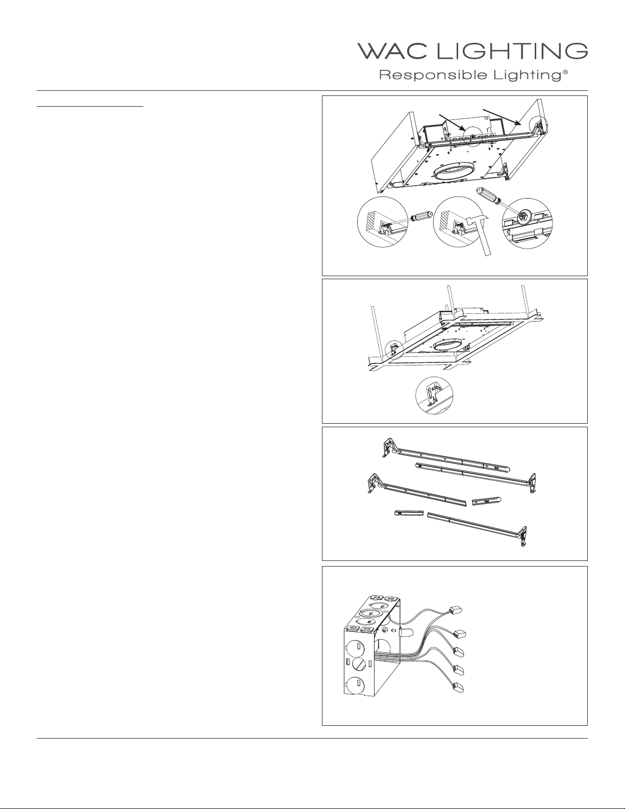
1. Install housing using two hanger bars provided. Align the bottom
of the hanger bar with the bottom of the joist. Secure the
“screw-nail” on each end by screw-driver or by hammer
(See FIG.1 detail A).
Slide xture along hanger bar into the desired location, use locking
screws to secure (See FIG.1 detail B).
For grid installation, hanger bars are supported on grids.
(See FIG.2)
FIG.1
FIG.2
B
A
A
B
2. To shorten hanger bars to t in a 12” joist, snap o one section of
the hanger bars (See FIG.3).
3. Remove spring latched junction box cover and connect xture
wires to building wires: insert each supply wire into appropriate
junction box connector. Connect black xture wire to hot, white
xture wire to neutral , green xture wire to ground, grey xture
wire to Dim (-) and purple xture wire to Dim (+) (See FIG.4).
To utilize ELV, wire black (line hot) and white (line neutral) in
accordance to dimmer specications. To utilize 0-10V dimming,
wire purple (dim+), gray (dim-), black (line hot), and white
(line neutral) in accordance to dimmer specications.
When not using a dimmer, connect black xture wire to hot, white
xture wire to neutral and green xture wire to ground. Leave all
other wires capped individually.
Place all wiring and connectors back in junction box and replace
the junction box’s cover.
FIG.3
Snap o one section t in a 12” joist
FIG.4
Green: ground
Black: hot
White: neutral
Grey : 0 - 10V Dim (-)
Purple : 0-10V Dim (+)
WAC Lighting
www.waclighting.com
Phone (800) 526.2588 • Fax (800) 526.2585
WAC Lighting retains the right to modify the design of our products at any time as part of the company's continuous improvement program. MARCH 6, 2018 5:43 PM
Headquarters/Eastern Distribution Center
44 Harbor Park Drive • Port Washington, NY 11050
Phone (516) 515.5000 • Fax (516) 515.5050
2
Western Distribution Center
1750 Archibald Ave • Ontario, CA 91761
Phone (800) 526.2588 • Fax (800) 526.2585
Page 3
INSTALLATION INSTRUCTION
Aether 3.5” Shallow Recessed Trims (Downlight)
R3ARDT, R3ASDT
DOWNLIGHT TRIM INSTALLATION
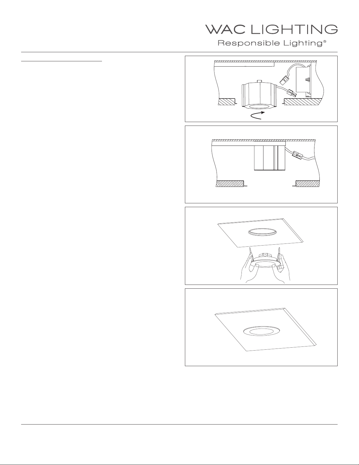
1. When installing in drywall, cut a hole 4 5/8” into it. Note: 1
1/2” inch maximum ceiling thickness.
2. Install light engine into the housing by rotating it clockwise
onto stud (Fig.1)
Connect light engine and housing power connectors (Fig.2).
3. Raise the trim to housing, depress trim spring clips and push
the trim assembly up until the trim ring is ush to the ceiling
(See FIG.3 and FIG.4).
FIG.1
FIG.2
FIG.3
FIG.4
WAC Lighting
www.waclighting.com
Phone (800) 526.2588 • Fax (800) 526.2585
WAC Lighting retains the right to modify the design of our products at any time as part of the company's continuous improvement program. MARCH 6, 2018 5:43 PM
Headquarters/Eastern Distribution Center
44 Harbor Park Drive • Port Washington, NY 11050
Phone (516) 515.5000 • Fax (516) 515.5050
3
Western Distribution Center
1750 Archibald Ave • Ontario, CA 91761
Phone (800) 526.2588 • Fax (800) 526.2585
Page 4
INSTALLATION INSTRUCTION
Aether 3.5” Shallow Recessed Trims (Adjustable)
R3ARAT, R3ASAT
ADJUSTABLE TRIM INSTALLATION
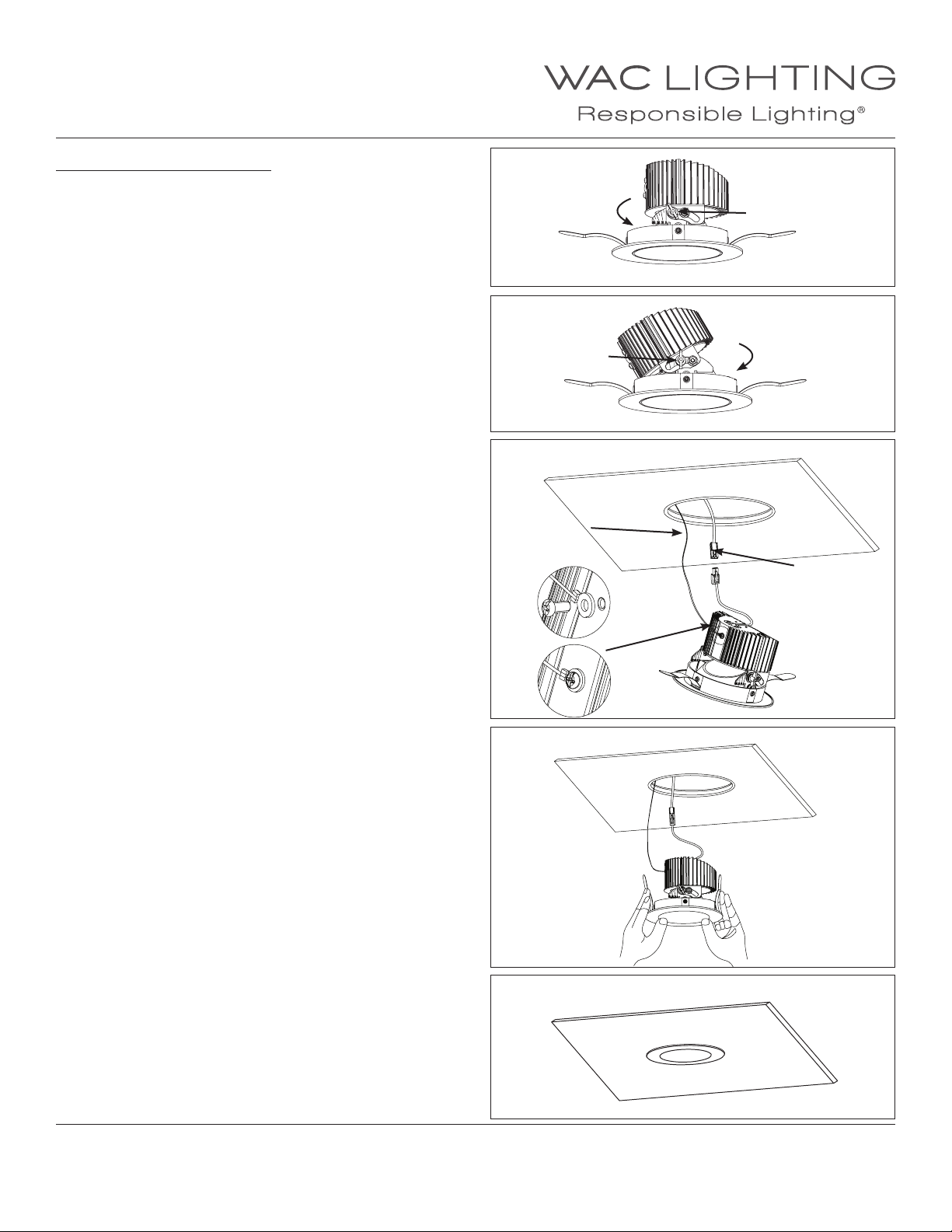
1. When installing in drywall, cut a hole 4 5/8” into it. Note: 1
1/2” inch maximum ceiling thickness.
2. Loosen the locking tab by rotating counter clockwise (Fig.1)
Adjust to desired angle (From 0°to 30°), Retighten the locking
tab (Fig.2).
3. Raise trim to ceiling and connect the power quick connector.
Secure safety cable to top of trim using screw provided
(Fig.3).
FIG.1
FIG.2
FIG.3
Safety cable
Loosen
Locking Tab
Locking Tab
Tighten
Power
Quick
Connector
4. Push the trim assembly up inside the housing until the trim
ring is ush to the ceiling (as Fig.4 and Fig.5).
WAC Lighting
www.waclighting.com
Phone (800) 526.2588 • Fax (800) 526.2585
Headquarters/Eastern Distribution Center
44 Harbor Park Drive • Port Washington, NY 11050
Phone (516) 515.5000 • Fax (516) 515.5050
FIG.4
FIG.5
Western Distribution Center
1750 Archibald Ave • Ontario, CA 91761
Phone (800) 526.2588 • Fax (800) 526.2585
WAC Lighting retains the right to modify the design of our products at any time as part of the company's continuous improvement program. MARCH 6, 2018 5:43 PM
4
Page 5
INSTALLATION INSTRUCTION
Aether 3.5” Shallow Recessed Trims (Wall Wash)
R3ARWT, R3ASWT
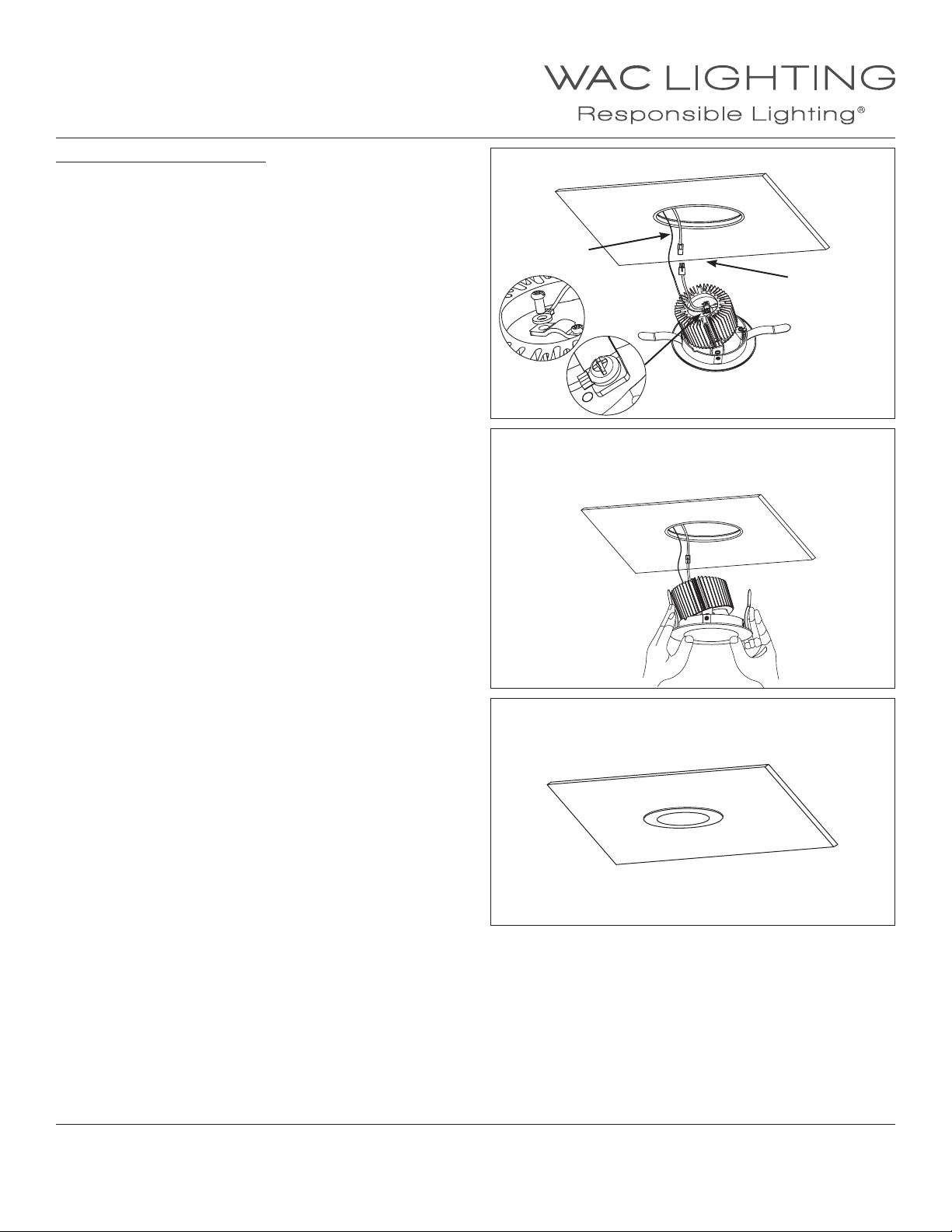
WALL WASH TRIM INSTALLATION
1. When installing in drywall, cut a hole 4 5/8” into it. Note: 1
1/2” inch maximum ceiling thickness.
2. Raise trim to ceiling and connect the power quick connector
secure safety cable to top of trim using screw provided
(as Fig.1).
3. Push the trim assembly up inside the housing until the trim
ring is ush to the ceiling (as Fig.2 and Fig.3).
FIG.1
Safety cable
Power
Quick
Connector
FIG.2
WAC Lighting
www.waclighting.com
Phone (800) 526.2588 • Fax (800) 526.2585
FIG.3
Headquarters/Eastern Distribution Center
44 Harbor Park Drive • Port Washington, NY 11050
Phone (516) 515.5000 • Fax (516) 515.5050
Western Distribution Center
1750 Archibald Ave • Ontario, CA 91761
Phone (800) 526.2588 • Fax (800) 526.2585
WAC Lighting retains the right to modify the design of our products at any time as part of the company's continuous improvement program. MARCH 6, 2018 5:43 PM
5
Page 6
INSTALLATION INSTRUCTION
Aether 3.5” Shallow Recessed Trimless
R3ARDL, R3ASDL
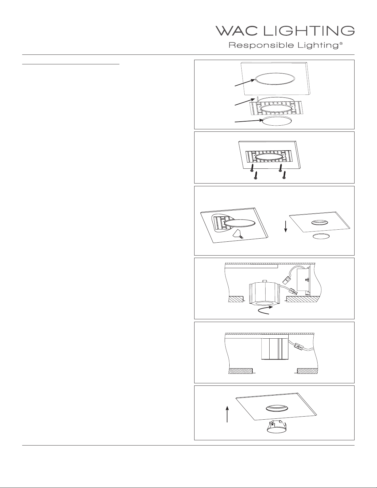
DOWNLIGHT TRIMLESS INSTALLATION
1. When installing in drywall, cut a hole 4 5/8” in the drywall.
Note: 1 1/2” inch maximum ceiling thickness.
2. Raise the trimless frame aligning tab to slot in housing,
and put plaster shield inside (See FIG.1).
3. Secure the trimless frame to the housing, ush up against the
ceiling using the screws supplied (See FIG.2).
4. Apply plaster or spackle over trimless frame and sand surface
when dry for a nished look ( See FIG.3).
FIG.1
Slot in housing
Tab
Plaster Shield
FIG.2
FIG.3 FIG.4
5. Remove the plaster cover when nishing is completed
(See FIG.4).
6. Install light engine into the housing by rotating it
clockwise onto stud (Fig.5)
Connect light engine and housing power connectors (Fig.6).
7. Raise the trimless assembly up to trim frame until the trim
ring is ush to the trim frame (See FIG.7).
Remove plaster shield
FIG.5
FIG.6
FIG.7
WAC Lighting
www.waclighting.com
Phone (800) 526.2588 • Fax (800) 526.2585
WAC Lighting retains the right to modify the design of our products at any time as part of the company's continuous improvement program. MARCH 6, 2018 5:43 PM
Headquarters/Eastern Distribution Center
44 Harbor Park Drive • Port Washington, NY 11050
Phone (516) 515.5000 • Fax (516) 515.5050
6
Western Distribution Center
1750 Archibald Ave • Ontario, CA 91761
Phone (800) 526.2588 • Fax (800) 526.2585
Page 7
INSTALLATION INSTRUCTION
Aether 3.5” Shallow Recessed Trimless
(Adjustable/Wall Wash - Round)
R3ARAL, R3ASAL, R3ARWL, R3ASWL
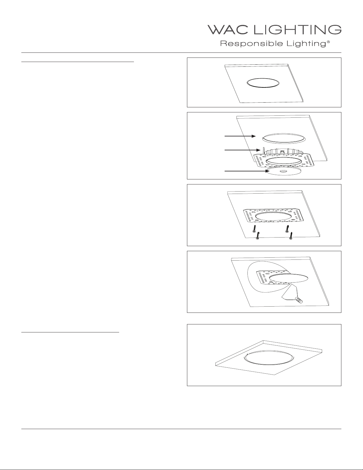
ROUND INVISIBLE TRIM FRAME INSTALLATION
1. When installing in drywall, cut a hole 4 3/4” into it
(See FIG.1).
Note: Accomodates 1 1/2” ceiling thickness.
2. Raise the trimless frame aligning tab to slot in housing, and put
shield inside (See FIG.2).
3. Secure the trimless frame to the housing, ush up against the ceiling using the screws supplied (See FIG.3).
FIG.1
FIG.2
Slot in housing
Tab
Plaster Shield
FIG.3
4. Apply plaster or spackle over trimless frame and sand surface
when dry for a nished look ( See FIG.4).
SQUARE TRIMLESS FRAME INSTALLATION
(FOR SQUARE ADJUSTABLE AND SQUARE WALL WASH)
5. When installing in drywall, cut a hole 4 3/4” into it
(See FIG.5).
Note: Accomodates for 1/2” - 1 1/2” ceiling thickness.
FIG.4
FIG.5
WAC Lighting
www.waclighting.com
Phone (800) 526.2588 • Fax (800) 526.2585
WAC Lighting retains the right to modify the design of our products at any time as part of the company's continuous improvement program. MARCH 6, 2018 5:43 PM
Headquarters/Eastern Distribution Center
44 Harbor Park Drive • Port Washington, NY 11050
Phone (516) 515.5000 • Fax (516) 515.5050
7
Western Distribution Center
1750 Archibald Ave • Ontario, CA 91761
Phone (800) 526.2588 • Fax (800) 526.2585
Page 8
INSTALLATION INSTRUCTION
Aether 3.5” Shallow Recessed Trimless
(Adjustable/Wall Wash - Square)
R3ARAL, R3ASAL, R3ARWL, R3ASWL
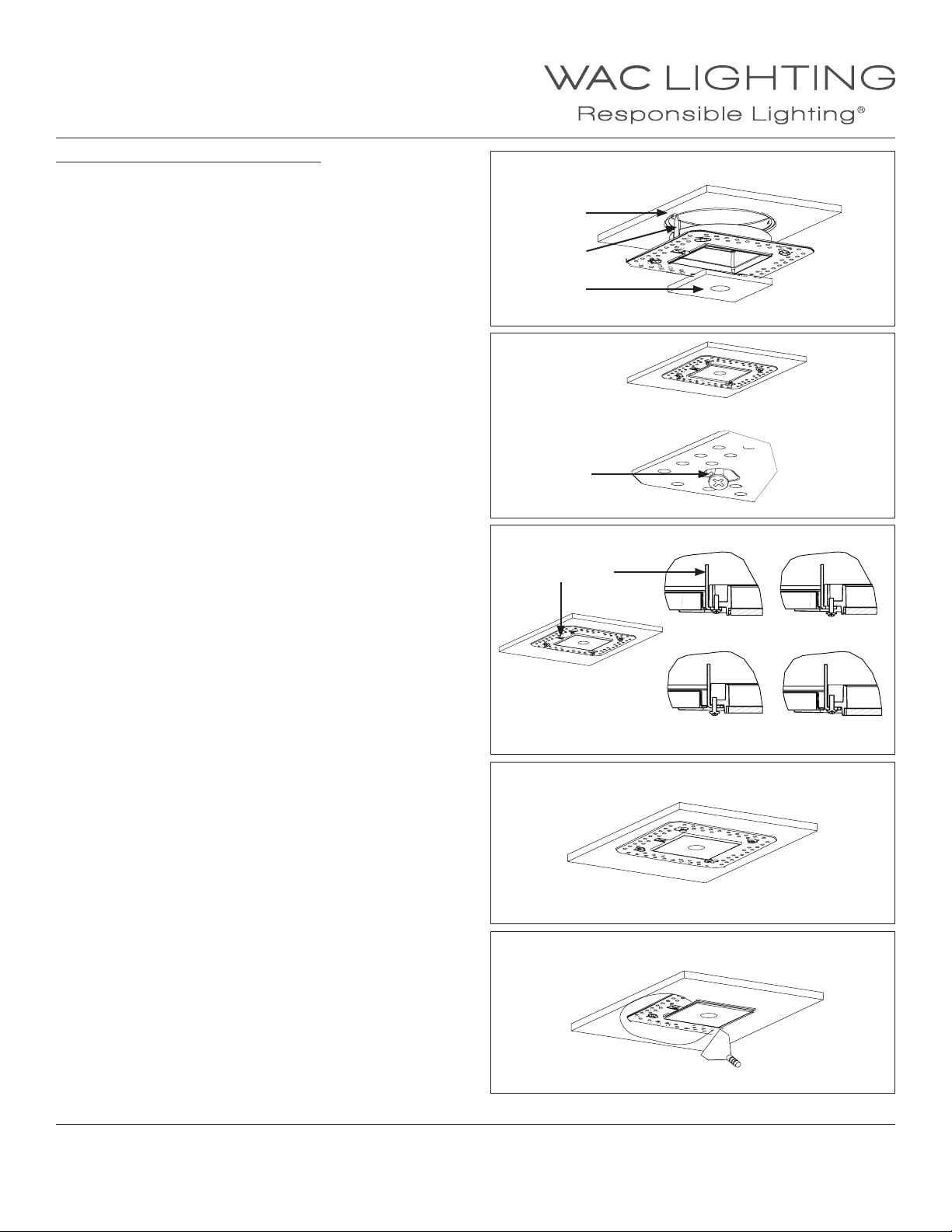
SQUARE TRIMLESS FRAME INSTALLATION
1. Raise the trimless frame aligning tab to slot in housing,
and put shield inside (See FIG.1).
2. Secure the trimless frame to the housing, lock the square trim
frame loosely in the slot with four self-tapping screws supplied.
(See FIG.2).
Note:The screws should pass through the holes in the housing.
3. Loosen the bae, move it to the inside(as the arrow shown),
then tighten it (See FIG.3).
FIG.1
Slot in housing
Tab
Plaster Shield
FIG.2
Slot
FIG.3
Bae
Initial state Loosen the screw
Move the bae Tighten the screw
4. Rotate the square trim frame to a correct position,
FIG.4
tighten the four self-tapping screws (See FIG.4).
5. Apply plaster or spackle over trimless frame and
FIG.5
sand surface when dry for a nished look (See FIG.5).
WAC Lighting
www.waclighting.com
Phone (800) 526.2588 • Fax (800) 526.2585
WAC Lighting retains the right to modify the design of our products at any time as part of the company's continuous improvement program. MARCH 6, 2018 5:43 PM
Headquarters/Eastern Distribution Center
44 Harbor Park Drive • Port Washington, NY 11050
Phone (516) 515.5000 • Fax (516) 515.5050
8
Western Distribution Center
1750 Archibald Ave • Ontario, CA 91761
Phone (800) 526.2588 • Fax (800) 526.2585
Page 9
INSTALLATION INSTRUCTION
Aether 3.5” Shallow Recessed Trimless Trims
Adjustable and Wall Wash
R3ARAL, R3ASAL, R3ARWL, R3ASWL
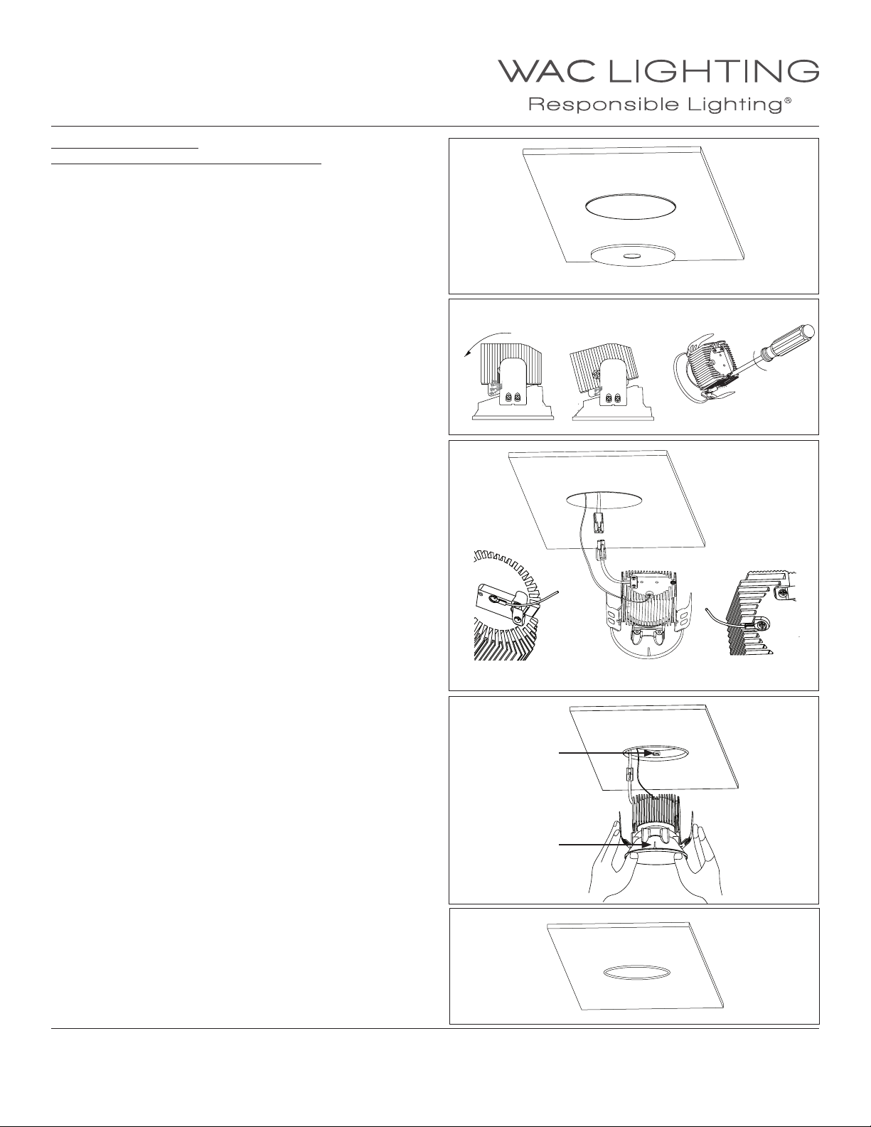
TRIMLESS INSTALLATION
(For Adjustable and Wall Wash, Round and Square )
1. Remove the plaster cover when nishing is completed (See FIG.1).
2. Set the angle between the trim and the heat sink.
Lock the screw in the top of the heat sink (See FIG.2).
Note:This step is just for the adjustable trim.
3. Raise trim to ceiling, contact the power quick connector and
locksafety cable to top of trim using screw provided (See FIG.3).
Note:The location of safety cable is dierent between adjustable
trim and wall wash trim as shown
FIG.1
Remove plaster shield
FIG.2
FIG.3
Wall Wash Adjustable
4. Raise the trimless assembly up to trim frame,
press the trim rings and push the trim until the trim
is ush to the trim frame (See FIG.4 and FIG.5).
Note: For of the hole in the trim frame (As the picture shown).
When you push the trim,the force pressed at the springs is
necessary or the springs may be damaged.
WAC Lighting
www.waclighting.com
Phone (800) 526.2588 • Fax (800) 526.2585
WAC Lighting retains the right to modify the design of our products at any time as part of the company's continuous improvement program. MARCH 6, 2018 5:43 PM
Headquarters/Eastern Distribution Center
44 Harbor Park Drive • Port Washington, NY 11050
Phone (516) 515.5000 • Fax (516) 515.5050
FIG.4
Hole
Rim
FIG.5
Western Distribution Center
1750 Archibald Ave • Ontario, CA 91761
Phone (800) 526.2588 • Fax (800) 526.2585
9
Page 10
INSTALLATION INSTRUCTION
Aether 3.5” Shallow Recessed
Driver Replacement
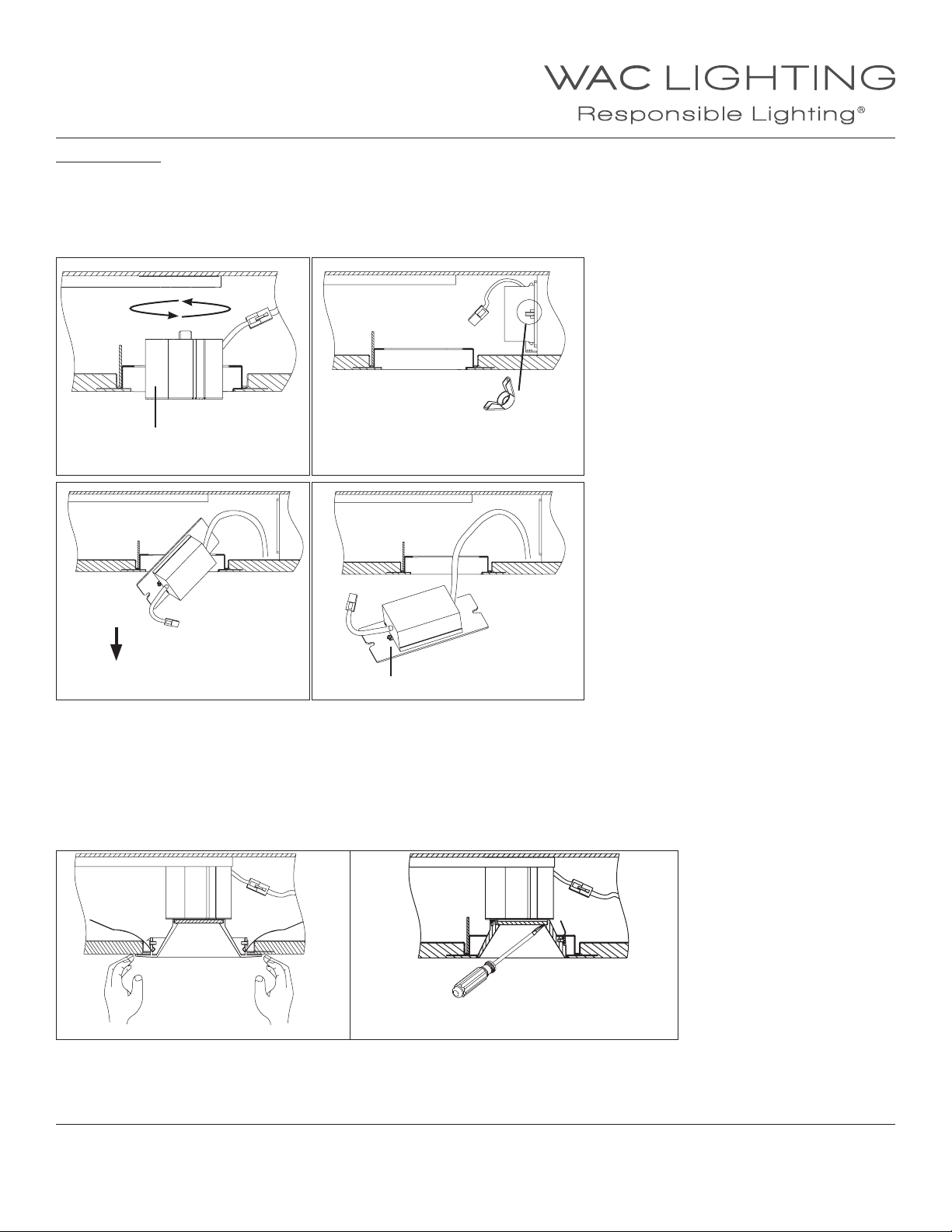
REPLACE DRIVER
1. Remove the LED module by rotating the LED module
counterclockwise and disconnect the LED module from the driver. (FIG.1) (Downlight Only), then loosen wing nuts on the side of driver
(FIG.2).
2. Tilt driver downward and remove from housing (FIG.3).
3. Remove screws to replace driver with new, rewire according to code and reinstall (FIG.4).
Wire
connector
Light engine
FIG.1
FIG.3 FIG.4
Wing Nuts
Screws
LED AND DRIVER REPLACEMENT
1. Remove the trim or trimless insert
a. Remove the trim or trimless insert as shown below (FIG.1 & 2).
To remove trimnless insert:
Remove the trimnless insert by gently prying
Remove the trim by pulling the trim’s edge
between the trimless bevel and lens
FIG.2
Trim Invisible Trim
WAC Lighting
www.waclighting.com
Phone (800) 526.2588 • Fax (800) 526.2585
WAC Lighting retains the right to modify the design of our products at any time as part of the company's continuous improvement program. MARCH 6, 2018 5:43 PM
FIG.1 FIG.2
Headquarters/Eastern Distribution Center
44 Harbor Park Drive • Port Washington, NY 11050
Phone (516) 515.5000 • Fax (516) 515.5050
10
Western Distribution Center
1750 Archibald Ave • Ontario, CA 91761
Phone (800) 526.2588 • Fax (800) 526.2585
Page 11
INSTALLATION INSTRUCTION
Aether 3.5” Shallow Recessed
LED Replacement - Trim
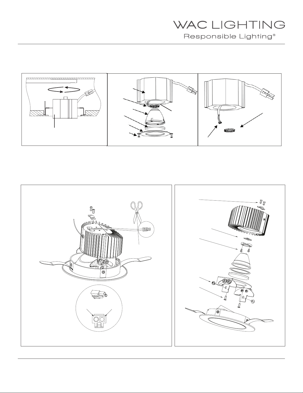
LED REPLACEMENT (DOWNLIGHT)
a. Disconnect wire connector, rotate the Light engine counterclockwise and pull out to remove the Light engine from housing (FIG.1).
b. Replace the LED by unscrewing the bracket, removing lens and reector. (FIG.2).
c. Remove existing thermal paste residue from heat sink. Apply new thermal paste (>3.15 w/m-k), then replace the LED (FIG.3).
Heat sink
Wire
connector
LED
Reector
Lens
Thermal Paste
Bracket
Light engine
FIG.1 FIG.2 FIG.3
Screws
Connector
LED REPLACEMENT (ADJUSTABLE AND WALL WASH TRIM)
1. Remove the trim by pulling the trim’s edge
2. Release the two screws from the light engine (FIG.1), remove the safety cable and use scissor to cut the LED input
3. Follow the steps (FIG.2) by removing #2, #3 then #4 screws from the light xture. Replace the LED module.
4. Remove existing thermal paste residue from heat sink. Apply new thermal paste (>3.15 W/M-K), then replace the LED Module.
1
LED
4
LED
2
3
Insert black wire (-)
to round input
Insert red wire (+)
to square input
FIG.1 FIG.2
WAC Lighting
www.waclighting.com
Phone (800) 526.2588 • Fax (800) 526.2585
WAC Lighting retains the right to modify the design of our products at any time as part of the company's continuous improvement program. MARCH 6, 2018 5:43 PM
Headquarters/Eastern Distribution Center
44 Harbor Park Drive • Port Washington, NY 11050
Phone (516) 515.5000 • Fax (516) 515.5050
11
Western Distribution Center
1750 Archibald Ave • Ontario, CA 91761
Phone (800) 526.2588 • Fax (800) 526.2585
Page 12
INSTALLATION INSTRUCTION
Aether 3.5” Shallow Recessed
LED Replacement - Invisible Trim
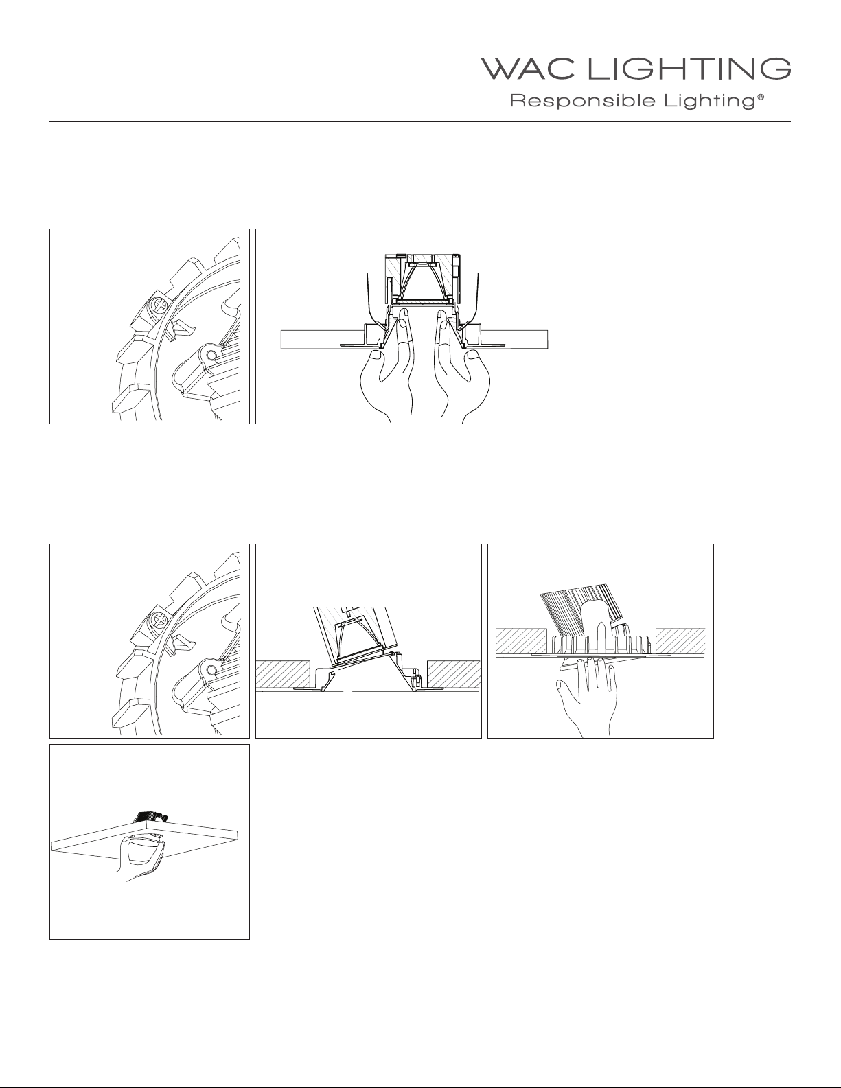
LED REPLACEMENT
1. Remove the invisible trim
1-1. Remove adjustable trim
a. Rotate the round trim to the position as shown (FIG.1) Note: The square trim doesn’t need this action
b. Remove the adjustable trim by pulling the edges of the trim (FIG.2)
FIG.1
1-2. Remove wall wash trim
a. Rotate the round trim to the position as shown (FIG.3) Note: The square trim doesn’t need this action
b. Remove the adjustable trim by pulling the edges of the trim (FIG.4)
c. Pull the other side of the trim (FIG.5)
d. Pull out the trim (FIG.6)
FIG.3
FIG.2
FIG.4 FIG.5
FIG.6
WAC Lighting
www.waclighting.com
Phone (800) 526.2588 • Fax (800) 526.2585
WAC Lighting retains the right to modify the design of our products at any time as part of the company's continuous improvement program. MARCH 6, 2018 5:43 PM
Headquarters/Eastern Distribution Center
44 Harbor Park Drive • Port Washington, NY 11050
Phone (516) 515.5000 • Fax (516) 515.5050
12
Western Distribution Center
1750 Archibald Ave • Ontario, CA 91761
Phone (800) 526.2588 • Fax (800) 526.2585
Page 13
INSTALLATION INSTRUCTION
Aether 3.5” Shallow Recessed
LED Replacement (Adjustable and Wall Wash Trim)
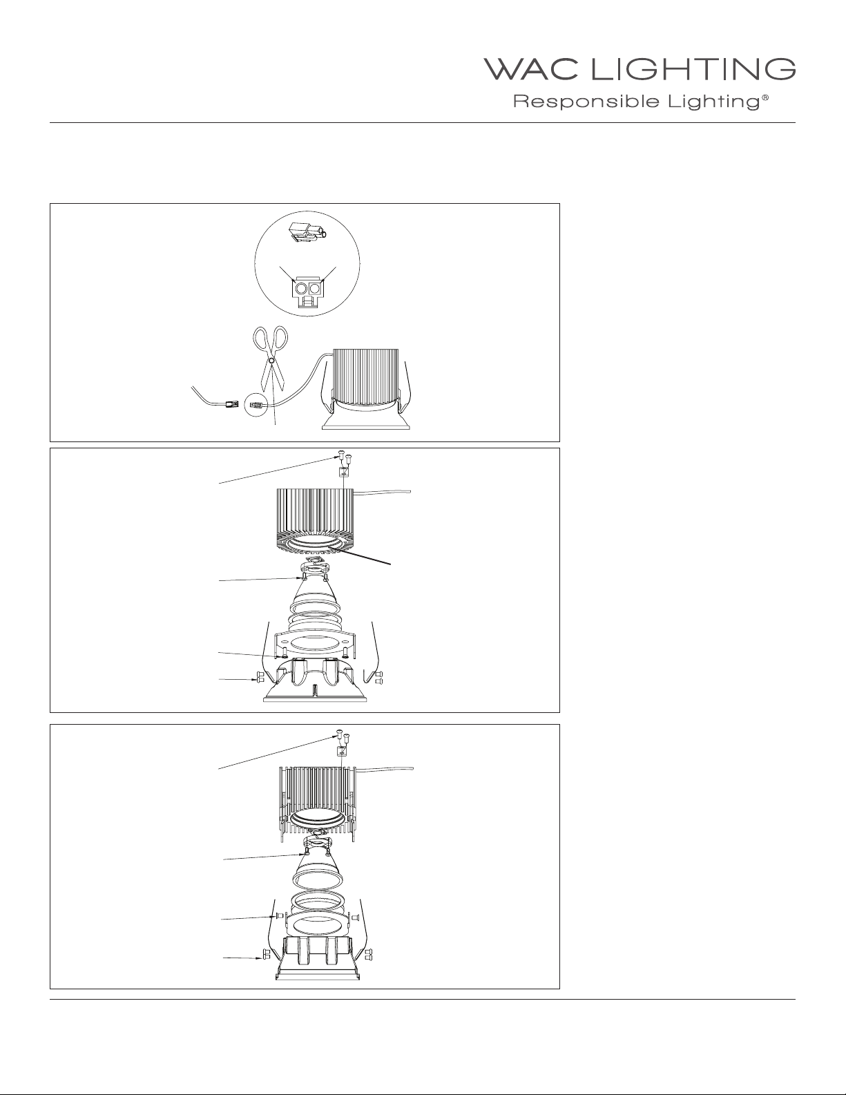
LED REPLACEMENT
1. Disconnect wire connector, use scissors to cut the LED input and release the screw from the heat sink to remove the safety cable (FIG.1).
2. Follow the steps (FIG.2 and FIG.3) by removing #1, #2, #3 and #4 screws from the light xture. Remove the existing LED module.
3. Replace existing thermal paste residue from heat sink. Apply newthermal paste (> 3.15 W/M-K), then replace the LED module.
FIG.1
FIG.2
Insert black wire (-)
to round input
1
4
Insert red wire (+)
to square input
Thermal Paste
3
2
FIG.3
1
4
3
2
WAC Lighting
www.waclighting.com
Phone (800) 526.2588 • Fax (800) 526.2585
Wall Wash
Adjustable
Headquarters/Eastern Distribution Center
44 Harbor Park Drive • Port Washington, NY 11050
Phone (516) 515.5000 • Fax (516) 515.5050
Western Distribution Center
1750 Archibald Ave • Ontario, CA 91761
Phone (800) 526.2588 • Fax (800) 526.2585
WAC Lighting retains the right to modify the design of our products at any time as part of the company's continuous improvement program. MARCH 6, 2018 5:43 PM
13
 Loading...