

Page 1
waclighting.com
Phone (800) 526.2588
Fax (800) 526.2585
Headquarters/Eastern Distribution Center
44 Harbor Park Drive
Port Washington, NY 11050
Central Distribution Center
1600 Distribution Ct
Lithia Springs, GA 30122
Western Distribution Center
1750 Archibald Avenue
Ontario, CA 91760
INSTALLATION INSTRUCTION
ROUND
FM-07RN, FM-11RN, FM-15RN
WARNING
IMPORTANT: NEVER attempt any work without shutting o the electricity.
- Read all instructions before installing.
- System is intended for installation by a qualied electrician in accordance with the National Electrical Code and local regulations.
- Go to the main fuse box, or circuit breaker. Place the main power switch in the “OFF” position and unscrew the fuse(s) or
switch ”OFF” the circuit breaker switch(es) that control the power to the xture or room that you are working on.
- Place the wall switch in the “OFF” position.
- Supply conductors (Power Wires) Connecting the xture must be rated minimum 90°C. If uncertain, consult an electrician.
CAUTIONS
- These luminaires (xtures) are designed to meet the latest NEC requirements and are listed in full compliance with UL 1598.
- Before attempting installation, check your local electrical code, as it sets the wiring standards for your locality.
INCLUDED ACCESSORIES BAG
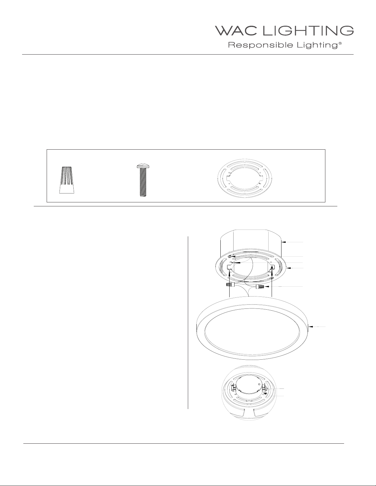
Wire Connector
Qty: 3 pcs
P3
Junction Box Screw
Qty: 2 pcs
#8-32, * 3/4”
Stainless Steel
INSTALLATION FOR FM-07RN AND FM-11RN
Uses 3” junction box, 4" junction box or a combination
3/0-4/0 electrical box.
1.
Install the provided mounting plate to the junction box using
the junction box screws provided.
2. Provide electrical service according to the “National Electrical
Code” or your local electrical code to the outlet box.
Clip the retention cable into the retention cable slot
3.
on the mounting plate to assist with wiring.
4. Connect supply wires to fixture wires and insulate with
proper wire nuts:
Connect incoming ground wire to mounting plate ground wire
(green or bare).
Connect incoming common wire to xture common (white).
Connect incoming hot wire to xture black wire.
Mounting Plate
Qty: 1 pc
3", 4" or 3/0-4/0 electrical
box, (by others)
Junction Box Mounting Screw
Retention Cable Slot
Mounting Plate
Wire Connector
Fixture
Fig. 1
5.
Raise the fixture to the junction box, guide the spring clips into
the slots in the mounting plate and press the front of the
fixture firmly at the clip locations to lock the fixture in place.
Note: To ensure an easier installation, press one side of the
fixture in first until you hear a click, then repeat with the other
side.
WAC Lighting retains the right to modify the design of our products at any time as part of the company's continuous improvement program. Dec 2017 1
Fig. 2 (back of the fixture once clipped into the mounting plate)
Spring Clip
Spring Clip Slot
Page 2
waclighting.com
Phone (800) 526.2588
Fax (800) 526.2585
Headquarters/Eastern Distribution Center
44 Harbor Park Drive
Port Washington, NY 11050
Central Distribution Center
1600 Distribution Ct
Lithia Springs, GA 30122
Western Distribution Center
1750 Archibald Avenue
Ontario, CA 91760
INSTALLATION INSTRUCTION
ROUND
FM-07RN, FM-11RN, FM-15RN
INSTALLATION FOR FM-15RN
Uses 3” junction box, 4" junction box or a combination
3/0-4/0 electrical box.
1.
Provide electrical service according to the “National Electrical
Code” or your local electrical code to the outlet box.
2.
Remove the mounting plate from the rest of the fixture
by rotating it counter clockwise. Disconnect the quick
connect cable between the mounting plate and the
fixture.
Connect supply wires to input wires on the mounting
3.
plate and insulate with proper wire nuts:
Connect incoming ground wire to mounting plate ground wire
(green or bare).
Connect incoming common wire to xture common (white).
Connect incoming hot wire to xture black wire.
4.
Install the provided mounting plate to the junction
box using the junction box screws provided.
Note: To guarantee a secure installation of the
mounting plate, please fasten additional screws (that
are appropriate for your mounting surface) to tighten
the mounting plate directly to the mounting surface.
Clip the retention cable into the retention cable slot
5.
on the mounting plate.
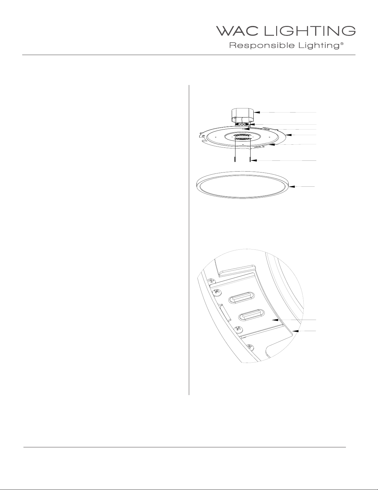
3", 4" or 3/0-4/0 electrical
box, (by others)
Wire Connector
Surface Mount Screw Holes
Mounting Plate
Clip Slot
Junction Box Mounting
Screw
Fixture
Fig. 3
Reconnect the quick connect cables between the
6.
mounting plate and fixture. Push the wires and
connector into the junction box through semicircle opening on the mounting plate.
Raise the fixture to mounting plate and guide the
7.
metal clips through the slots in the mounting
plate until the fixture if flush with the mounting
surface.
Rotate the fixture clockwise until fully tightened
8.
with the mounting surface.
WAC Lighting retains the right to modify the design of our products at any time as part of the company's continuous improvement program. Dec 2017
Metal Clip
Clip Slot
Fig. 4
2
 Loading...