

Page 1
INSTALLATION INSTRUCTION
AC-LED LEDme® Light Bars
BA-ACLED8, BA-ACLED12, BA-ACLED18, BA-ACLED24, BA-ACLED30, BA-ACLED36, BA-ACLED42
WARNING
IMPORTANT: NEVER attempt any work without shutting o the electricity.
• Read all instructions before installing.
• System is intended for installation by a qualied electrician in accordance with the National Electrical Code and local
regulations.
• Go to the main fuse box, or circuit breaker. Place the main power switch in the “OFF” position and unscrew the fuse(s) or
switch “OFF” the circuit breaker switch(es) that control the power to the xture or room that you are working on.
• Place the wall switch in the “OFF” position.
ADVERTISSEMENT
IMPORTANT: Coupez l’électricité avant TOUTE manipulation.
• Lisez toutes les instructions avant d’installer.
• Système est destiné à être installé par un électricien qualié en conformité avec le code national de l’électricité et
les règlements locaux.
• Accédez au panneau central de disjoncteurs ou de fusibles de votre demeure et placez l’interrupteur principal en
position d’arrêt (« OFF »).
• Placez l’interrupteur mural en position d’arrêt (« OFF »).
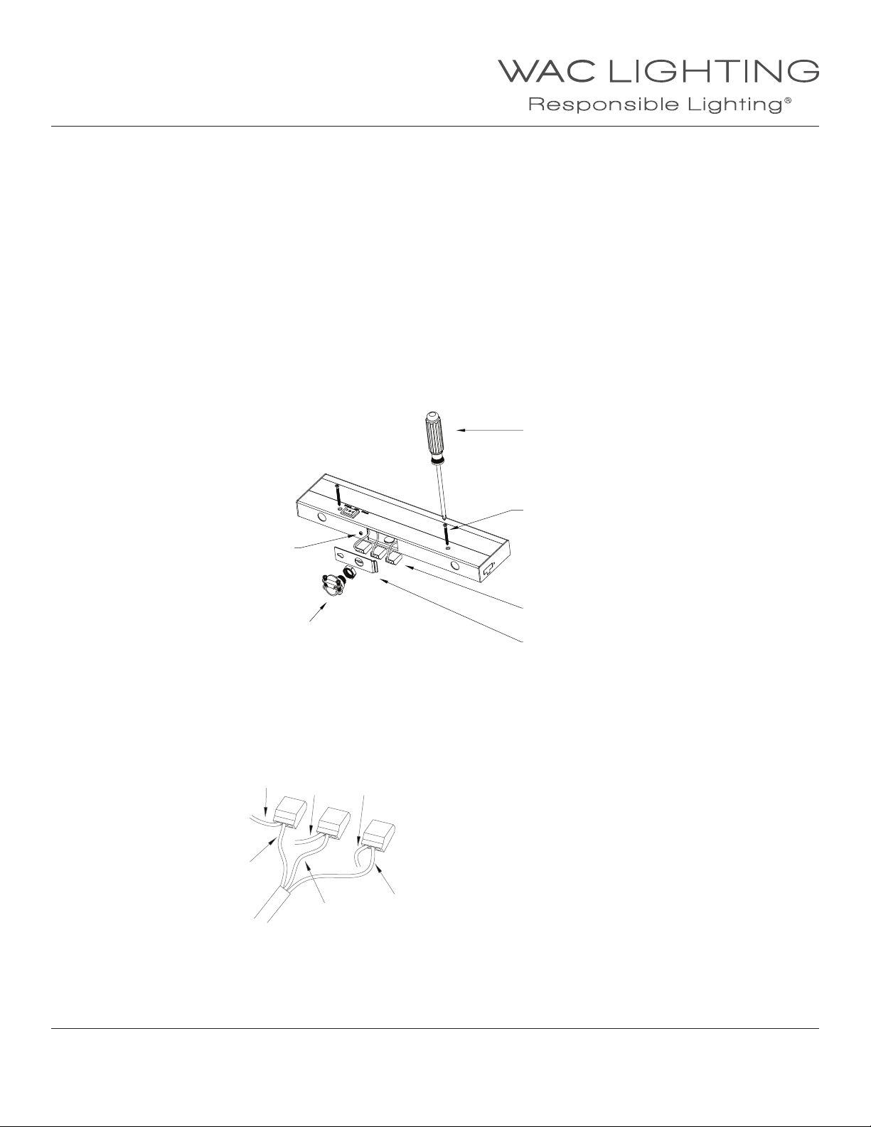
Fig.1 Installation and Wiring
(BA-ACLED12)
Round Screw
Non-metallic Sheathed Cable
Screw Driver
Mounting Screw
Poke-home Connector
Side Door
WIRING AND INSTALLATION
1. Pry open the knock out hole on the side door to install the input wires.
2. Unscrew round screw and remove the side door from window by sliding it to the side.
3. Install the Non-metallic sheathed cable/BX connector into the side door.
4. Push 120V input wires through the Non-metallic sheathed cable.
5. Strip 3/8” insulation o 120V input wires. Connect input wires to LED light bars using convenient “poke-home” connectors provided with
LED light bars. Push 120V input wires rmly into “poke-home” connectors for secure connections.
Fig.2 Input Wire
White
Green
Black
Connect black input wire to black xture wire.
Connect white input wire to white xture wire.
Connect green ground wire (may be bare copper)
to green xture wire.
White
Green
Black
6. Tuck wires connections neatly into LED light bar.
7. Install the side door onto xture and tighten round screw.
8. Take out two mounting screws from the package.
9. Screw the mounting screws through holes on the xture.
10. Place xture in appropriate place and tighten mounting screws.
WAC Lighting
www.waclighting.com
Phone (800) 526.2588 • Fax (800) 526.2585
WAC Lighting retains the right to modify the design of our products at any time as part of the company's continuous improvement program. JAN 2018
Headquarters/Eastern Distribution Center
44 Harbor Park Drive • Port Washington, NY 11050
Phone (516) 515.5000 • Fax (516) 515.5050
Western Distribution Center
1750 Archibald Ave • Ontario, CA 91761
Phone (800) 526.2588 • Fax (800) 526.2585
Page 2
INSTALLATION INSTRUCTION
AC-LED LEDme® Light Bars
BA-ACLED8, BA-ACLED12, BA-ACLED18, BA-ACLED24, BA-ACLED30, BA-ACLED36, BA-ACLED42
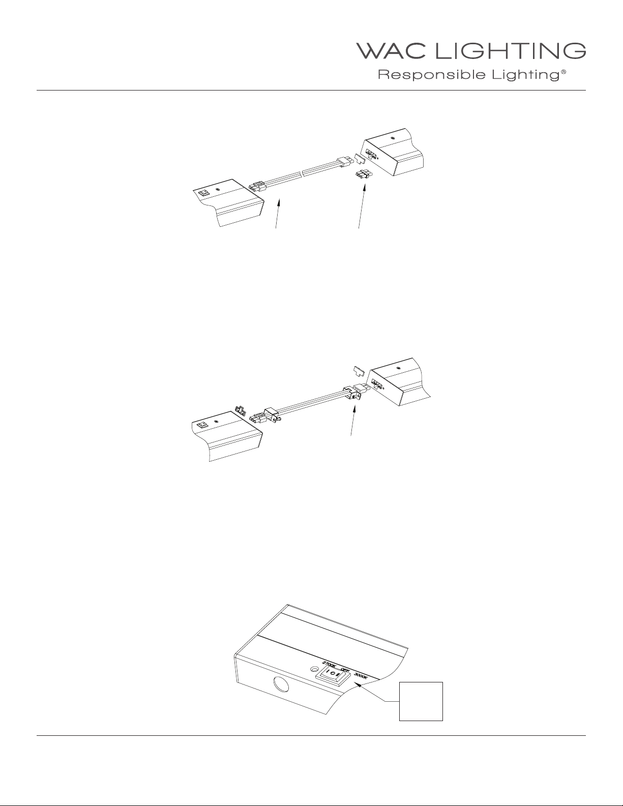
WIRING MULTIPLE UNITS:
In addition to hard wiring multiple xtures, components are provided to allow xtures to be linked through surface wiring.
Jumper Wire
I-Connector
a. End to End Connection with I-Connector (One included with each light bar):
The I-Connector allows two xtures to be connected end to end. I-Connector has one square and two round pins to
ensure the correct orientation.
NOTE: The total number of all connected xtures should not exceed 6 pieces for BA-I.
1. Pry out the plastic covers concealing the female connection ports at the end of the xtures.
2. Insert one end of the “I” connector into the rst xture. Slide the second xture into the rst one.
3. Secure the position of the second xture by using two mounting screws.
Cover Bracket
b. Connection with interconnect cable (Sold Separately):
A jumper wire allows multiple units to be linked through surface wiring.
The jumper wire has one square and two round pins to ensure the correct orientation.
NOTE: The total number of all connected xtures should not exceed 4 pieces for BA-IC12, BA-IC24. 3 pieces for BA-IC36
1. Pry out the plastic covers concealing the female connection ports at the end of the xtures.
2. Insert the ends of the connectors into each xture.
3. Jumper wires have metal strain relief cover brackets. Slide the cover bracket over the connector. Position the bracket so that the hole
in the bracket aligns with the hole in the xture. Use the screw supplied to secure the cover bracket to the xture.
4. Wrap excess wires using wire ties if necessary.
CCT SWITCHING OPTION
Fixture’s CCT can be set to 2700K or 3000K by
pressing the switch on the xture as shown:
WAC Lighting
www.waclighting.com
Phone (800) 526.2588 • Fax (800) 526.2585
WAC Lighting retains the right to modify the design of our products at any time as part of the company's continuous improvement program. JAN 2018
Headquarters/Eastern Distribution Center
44 Harbor Park Drive • Port Washington, NY 11050
Phone (516) 515.5000 • Fax (516) 515.5050
I : 2700K
O: OFF
II : 3000K
Western Distribution Center
1750 Archibald Ave • Ontario, CA 91761
Phone (800) 526.2588 • Fax (800) 526.2585
 Loading...