

Page 1
INSTALLATION INSTRUCTION
300 Series LED Quick Connect™ Socket Set
QP-LED303, MP-LED303
OVERVIEW:
Socket Set LED303 is designed for use with WAC MP-60E and
all WAC quick connect canopies. Model MP-LED303 uses the same
socket set as Model QP-LED303 except for QP-LED303 with
a quick connector.
Model MP-LED303 is use with WAC power unit MP-60E.
Model QP-LED303 is use with WAC the quick connect adapters:
Solorail™ (LM), Duorail™ (LM2), Canopies (QMP),
Line Voltage Tracks (H, J, L), Flexrail1™ (HM1)
QUICK CONNECT™ ADAPTER (order separately)
Solorail (LM) Adapter: LM-QADP
Duorail (LM) Adapter: LM2-QADP
Flexrail1 (HM1) Adapter: HM1-EN50
Line Voltage Track (H, J, L) Adapter:
EN-HQ50AR, EN-JQ50AR, EN-LQ50AR
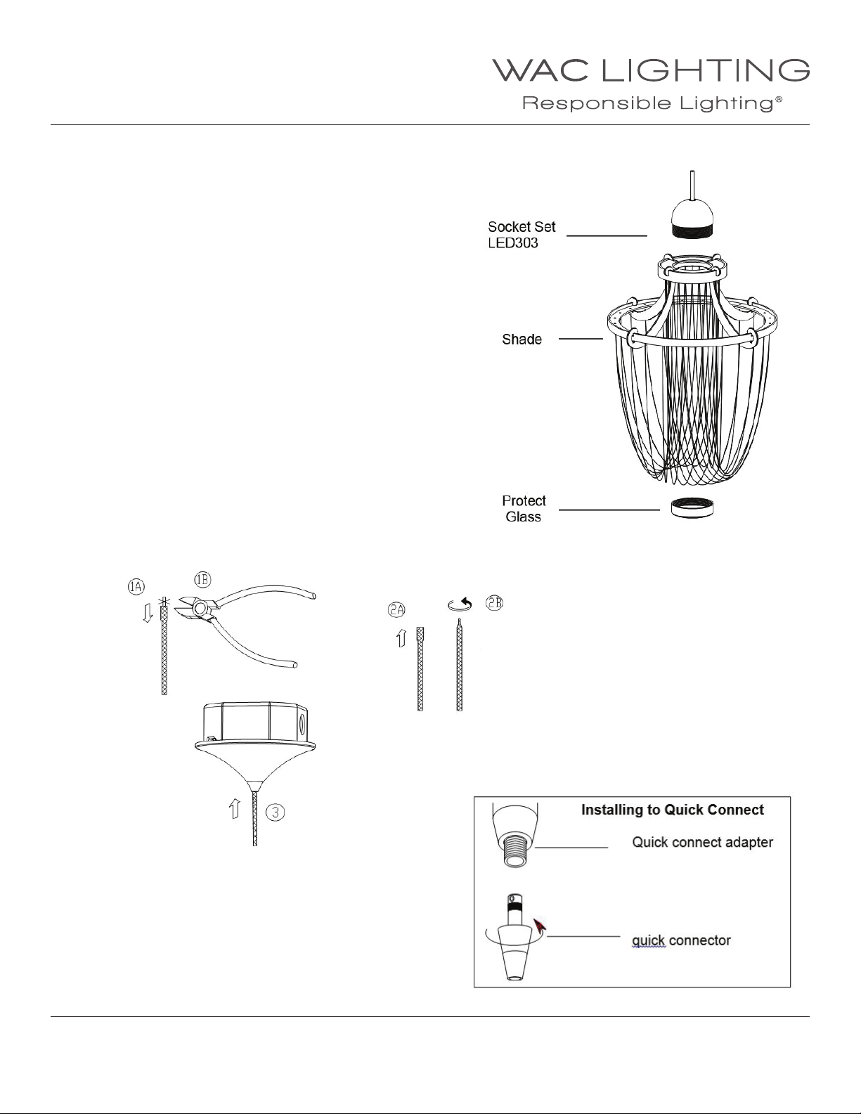
INSTALLING SHADE:
Position Socket Set LED303 so that threads through the hole in the
shade and screw on Ring from below by nger or Ring Tool.
(See diagram).
For model MPLED303:
Put the knitted cable from the Socket Set into
the cable grip (according to the steps 1,2,3, shown
in the picture below)
Put the cable into
the MP-60E
For model QPLED303:
1. Insert the post of the quick connect into the
quick connect adapter.
2. Thread the top half of the conical section until it is ush
with the adapter.
3. Adjust xture position, but use caution not to loosen
the conical section.
Twist the cable
with pliers
WAC Lighting
www.waclighting.com
Phone (800) 526.2588 • Fax (800) 526.2585
WAC Lighting retains the right to modify the design of our products at any time as part of the company's continuous improvement program. JULY, 2014
Headquarters/Eastern Distribution Center
44 Harbor Park Drive • Port Washington, NY 11050
Phone (516) 515.5000 • Fax (516) 515.5050
Western Distribution Center
1750 Archibald Ave • Ontario, CA 91761
Phone (800) 526.2588 • Fax (800) 526.2585
Page 2
INSTALLATION INSTRUCTION
300 Series LED Quick Connect™ Socket Set
QP-LED303, MP-LED303
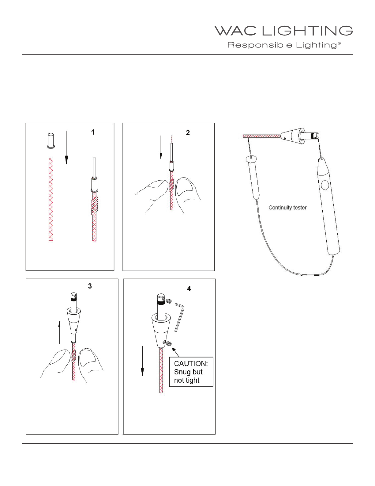
TO INSTALL / SHORTEN THE CABLE:
Feed the cable end through the Top Conical section and the metal nial. If cable needs to be shortened, make the cut now.
To install the top conical section, follow the step-by-step instructions bellow. NOTE: PENDANT CABLES ARE COAXIAL, IF THE
LOWER SCREW IN STEP 4 IS MADE TOO TIGHT, THE INNER AN OUTER WIRE WILL SHORT. A SHORT CIRCUIT WILL
RENDER THE ENTIRE SYSTEM INOPERATIVE AND POSSIBLY DAMAGE THE TRANSFORMER. CHECK ALL PENDANT
SPLICES FOR CONTINUITY BEFORE INSTALLING.
Make a clean cut. Slide brass
collar over wire.
Feed inner wire until it reaches
the top set screw position.
Feed braided outer wire and
collar into bottom portion.
Trim 1/8” of insulation from the
inner wire. Position the collar so
that a small section (1/16”) of
braided wire protrudes from the
top of the collar.
CHECK SPLICE:
There should now be continuity, indicating
a completed circuit.
Install with power o.
Tighten top setscrew rst then
lower. Smooth out any bulges in
braided wire. Perform continuity
check before mounting.
WAC Lighting
www.waclighting.com
Phone (800) 526.2588 • Fax (800) 526.2585
WAC Lighting retains the right to modify the design of our products at any time as part of the company's continuous improvement program. JULY, 2014
Headquarters/Eastern Distribution Center
44 Harbor Park Drive • Port Washington, NY 11050
Phone (516) 515.5000 • Fax (516) 515.5050
Western Distribution Center
1750 Archibald Ave • Ontario, CA 91761
Phone (800) 526.2588 • Fax (800) 526.2585
Page 3
INSTALLATION INSTRUCTION
Quick Adjust™ Pendant Canopy
MP-60E
SAFETY INSTRUCTION
• Do not conceal or extend exposed conductors through a building wall.
• Do not install this system in wet locations.
• To reduce the risk of re and burns, do not install this lighting system where the exposed bare conductors can be shorted or
contact any conductive materials.
• Make sure all connections are tight.
• Do not install any luminaire closer than 6 inches from any curtain, or similar combustible materials.
• Turn o electrical power before modifying the lighting system in any way.
• Install over a standard 4 inch junction box.
OVERVIEW
MP-60E canopy designed to t all WAC Pendants. Uses a 50 watt max halogen lamp.
The pendant weight should be no more than 5 pounds. MP-60E canopy comes with a self-contained electronic transformer that
may be dimmed with an electronic low voltage dimmer switch.
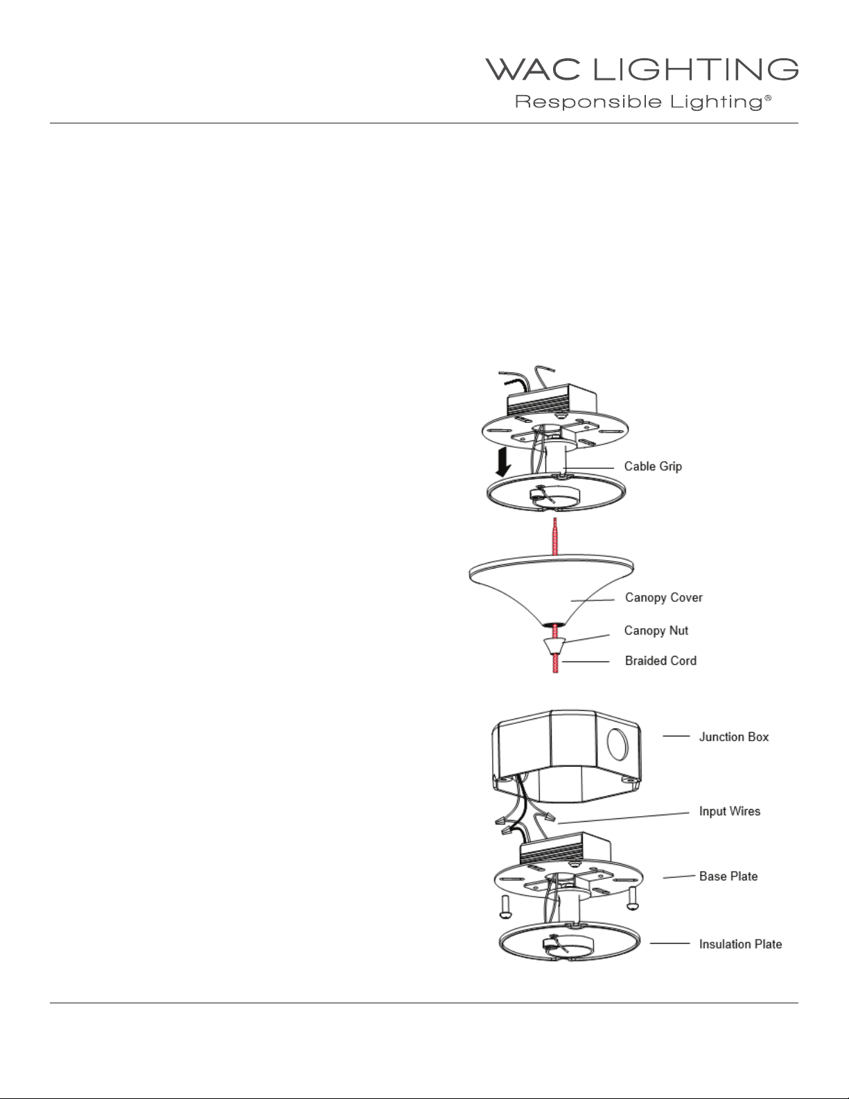
1. Unscrew “canopy nut” and remove “canopy cover”
from the threaded cable grip.
2. Pull down the “insulation plate”.
3. Support canopy and guide the black and white
wires from the transformer into the junction box.
4. Connect ground wire from junction box to the
green grounding wire from the base plate.
5. Connect corresponding line volt wires from the
junction box to transformer wires (white wire connect
to white wire and black wire connect to black wire),
with wire nuts (supplied). Tuck excess wire into the junction box.
6. Attach the “base plate” to the junction box using
the slotted holes and screws.
7. Re-attach “insulation plate”.
WAC Lighting
www.waclighting.com
Phone (800) 526.2588 • Fax (800) 526.2585
WAC Lighting retains the right to modify the design of our products at any time as part of the company's continuous improvement program. JUNE, 2014
Headquarters/Eastern Distribution Center
44 Harbor Park Drive • Port Washington, NY 11050
Phone (516) 515.5000 • Fax (516) 515.5050
Western Distribution Center
1750 Archibald Ave • Ontario, CA 91761
Phone (800) 526.2588 • Fax (800) 526.2585
Page 4
INSTALLATION INSTRUCTION
Quick Adjust™ Pendant Canopy
MP-60E
PENDANT INSTALLATION
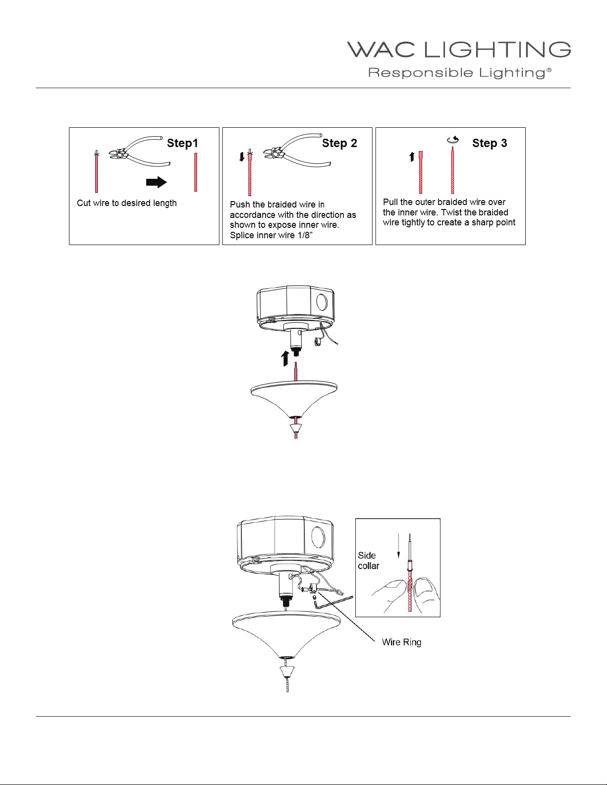
1. Make the desired cut of the “braided cord” for proper mounting height. Trim 1/8” of insulation from the inner wire.
2. Feed the “braided cord” through “canopy nut” and “canopy cover”. Push up the “cable grip” top and feed the braided cord until
3” braided cord comes out from side hole.
3. Position the “side collar” (supplied) so that a small section (1/16”) of “braided cord” protrudes from the top of the collar.
4. Feed the “braided cord” and “side collar” into the end of the “wire ring” and tighten the set screw with allen wrench (supplied).
5. Use wire nuts (supplied) to connect the protruding braid cord to the wire coming from the transformer.
6. Raise the “canopy cover” and make sure that wires are contained in the “canopy cover”.
7. Tighten “canopy nut ”.
WAC Lighting
www.waclighting.com
Phone (800) 526.2588 • Fax (800) 526.2585
Headquarters/Eastern Distribution Center
44 Harbor Park Drive • Port Washington, NY 11050
Phone (516) 515.5000 • Fax (516) 515.5050
Western Distribution Center
1750 Archibald Ave • Ontario, CA 91761
Phone (800) 526.2588 • Fax (800) 526.2585
WAC Lighting retains the right to modify the design of our products at any time as part of the company's continuous improvement program. JUNE, 2014
 Loading...