

Page 1
INSTRUCTIONS: LEDme® Quick Connect Socket Sets
Model: MP-LED303 & QP-LED303
Overview :
Socket Set LED303 is designed for use with WAC MP-60E and
all WAC quick connect canopies. Model MP-LED303 uses the
same socket set as Model QP-LED303 except for QP-LED303
with a quick connector.
Model MP-LED303 is use with WAC power unit MP-60E.
Model QP-LED303 is use with WAC the quick connect
adapters:
Solorail™ (LM), Duorail™ (LM2), Canopies (QMP), Linear (S),
Line Voltage Tracks (H, J, L), Flexrail™ (HM1, HM)
Quick Connect™ Adapter (order separately)
Solorail (LM) Adapter: LM-QADP
Duorail (LM) Adapter: LM2-QADP
Flexrail1 (HM1) Adapter: HM1-EN50
Flexrail2 (HM) Adapter: HM-EN50
Linear (S) Adapter: SADP
Line Voltage Track (H, J, L) Adapter: EN-HQ50AR,
EN-JQ50AR, EN-LQ50AR
InstallingShade:
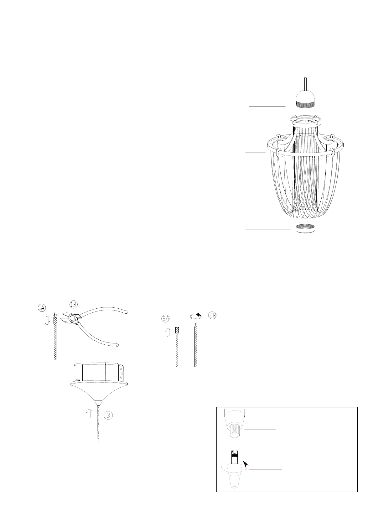
1.Position Socket Set LED303 so that threads through the hole
in the shade and screw on Ring from below by finger or Ring
Tool.
(See diagram).
For model MP-LED303:
Put the knitted cable from the Socket Set into
the cable grip (according to the steps 1,2,3, shown in the picture
below)
Twist the
cable with
pliers
For model QP-LED303:
1. Insert the post of the quick connect into the quick connect
adapter.
2. Thread the top half of the conical section until it is flush with
the adapter.
3. Adjust fixture position, but use caution not to loosen the
conical section.
Put the cable
into the MP-60E
Installing to Quick Connect
Quick connect adapter
quick connector
Socket Set
LED303
Shade
Protect
Glass
Page 2
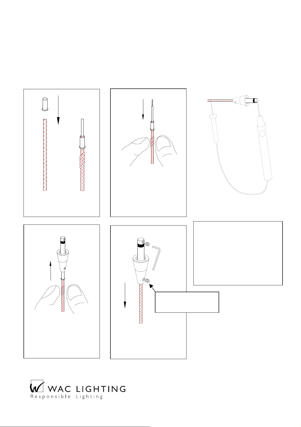
To Install / Shorten the cable:
Feed the cable end through the Top Conical section and the metal finial. If cable needs to be shortened, make
the cut now. To install the top conical section, follow the step-by-step instructions bellow. NOTE: Pendant
cables are co-axial, if the lower screw in step 4 is made too tight, the inner an outer wire will short. A
short circuit will render the entire system in-operative and possibly damage the transformer. Check all
pendant splices for continuity before installing.
Make a clean cut. Slide brass
collar over wire.
Trim 1/8” of insulation from
the inner wire. Position the
collar so that a small section
(1/16”) of braided wire
protrudes from the top of the
collar.
Feed inner wire until it
reaches the top set screw
position. Feed braided outer
wire and collar into bottom
portion.
Tighten top setscrew first then
lower. Smooth out any bulges
in braided wire. Perform
continuity check before
mounting.
1
2 3 4
Check Splice:
Before mounting, with lamp
removed from the socket, check for
continuity. There should be none.
Insert lamp in socket and re-check.
There should now be continuity,
indicating a completed circuit.
Install with power off.
Continuity tester
Retain these instructions for future service and adjustments
44 Harbor Park Drive, Port Washington, NY 11050
Tel: (800) 526-2588 Fax (800) 526-2585
www.waclighting.com
CAUTION:
Snug but not tight
 Loading...