

Page 1
INSTALLATION INSTRUCTION
Current Limiter - Surface Mount W Track
WEDL, WHEDL, WEDR, WHEDR
SAFETY INSTRUCTIONS:
• Please read through the entire Instruction prior to installation.
• Installation must conform to this instruction, and in accordance with National Electrical Code, and local code authority.
• Turn o power at main switch before installing any rack, or track device.
• Limit circuit load using appropriate W Track breaker.
• Device is not intended to be used as a conduit
OVERVIEW:
For connecting W Track Line Connector WEDL/WHEDL/WEDR/WHEDR to a 4” junction box, or conduit from a solid or
grid runner ceiling.
ELECTRICAL CONNECTIONS:
• Connector is polarized. Note the polarity indicator of the track and accessories.
• Connector Rating =20Amps per circuit. 120/277v, Single phase 60Hz.
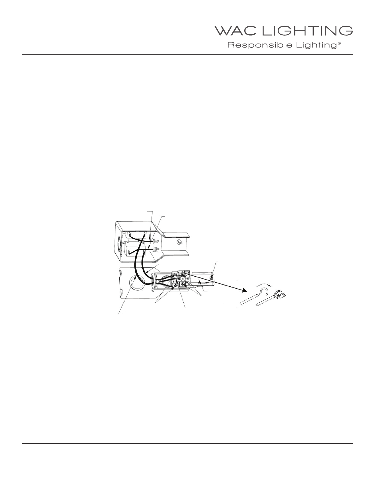
• All wiring to terminals of circuit breaker and two wiring to live terminals of track feeds are factory installed.Attach hot wire by
nut (supplied). Attach ground wire and white neutral wire tightly to the corresponding screw terminals. The single conductor
is bent around the screw in a 3/4 loop, insert the wires to the corresponding terminals (see g. below) and secure tightly with
a screw.
Circuit 1 Hot wire
Circuit 1 Hot
Jumper Wire
Circuit 2 Hot Jumper Wire
Live Terminal
Circuit 2 Hot wire
Locking Screw
Track Head
Neutral
Terminal
Ground
Terminal
WAC Lighting
www.waclighting.com
Phone (800) 526.2588 • Fax (800) 526.2585
WAC Lighting retains the right to modify the design of our products at any time as part of the company's continuous improvement program. SEPTEMBER, 2014
Headquarters/Eastern Distribution Center
44 Harbor Park Drive • Port Washington, NY 11050
Phone (516) 515.5000 • Fax (516) 515.5050
Western Distribution Center
1750 Archibald Ave • Ontario, CA 91761
Phone (800) 526.2588 • Fax (800) 526.2585
Page 2
INSTALLATION INSTRUCTION
Current Limiter - Surface Mount W Track
WEDL, WHEDL, WEDR, WHEDR
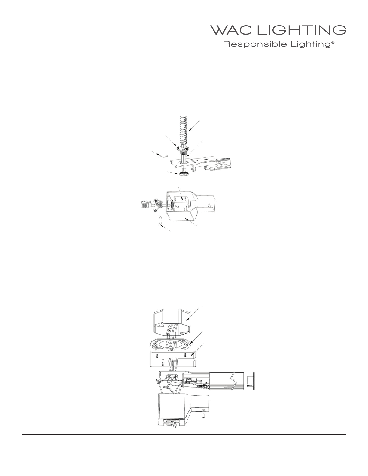
A: INSTALLING POWER LIMITER TO CONDUIT OR GRID RUNNER CEILING :
1. Remove Cover.
2. Remove appropriate knockout in Top Plate or Plastic Crust, and feed 3/8”or 1/2” Conduit and Supply leads into Top Plate or
Plastic Crust. Fasten Conduit to top plate or Plastic Crust.
3. Attach wires per electrical connection instructions.
4. Attach Track to Current Limiter. Be sure to check for proper polarity between track and switch. Also ensure all 5 contact plates
are properly inserted into each individual track circuit.
5. Replace Cover.
6. Secure the track to the ceiling.
Conduit Connector
(3/8” or 3/4”)
Knock Out
Locking Nut
Circuit Breaker
Conduit
Electrical Wire (5-12AWG)
Plastic Crust
Knock Out
B: INSTALLING CURRENT LIMITER TO 4” SPACE OCTAGONAL JBOX
Note: Center of track must coincide with center of J-Box
1. Remove appropriate knockout in Top Plate , and feed 3/8” or 1/2” Conduit and Supply leads into Top Plate. Fasten Conduit
to top plate.
2. Feed Supply wires through knockout hole. Attach wires per electrical connection instructions.
3. Attach Track to Current Limiter. Be sure to check for proper polarity between track and switch. Also ensure all 5 contact plates
are properly inserted into each individual track circuit.
4. Replace Cover.
5. Secure the track to the ceiling.
J-Box
Connection
Canopy
WAC Lighting
www.waclighting.com
Phone (800) 526.2588 • Fax (800) 526.2585
WAC Lighting retains the right to modify the design of our products at any time as part of the company's continuous improvement program. SEPTEMBER, 2014
Headquarters/Eastern Distribution Center
44 Harbor Park Drive • Port Washington, NY 11050
Phone (516) 515.5000 • Fax (516) 515.5050
Western Distribution Center
1750 Archibald Ave • Ontario, CA 91761
Phone (800) 526.2588 • Fax (800) 526.2585
 Loading...