

Page 1
INSTALLATION INSTRUCTION
LEDme®- 4” Invisible Trim™ IC Square
Remodel Housing - HR-LED418-RIC-SQ
SAFETY INSTRUCTION
IMPORTANT: NEVER attempt any work without shutting o the electricity.
• Read all instructions before installing.
• For installation by a qualied electrician.
• System is intended for installation in accordance with National Electric Code, and local regulations.
• Consult with local inspector to assure compliance.
• To reduce the risk of re, electrical shock and injuries to persons, turn o power at main switch before installing
or modifying the system.
• Warning: (Risk of re) do not install insulation within 3 inches of xture sides, or junction box, or in a manner to entrap heat.
• Retain instructions for future maintenance reference.
OVERVIEW:
Housing is remodeling type, 11 watts maximum. Housing requires an Invisible Trim™ from the HR-LED400TL series.
May be used with a standard incandescent dimmer switch, or an electronic low voltage (ELV) dimmer.
MOUNTING:
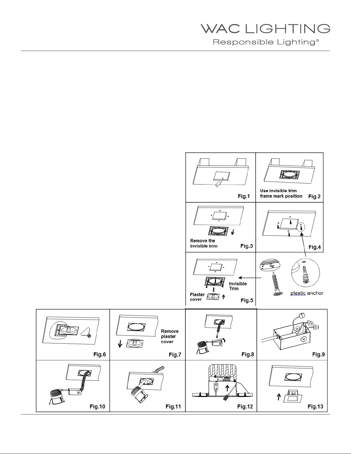
1. Cut out a hole 5” in the drywall (as Fig.1).
2. Raise Invisible Trim™ frame to ceiling opening as
a template to mark position of countersinks for plastic
anchors installation (as Fig.2 and Fig.3).
Install plastic anchors to ceiling (as Fig.4).
3. Raise Invisible Trim™ frame to ceiling opening and
secure with screws supplied (as Fig.5).
4. Apply plaster or spackle over Invisible Trim and sand surface
when dry for a nished look (as Fig.6). Remove plaster cover
(as Fig.7). Pull ceiling wire through the hole (as Fig.8).
5. Remove junction box door and connect xture wires to
building wires, insert each supply wire into appropriate
junction box connector. Connect black xture wire to hot,
white xture wire to neutral and green xture wire to
ground (as Fig.9).
6. Place all wiring and connectors back in wiring box and
replace junction box door (as Fig.10).
7. Pivot the J box up through the hole, followed by the
can (as Fig.11).
8. Raise the housing in the Invisible Trim and push the springs
outward from inside the can (as Fig.12).
9. Push the Invisible Trim assembly up until the Invisible Trim
is ush to the ceiling (as Fig.13).
WAC Lighting
www.waclighting.com
Phone (800) 526.2588 • Fax (800) 526.2585
WAC Lighting retains the right to modify the design of our products at any time as part of the company's continuous improvement program. JUNE, 2014
Headquarters/Eastern Distribution Center
44 Harbor Park Drive • Port Washington, NY 11050
Phone (516) 515.5000 • Fax (516) 515.5050
Western Distribution Center
1750 Archibald Ave • Ontario, CA 91761
Phone (800) 526.2588 • Fax (800) 526.2585
Page 2
INSTALLATION INSTRUCTION
LEDme®- 4” Invisible Trim™ IC Square
Remodel Housing - HR-LED418-RIC-SQ
REPLACE LED LENS:
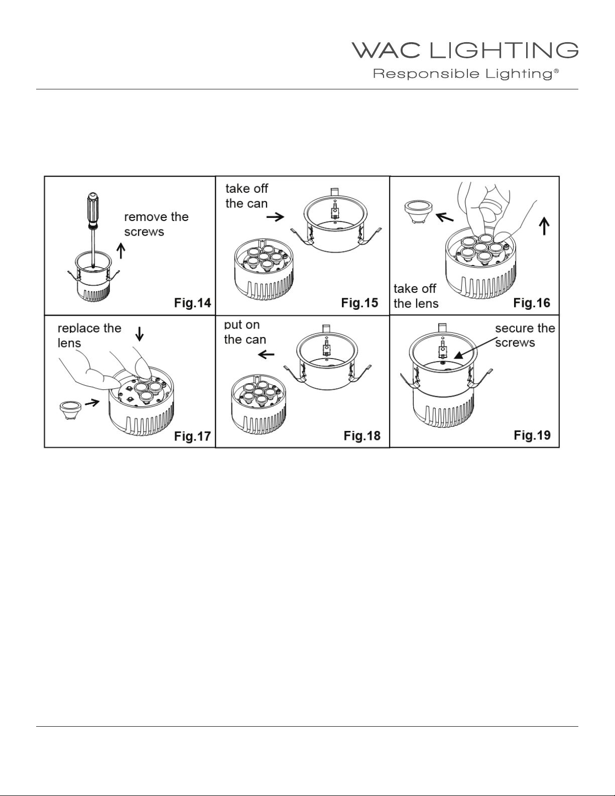
1. Remove the screws and take o the can (as Fig.14 and Fig.15).
2. Replace the lens you choose (as Fig.16 and Fig.17).
3. Put on the can and secure the screws (as Fig.18 and Fig.19).
WAC Lighting
www.waclighting.com
Phone (800) 526.2588 • Fax (800) 526.2585
WAC Lighting retains the right to modify the design of our products at any time as part of the company's continuous improvement program. JUNE, 2014
Headquarters/Eastern Distribution Center
44 Harbor Park Drive • Port Washington, NY 11050
Phone (516) 515.5000 • Fax (516) 515.5050
Western Distribution Center
1750 Archibald Ave • Ontario, CA 91761
Phone (800) 526.2588 • Fax (800) 526.2585
Page 3
INSTALLATION INSTRUCTION
LEDme®- 4” Invisible Trim™ Non-IC Square
Remodel Housing - HR-LED418-R-SQ
SAFETY INSTRUCTION
IMPORTANT: NEVER attempt any work without shutting o the electricity.
• Read all instructions before installing.
• For installation by a qualied electrician.
• System is intended for installation in accordance with National Electric Code, and local regulations.
• Consult with local inspector to assure compliance.
• To reduce the risk of re, electrical shock and injuries to persons, turn o power at main switch before installing
or modifying the system.
• Warning: (Risk of re) do not install insulation within 3 inches of xture sides, or junction box, or in a manner to entrap heat.
• Retain instructions for future maintenance reference.
OVERVIEW:
Housing is remodeling type, 18 watts maximum. Housing requires an Invisible Trim™ from the HR-LED400TL series.
May be used with a standard incandescent dimmer switch, or an electronic low voltage (ELV) dimmer
MOUNTING:
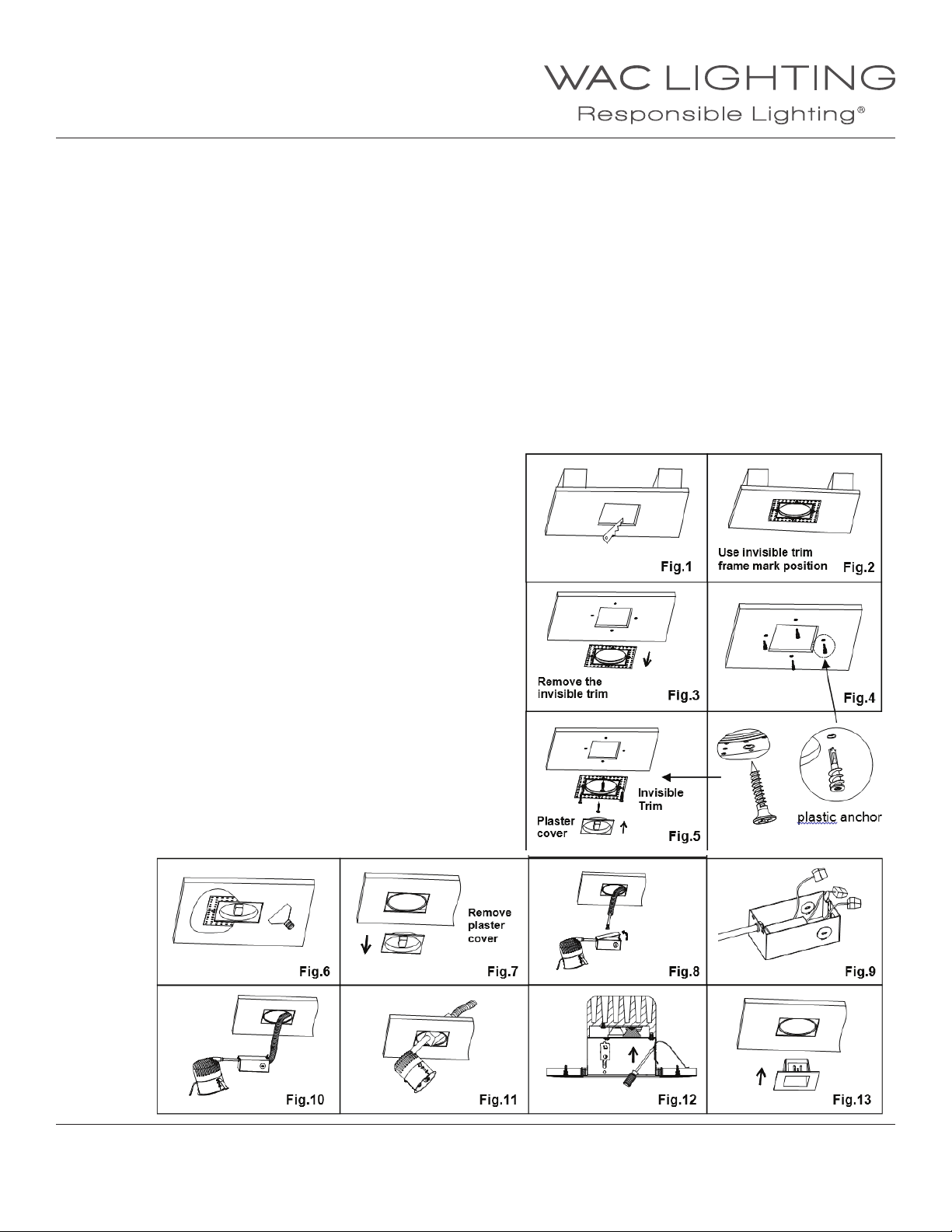
1. Cut out a hole 5” in the drywall (as Fig.1).
2. Raise Invisible Trim™ frame to ceiling opening as a template to
mark position of countersinks for plastic anchors installation
(as Fig.2 and Fig.3).
3. Install plastic anchors to ceiling (as Fig.4).
4. Raise Invisible Trim™ frame to ceiling opening and
secure with screws supplied (as Fig.5).
5. Apply plaster or spackle over Invisible Trim and sand surface
when dry for a nished look (as Fig.6).
6. Remove plaster cover (as Fig.7). Pull ceiling wire through
the hole (as Fig.8).
7. Remove junction box door and connect xture wires to building
wires, insert each supply wire into appropriate junction box
connector. Connect black xture wire to hot, white xture wire
to neutral and green xture wire to ground (as Fig.9).
8. Place all wiring and connectors back in wiring box and
replace junction box door (as Fig.10).
9. Pivot the J box up through the hole, followed by the can (as Fig.11).
10. Raise the housing in the Invisible Trim and push the springs
outward from inside the can (as Fig.12).
11. Push the Invisible Trim assembly up until the Invisible Trim
is ush to the ceiling (as Fig.13).
WAC Lighting
www.waclighting.com
Phone (800) 526.2588 • Fax (800) 526.2585
WAC Lighting retains the right to modify the design of our products at any time as part of the company's continuous improvement program. JUNE, 2014
Headquarters/Eastern Distribution Center
44 Harbor Park Drive • Port Washington, NY 11050
Phone (516) 515.5000 • Fax (516) 515.5050
Western Distribution Center
1750 Archibald Ave • Ontario, CA 91761
Phone (800) 526.2588 • Fax (800) 526.2585
Page 4
INSTALLATION INSTRUCTION
LEDme®- 4” Invisible Trim™ Non-IC Square
Remodel Housing - HR-LED418-R-SQ
REPLACE LED LENS:
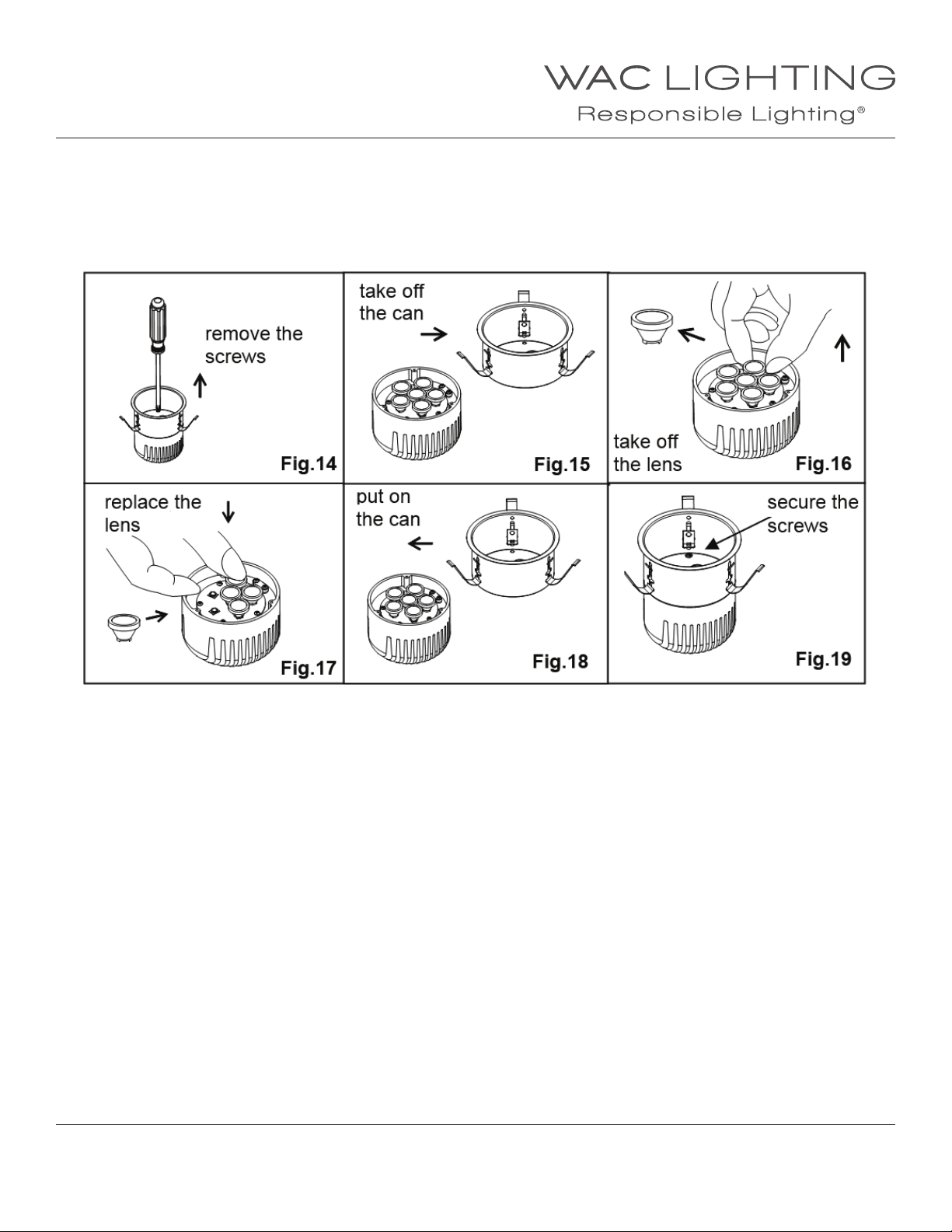
1. Remove the screws and take o the can (as Fig.14 and as Fig.15).
2. Replace the lens you choose (as Fig.16 and Fig.17).
3. Put on the can and secure the screws (as Fig.18 and Fig.19).
WAC Lighting
www.waclighting.com
Phone (800) 526.2588 • Fax (800) 526.2585
WAC Lighting retains the right to modify the design of our products at any time as part of the company's continuous improvement program. JUNE, 2014
Headquarters/Eastern Distribution Center
44 Harbor Park Drive • Port Washington, NY 11050
Phone (516) 515.5000 • Fax (516) 515.5050
Western Distribution Center
1750 Archibald Ave • Ontario, CA 91761
Phone (800) 526.2588 • Fax (800) 526.2585
 Loading...