

Page 1
INSTALLATION INSTRUCTION
Solorail™ System - Low Voltage
LM-T4, LM-T8
CAUTION:
• Read all instructions.
• Turn o power at main switch before installing or modifying the system.
• Do not conceal or extend exposed conductors through a building wall.
• Do not install any part of this system less that 7 feet ( 2.2m ) above the oor.
• Do not install the system:
- Within six inches of any curtain or combustible materials
- In a damp or wet location
• After rst 1/2 hour of operation, switch o and check all connections for excessive heat.
• Loose connections must be tightened to prevent overheating which can damage the system and pose a potential re hazard.
Do not over tighten.
• Intended for installation by a qualied electrician.
• Installation should be in accordance with NEC and local codes. Use minimum AWG #10 wire for secondary wiring.
OVERVIEW:
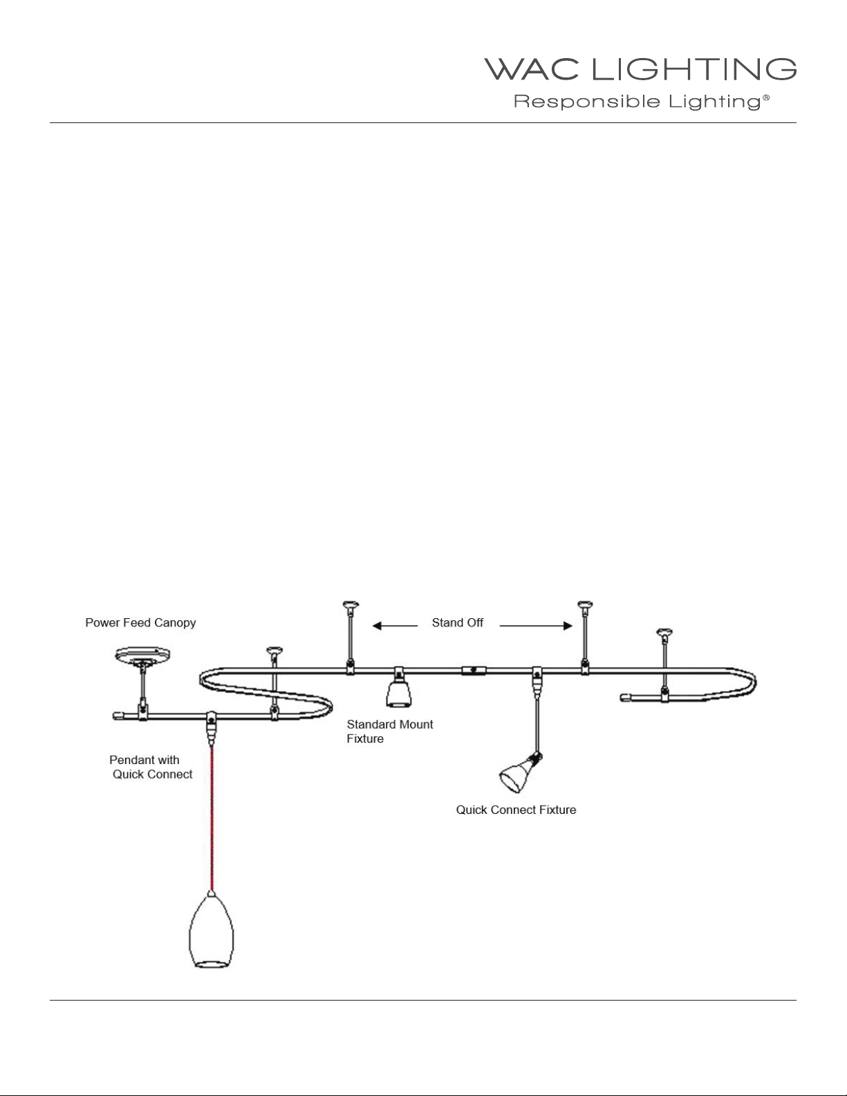
Flexible low volt Solorail™ is a single circuit rail that can be operated from either 12 or 24-volt power supplies, magnetic
or electronic, remote or surface mounted.
Solorail™ xtures include rail mounted heads, quick connect heads, and quick connect cable hung pendants.
Solorail™ mounts to ceilings by use of metal rod stand os, or cable and may be used on sloped or suspended ceilings.
DESIGN CONSIDERATIONS:
Solorail™ is composed of two copper conductors separated by a plastic insulator. It is exible and bendable. Rail is supplied in
4 or 8 ft lengths and may be eld cut. Stand o’s are available in 3 to 6 inch lengths, and longer lengths for high ceiling
applications. Solorail™ maximum loads are 300 watts at 12 volts and 600 watts at 24 volts. Rail is 25 amp rated. Voltage drop is an
important consideration in the initial design. The length of a monorail run depends on the distance from the transformer and the
wattage load. Wire gauge size is also a factor in how far a remote transformer may be located from the rail.
Consult the voltage drop guideline chart.
WAC Lighting
www.waclighting.com
Phone (800) 526.2588 • Fax (800) 526.2585
WAC Lighting retains the right to modify the design of our products at any time as part of the company's continuous improvement program. JUNE, 2014
Headquarters/Eastern Distribution Center
44 Harbor Park Drive • Port Washington, NY 11050
Phone (516) 515.5000 • Fax (516) 515.5050
Western Distribution Center
1750 Archibald Ave • Ontario, CA 91761
Phone (800) 526.2588 • Fax (800) 526.2585
Page 2
INSTALLATION INSTRUCTION
Solorail™ System - Low Voltage
LM-T4, LM-T8
TRANSFORMER SELECTION GUIDE:
Either electronic or magnetic transformers can power monorail. Electronics are smaller than magnetic. The larger magnetic
transformers have greater wattage capacities. There is a lesser degree of voltage drop in a magnetic transformer, making them
a more practical choice for longer runs (see voltage drop guidelines). Electronic transformers oer quieter operation than
magnetics, making them a more practical choice for quiet settings. Magnetic transformers generally contain less components
making them among the most reliable power sources.
Either transformer can be used with dimmer switches. An electronic low volt dimmer switch is recommended with any electronic
transformer. Electronic transformers are not suitable for multiple switch locations (one switch per transformer).
A magnetic transformer requires a low voltage dimmer specically made for magnetic loads. All dimmers always install
on the primary side of the transformer.
Because the Solorail™ system works with 12 or 24 volts we oer transformers for either voltage. The maximum amperage of the
rail is 25 amps. You may run 600 watts on a 24 volt system (25 amps) or 300 watts on a 12 volt system ( also 25 amps).
Our 600 watt transformers are oered in 12 or 24 volts, however the 12 volt version has two outputs with 300 watts available
at each.
Transformers are available as surface mounts or remote. Surface mount transformers mount to a junction box,
due to their weight it is important that the box be adequately secured to the ceiling structure.
Most of our remote magnetic transformers have a boost tap option, which allows the transformer to be wired for a slightly higher
(approximately 10%)voltage output to compensate for voltage drop. To use see instructions furnished with the transformer.
TRANSFORMER SELECTION GUIDELINE
MODEL TYPE INPUT OUTPUT MAX WATTS
LM-EN12-75E Surface Mount LED 120V 12V 75W
LM-EN12-150M Surface mount magnetic 120V 12V 150W
LM-EN12-300M Surface mount magnetic 120V 12V 300W
LM-EN12-600M Surface mount magnetic 120V 12V 600W dual output
LM-EN12-150E Surface mount electronic 120V 12V 150W
LM-EN12-250E Surface mount electronic 120V 12V 250W
SRT-300M-12V Remote magnetic 120V 12V 300W
SRT-300M-24V Remote magnetic 120V 24V 300W
SRT-600M-12V Remote magnetic 120V 12V 600W dual output
SRT-600M-24V Remote magnetic 120V 24V 600W dual output
WAC Lighting
www.waclighting.com
Phone (800) 526.2588 • Fax (800) 526.2585
WAC Lighting retains the right to modify the design of our products at any time as part of the company's continuous improvement program. JUNE, 2014
Headquarters/Eastern Distribution Center
44 Harbor Park Drive • Port Washington, NY 11050
Phone (516) 515.5000 • Fax (516) 515.5050
Western Distribution Center
1750 Archibald Ave • Ontario, CA 91761
Phone (800) 526.2588 • Fax (800) 526.2585
Page 3
INSTALLATION INSTRUCTION
Solorail™ System - Low Voltage
LM-T4, LM-T8
VOLTAGE DROP GUIDELINE
SURFACE MOUNT TRANSFORMERS
CAT. NO. VOLTS WATTS TYPE RAIL RUN LENGTH
LM-EN12-75E 12V 75W ELECTRONIC (9) 9W LED xtures
LM-EN12-150M 12V 150W MAGNETIC 40’
LM-EN12-150E 12V 150W ELECTRONIC 20’
LM-EN12-250E 12V 250W ELECTRONIC 16’
LM-EN12-300M 12V 300W MAGNETIC 40’
LM-EN12-600M 12V (2) 300W MAGNETIC (2) 40’
REMOTE TRANSFORMERS to power feed point
CAT.NO. VOLTS WATTS TYPE
SRT-300M-12V* 12V 300W MAGNETIC 9’ 10’ 25’ 40’ 60’ 100’ 40’
SRT-300M-24V* 24V 300W MAGNETIC 15’ 20’ 40’ 60’ 100’ 150’ 80’
WIRE GAUGES/ MAX DISTANCE-FEET RAIL RUN LENGTH/FT
10 8 6 4 2 1
SRT-600M-12/24V* 12/V (2) 300W MAGNETIC 9’ 10’ 25’ 40’ 60’ 100’ (2) 40’
SRT-600M-12/24V* 24V (1) 600W MAGNETIC 9’ 10’ 25’ 40’ 60’ 100’ 40’
* Transformers with booth tap option increases voltage approximately 10%.
Remote transformer data based on a full load with 5% max voltage drop.
Surface mount data based on full load to end of rail.
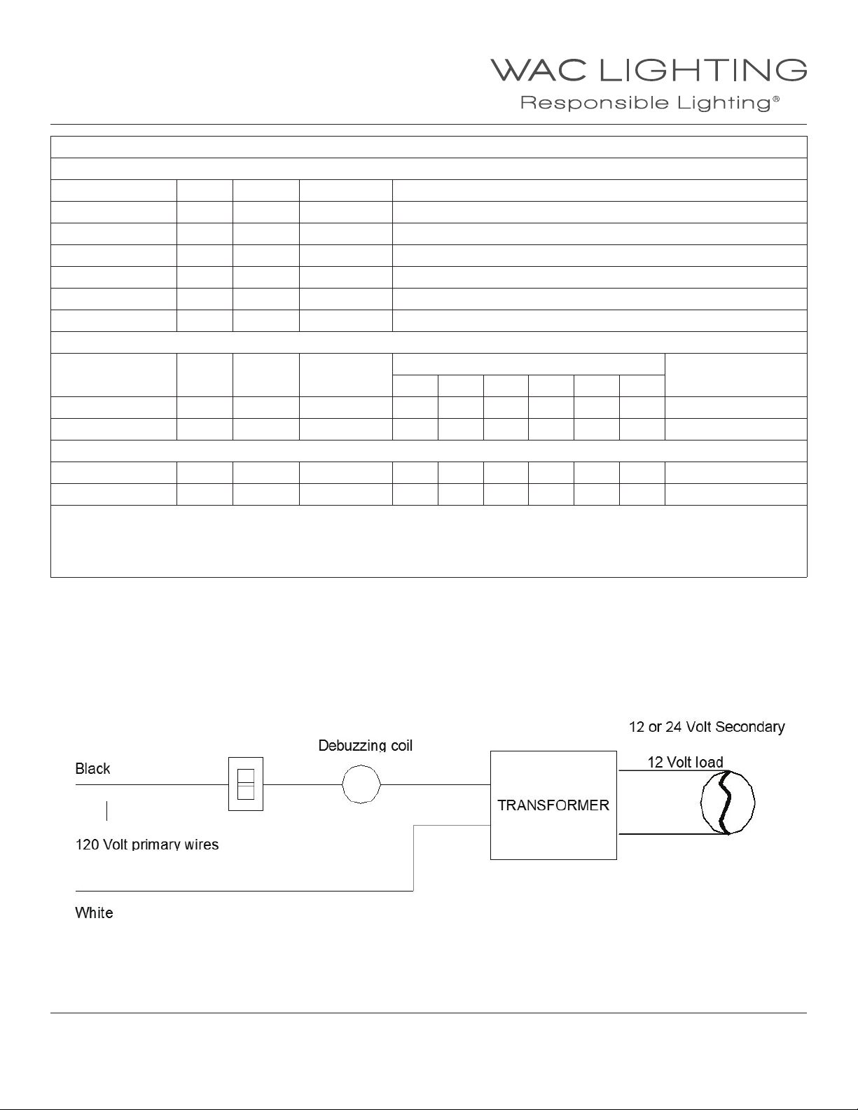
DEBUZZING COIL:
Inherint with all magnetic transformers is an audible buzz, mostly when dimmed. To lessen the noise, our surface mount
transformers are supplied with a factory installed debuzzing coil (or choke). The debuzzing coil is an option on
remote magnetic transformers. Debuzzing coils are installed between the switch and transformer on the black (hot) primary wire.
WAC Lighting
www.waclighting.com
Phone (800) 526.2588 • Fax (800) 526.2585
WAC Lighting retains the right to modify the design of our products at any time as part of the company's continuous improvement program. JUNE, 2014
Headquarters/Eastern Distribution Center
44 Harbor Park Drive • Port Washington, NY 11050
Phone (516) 515.5000 • Fax (516) 515.5050
Western Distribution Center
1750 Archibald Ave • Ontario, CA 91761
Phone (800) 526.2588 • Fax (800) 526.2585
Page 4
INSTALLATION INSTRUCTION
Solorail™ System - Low Voltage
LM-T4, LM-T8
TRANSFORMER INSTALLATION:
Determine if a remote or surface mount transformer will be used,
proceed as indicated below.
INSTALLING A REMOTE TRANSFORMER:
1. Locate the transformer as close as possible to the power feed
point to minimize voltage drop.
2. Connect line voltage wires to their respective transformer
input wires, ( white to white & black to black).
3. Make ground wire connection. Note: Some remote
transformers have integral enclosures with a green wire, if not,
an enclosure is required. Establish a ground connection to the
enclosure.
4. To wire secondary wires, rst determine the appropriate THHN
wire gauge size for the distance between the transformer
and the junction box. See voltage drop chart . Run secondary
wires from transformer to power in walls and ceilings should
be enclosed type ie: BX, Romex, MC.
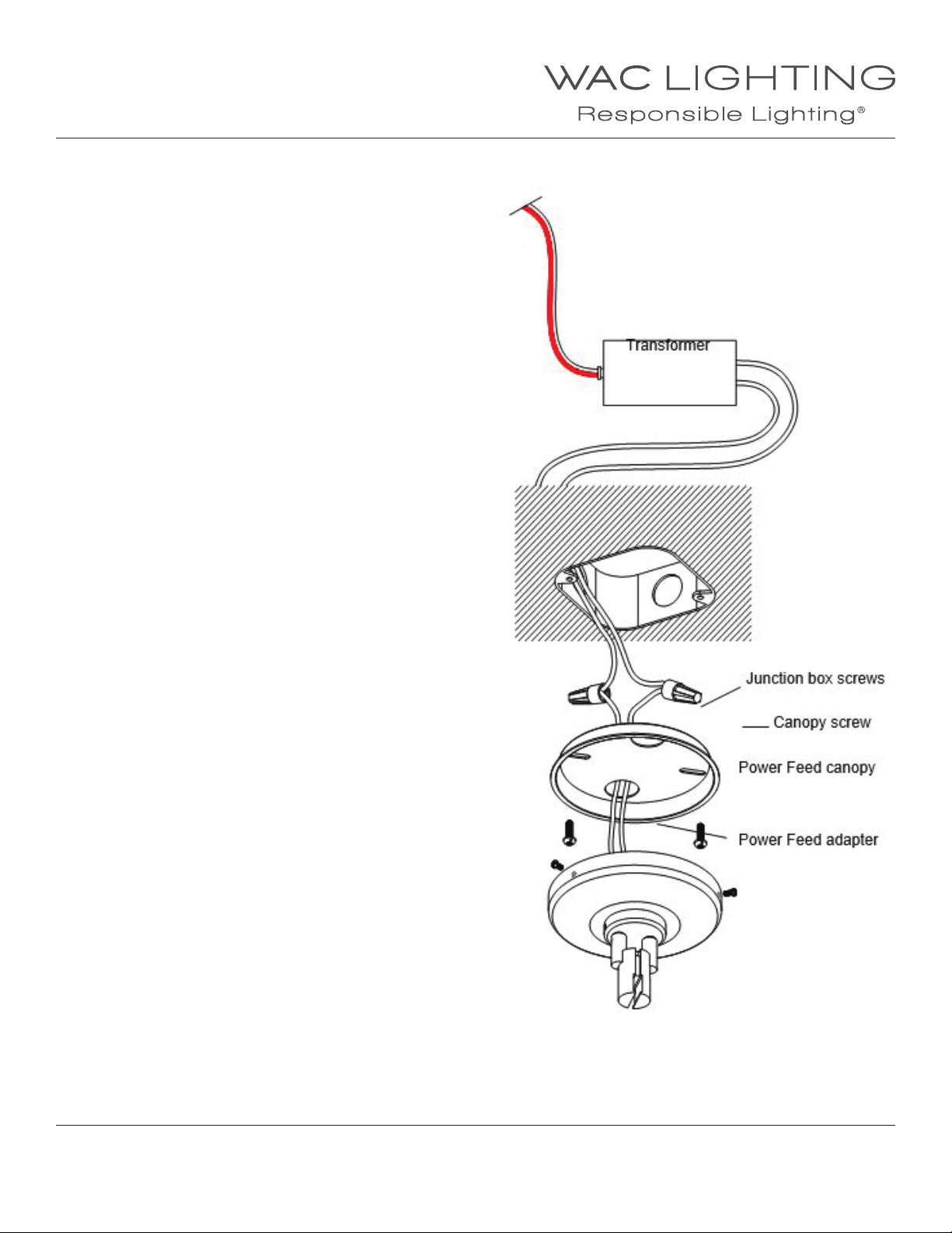
5. Select a knock out hole in the power feed canopy back plate.
6. Support the power feed canopy, and route wires from the
canopy through the the knock out hole into the junction box.
120V input wires
Out put wires: See voltage drop
table to select correct THHN wire
gauge size. Use conduit or Romex
where required by code.
7. Attach canopy wires to the transformer wires with wire nuts
(supplied). Tuck wires back into the junction box.
8. Secure the base plate to the junction box, through the slotted
holes.
9. Loosen the the three screws on the canopy. Raise the power
feed canopy to the base plate and partially tighten screws so
that they support the weight of the canopy.
10. Rotate the canopy so the power feed adapter aligns with the
rail, then fully tighten screws.
11. For locations where no junction box is present secure the
back plate to the surface, and make wire connections in the
canopy.
12. NOTE: Low voltage systems require rm connections at all
points, to avoid abnormal heat conditions. A loose connection
can lead to system damage and potential re hazzard. Correct
by tightening, but do not over tighten. The recheck the hot
spot to make certain it’s corrected.
WAC Lighting
www.waclighting.com
Phone (800) 526.2588 • Fax (800) 526.2585
WAC Lighting retains the right to modify the design of our products at any time as part of the company's continuous improvement program. JUNE, 2014
Headquarters/Eastern Distribution Center
44 Harbor Park Drive • Port Washington, NY 11050
Phone (516) 515.5000 • Fax (516) 515.5050
Western Distribution Center
1750 Archibald Ave • Ontario, CA 91761
Phone (800) 526.2588 • Fax (800) 526.2585
Page 5
INSTALLATION INSTRUCTION
Solorail™ System - Low Voltage
LM-T4, LM-T8
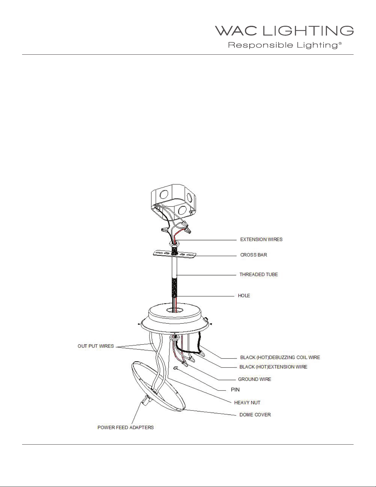
INSTALLING A SURFACE MOUNTED TRANSFORMER:
1. The junction box will support the entire weight of the transformer, which may weigh up to 18 lbs.;
make sure it is adequately braced and supported. It is recommended that two people install the transformer.
2. Extension wires are supplied to connect junction box wires to the transformer input wires.
Connect white neutral wire to white wire, and black hot wire to black wire with wire nuts.
The ground wire may be green or bare copper, connect it to the green extension wire.
3. Pass the open ends of the wires through the center hole of the cross bar/ threaded tube assembly,
and mount to cross bar junction box as shown.
4. Open the transformer case by removing the four screws on the perimeter. The cover halves will separate but not detach,
allow the lower half to hang temporarily.
5. Raise the transformer assembly on to the threaded tube and pass the ends of the wires through.
Attach the heavy nut to the bottom of the tube and tighten so the transformer assembly is close to the ceilling.
6. Insert pin through hole on bottom of treaded tube to secure heavy nut to tube.
7. Connect the extension wires to the transformer input wires, with wire nuts. Follow the previous color code.
8. Position the bottom cover so the power feed adapter is aligned to receive Solorail™.
Close the bottom cover and secure with the four secrews removed earlier.
WAC Lighting
www.waclighting.com
Phone (800) 526.2588 • Fax (800) 526.2585
WAC Lighting retains the right to modify the design of our products at any time as part of the company's continuous improvement program. JUNE, 2014
Headquarters/Eastern Distribution Center
44 Harbor Park Drive • Port Washington, NY 11050
Phone (516) 515.5000 • Fax (516) 515.5050
Western Distribution Center
1750 Archibald Ave • Ontario, CA 91761
Phone (800) 526.2588 • Fax (800) 526.2585
Page 6
INSTALLATION INSTRUCTION
Solorail™ System - Low Voltage
LM-T4, LM-T8
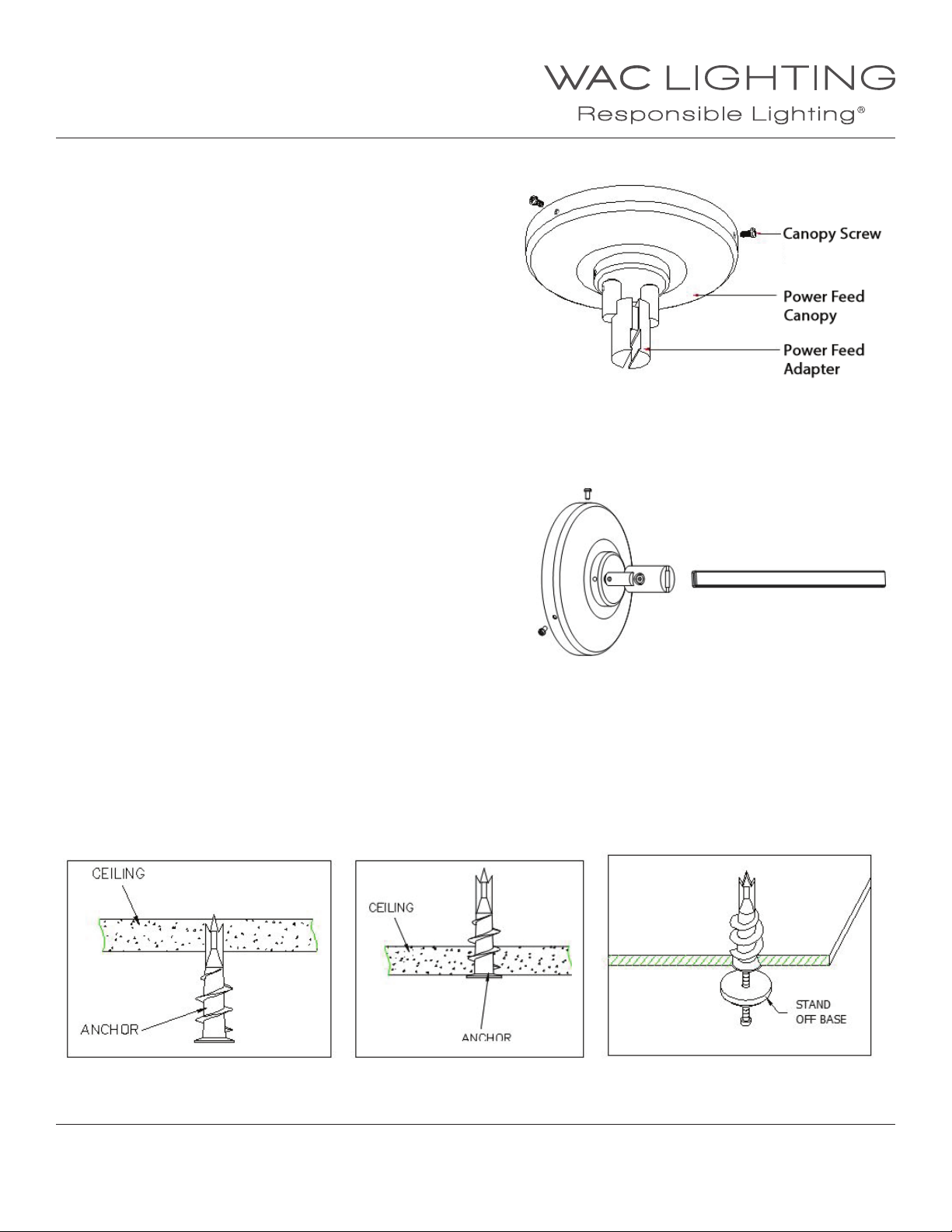
CEILING POWER FEED CONNECTION: “LMCPC”
1. Position the transformer or power feed canopy,
so the power feed adapters align with the rail.
2. Loosen the set screw in the adapter, so that there is sucient
clearence to slip the monorail between the two halves.
3. Gently seat the rail in position and tighten the adapter screw,
making sure the rubber separator stays in position.
4. Check the t of the rail, to make sure it ts at against the
adapter channel. Complete contact is necessary for propper
performance.
5. After the rst ½ hour of operation, switch o and check
connections for excessive heat or color distortion.
Low voltage systems operate at higher amperage,
which requires secure connections., A loose connection
can lead to system damage and potential re hazzard.
Correct by tightening, but do not over tighten.
The recheck the hot spot to make certain it’s corrected.
INSTALLING A REMOTE TRANSFORMER:
The wall mount power feed installation is the same as ceilling
mount. It diers from the ceiling mount in that the power feed
adapter is shaped to accept rail from it’s end.
MONORAIL MOUNTING:
Rail can be installed on a at surface, a sloped ceiling,
or a suspended ceiling.
1. Use a stando for every 42” of rail. Use additional standos
to support tightly curved sections .
2. If bending rail, do this at oor level, then raise to ceiling
and mark the location of stando supports.
3. If rail cannot be raised, use a plumb line to mark location
of stand os on the ceiling.
4. For drywall, drill holes and insert ceiling anchors (supplied)
through stando bases and then to ceiling (shown).
Tighten until snug.
WAC Lighting
www.waclighting.com
Phone (800) 526.2588 • Fax (800) 526.2585
WAC Lighting retains the right to modify the design of our products at any time as part of the company's continuous improvement program. JUNE, 2014
Headquarters/Eastern Distribution Center
44 Harbor Park Drive • Port Washington, NY 11050
Phone (516) 515.5000 • Fax (516) 515.5050
Western Distribution Center
1750 Archibald Ave • Ontario, CA 91761
Phone (800) 526.2588 • Fax (800) 526.2585
Page 7
INSTALLATION INSTRUCTION
Solorail™ System - Low Voltage
LM-T4, LM-T8
5. For wood surfaces insert wood screws through
stando basses and fully tighten.
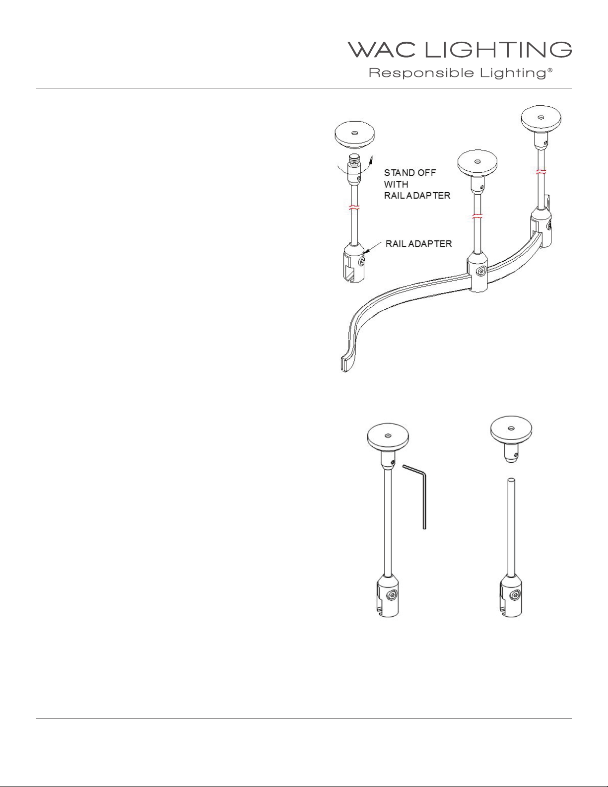
6. Install stando posts with rail adapters.
Twist clock wise to tighten.
7. To obtain proper alignment with Solorail™ loosen the
set screw near the top of the stando,
(using a 1/16” allen wrench) adjust then re- tighten.
8. Loosen the set screw in the rail adapter, so that there is
sucient clearence to slip the rail between the two halves.
9. Raise the rail to ceiling level and support it.
10. Starting from the center of rail, slip track between the
two halves of the rail adapter. Tighten the adapter screw
(clockwise) until the rail adapter seats rmly against both
sides of the rail.
11. Repeat procedure for remaining standos
FIELD CUTTING A STANDOFF:
1. Remove the small setscrew located on the upper tting and
pull the rod free (use a 1/16” allen wrench).
2. Use a tube cutter for the cleanest cut. If using a hacksaw be
sure to brush away any metal lings.
3. Cut to size and ret.
4. The procedure for standos on the power feed canopy is the
same
WAC Lighting
www.waclighting.com
Phone (800) 526.2588 • Fax (800) 526.2585
WAC Lighting retains the right to modify the design of our products at any time as part of the company's continuous improvement program. JUNE, 2014
Headquarters/Eastern Distribution Center
44 Harbor Park Drive • Port Washington, NY 11050
Phone (516) 515.5000 • Fax (516) 515.5050
Western Distribution Center
1750 Archibald Ave • Ontario, CA 91761
Phone (800) 526.2588 • Fax (800) 526.2585
Page 8
INSTALLATION INSTRUCTION
Solorail™ System - Component
LM-T4, LM-T8
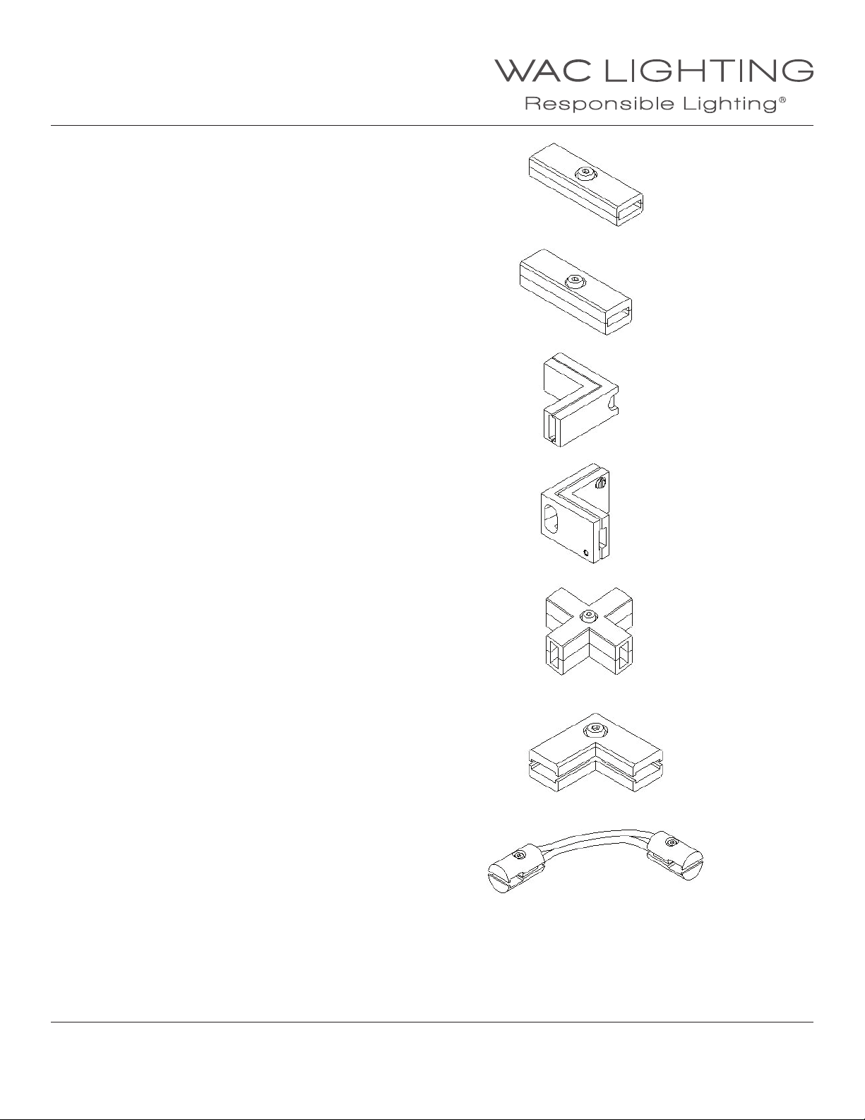
“I”CONNECTOR - LM-I
Connects two sections of rail and allows current ow
between the two.
“I”DEAD END CONNECTOR - LM-IDEC
Connects two pieces of rail, but is non-conductive
and does not allow current to pass to the other section.
“L”CONNECTOR - LM-L
Used to join two rail sections at a 90°angle.
“T”CONNECTOR - LM-T
Joins three rails in a “T” conguration.
“X”DEAD END CONNECTOR - LM-XDEC
Connects four sections of rail, but is non-conductive
and does not allow current to pass to the
other sections.
CEILING TO WALL “L”CONNECTOR - LM-CW
Joins rail sections on a vertical plane to allow
a transition from a wall to ceiling
JUMPER SET - LM-JS
Connects two monorail sections with a exible
wire allowing variable angles. Length is 8.5”.
WAC Lighting
www.waclighting.com
Phone (800) 526.2588 • Fax (800) 526.2585
WAC Lighting retains the right to modify the design of our products at any time as part of the company's continuous improvement program. JUNE, 2014
Headquarters/Eastern Distribution Center
44 Harbor Park Drive • Port Washington, NY 11050
Phone (516) 515.5000 • Fax (516) 515.5050
Western Distribution Center
1750 Archibald Ave • Ontario, CA 91761
Phone (800) 526.2588 • Fax (800) 526.2585
Page 9
INSTALLATION INSTRUCTION
Solorail™ System - Component
LM-T4, LM-T8
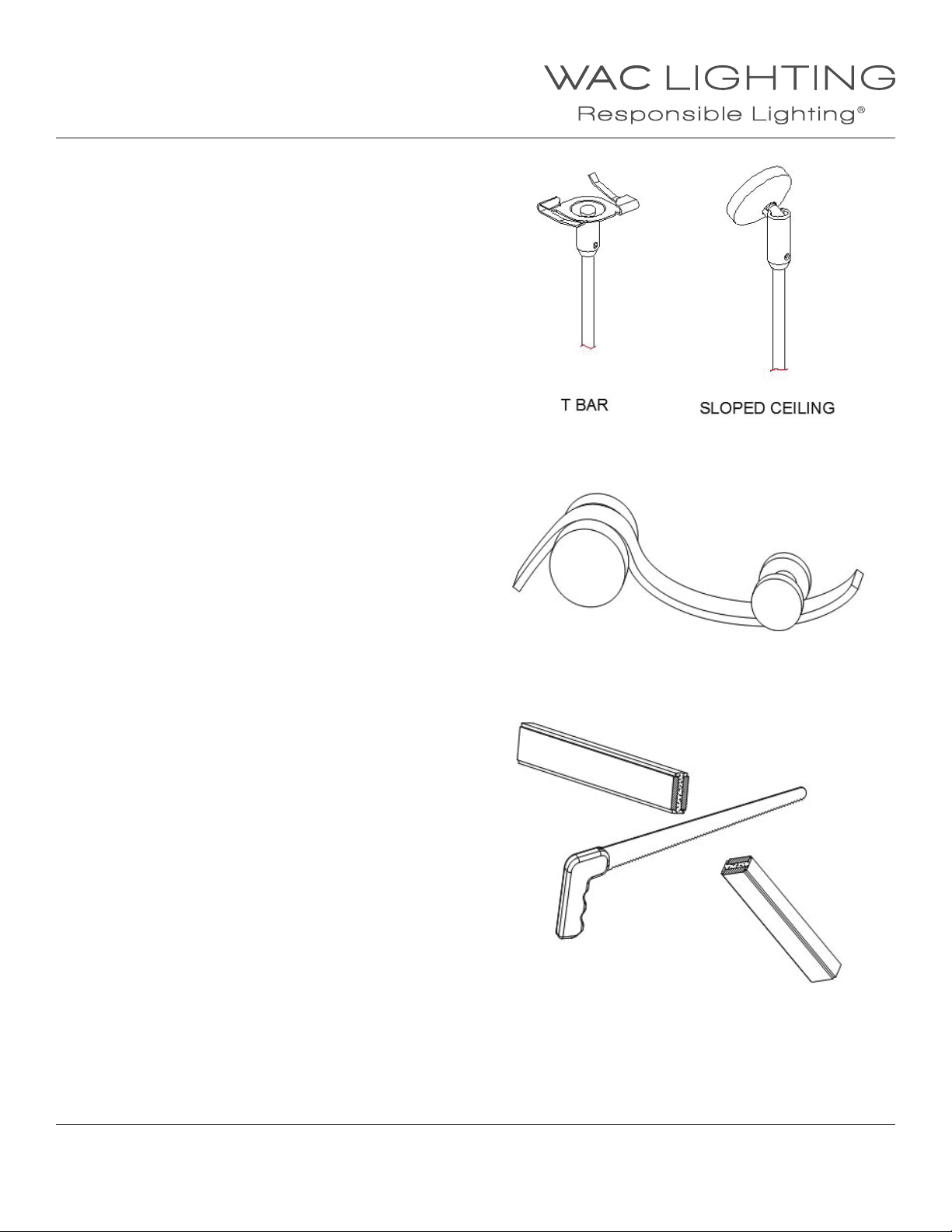
TBAR CEILINGS
NOTE: Rail stand os are required to be mounted to structural
members. Do not mount only to acoustical panels.
1. Follow steps 1 through 3 for rail mounting above.
2. Place T-bar clip stando against the ceiling T-bar,
and turn clockwise to engage.
3. Proceed from step 5 above.
BENDING SOLORAIL™
1. Rail is best formed, by bending over a round object.
2. Start with a broader radius and form over progressively
smaller diameters.
3. We recommend a minimum radius of 12”.
4. Broad curves can be accomplished by gradual hand bending.
5. Once formed, the ends of the rail will be unequal.
If connecting with another connector, snip the rail end
to make even, other wise just apply an end cap.
6. Pre-stress track to shape while at oor level.
Do not stress between ceiling standos to form shapes.
FIELD CUTTING RAIL
1. Rail may cut to length in eld.
2. Use ne-toothed hacksaw or heavy-duty bolt cutter.
3. Thoroughly clear away all cutting debris.
4. Inspect end to insure the insulator has not been
damaged and there are no sharp edges.
5. Re-install track end cap.
WAC Lighting
www.waclighting.com
Phone (800) 526.2588 • Fax (800) 526.2585
Headquarters/Eastern Distribution Center
44 Harbor Park Drive • Port Washington, NY 11050
Phone (516) 515.5000 • Fax (516) 515.5050
Western Distribution Center
1750 Archibald Ave • Ontario, CA 91761
Phone (800) 526.2588 • Fax (800) 526.2585
WAC Lighting retains the right to modify the design of our products at any time as part of the company's continuous improvement program. JUNE, 2014
Page 10
INSTALLATION INSTRUCTION
Solorail™ System - Component
LM-T4, LM-T8
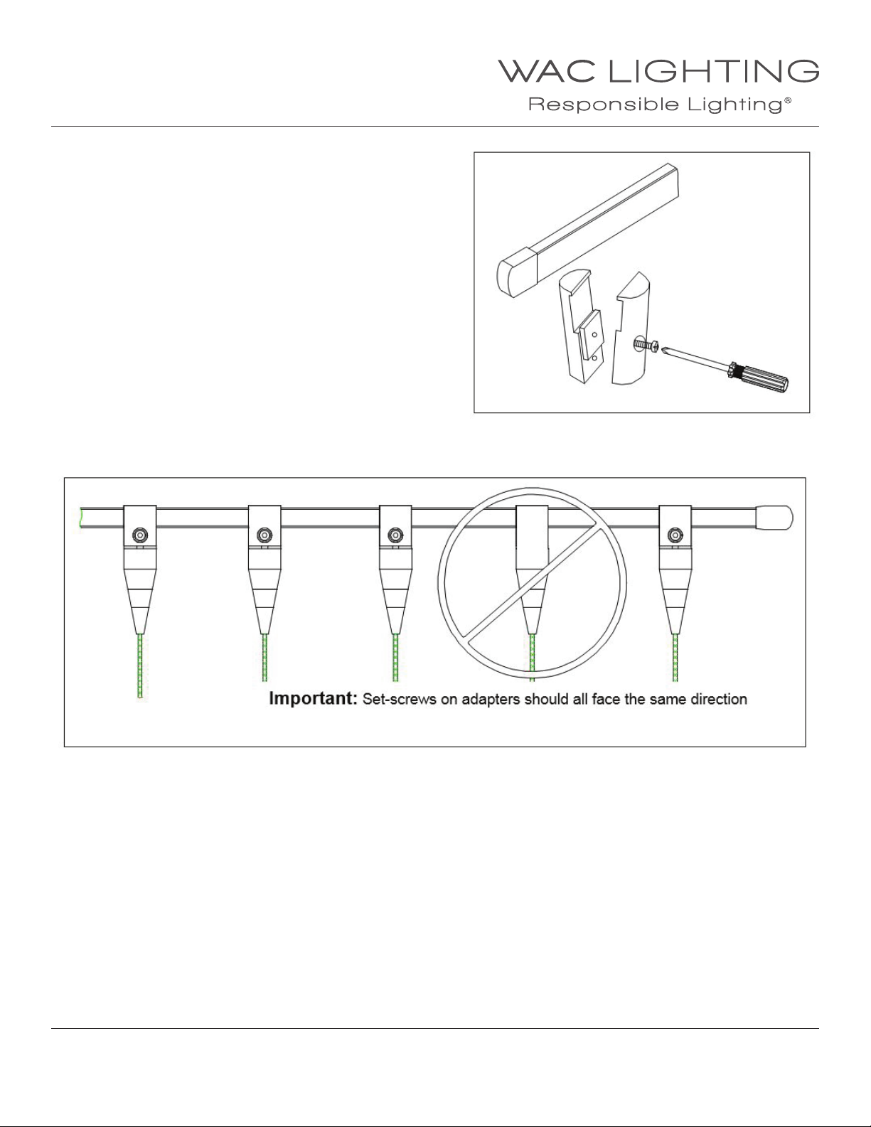
INSTALLING FIXTURES:
NOTE: Fixtures attach to the rail with a two-piece adapter.
It is important that the setscrews of the adapter all face the
same way. This reduces the possibility of an electrical short.
1. Loosen the adapter screw enough to allow adapter
halves to slip over Solorail™.
2. Seat the adapter notches to the rail and tighten the screw.
3. Inspect the rail to see that the adapters are rm against it.
4. If the adapter is the quick connect type, thread the
quick connect adapter by screwing clockwise until snug.
IMPORTANT: Observe polarity, install rail adapters with screws facing the same side of the rail.
WAC Lighting
www.waclighting.com
Phone (800) 526.2588 • Fax (800) 526.2585
WAC Lighting retains the right to modify the design of our products at any time as part of the company's continuous improvement program. JUNE, 2014
Headquarters/Eastern Distribution Center
44 Harbor Park Drive • Port Washington, NY 11050
Phone (516) 515.5000 • Fax (516) 515.5050
Western Distribution Center
1750 Archibald Ave • Ontario, CA 91761
Phone (800) 526.2588 • Fax (800) 526.2585
 Loading...