

Page 1
INSTALLATION INSTRUCTION
Flexrail1™ System - Line Voltage
HM1-T4, HM1-T8
SAFETY INSTRUCTION
Only a qualied electrician must install system. System is intended for installation in accordance
with National Electric Code, local and Federal code specications.
To reduce the risk of re, electrical shock and injuries to persons:
1. Read all instructions.
2. Turn o power at main switch before installing or modifying the system.
3. Do not install within six inches of any curtain or combustible materials.
4. Do not install less than 5 feet above a oor.
5. Do not install in damp or wet locations.
6. Do not install concealed, or extended through building walls.
7. Do not attempt to energize anything other than a track light xture.
8. Do not load rail to more than 20 amps per circuit.
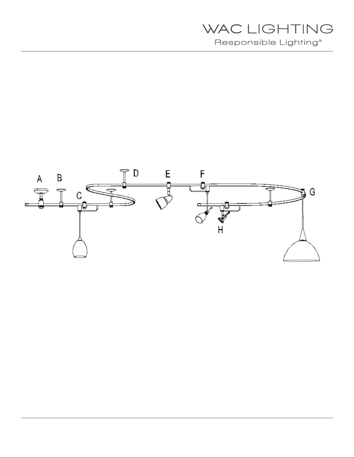
A = Power feed
B = Stando
C = Quick Connect transformer with low volt pendant
D = “I” Connector ( joins two rail sections & supports)
E = Line volt xture
F = Quick Connect transformer with low volt xture
G = Line Volt pendant
H = Low volt xture
OVERVIEW:
• Line volt bendable rail (24” min radius). May be hand bent, optional bending tool for large jobs.
• Mounting options for at, sloped or T-bar ceilings.
• Allows custom length ceiling suspension.
• Available in 4 & 8 ft lengths and may be joined to form longer runs.
• Use rope, chalk or string on oor level, or a scale drawing with string to estimate rail needs.
• Accepts Line volt and low volt xtures, line volt pendants, and quick connect transformers used with
QC series pendants or xtures.
• Powers from a standard ceiling junction box.
WAC Lighting
www.waclighting.com
Phone (800) 526.2588 • Fax (800) 526.2585
Headquarters/Eastern Distribution Center
44 Harbor Park Drive • Port Washington, NY 11050
Phone (516) 515.5000 • Fax (516) 515.5050
Western Distribution Center
1750 Archibald Ave • Ontario, CA 91761
Phone (800) 526.2588 • Fax (800) 526.2585
WAC Lighting retains the right to modify the design of our products at any time as part of the company's continuous improvement program. JUNE, 2014
Page 2
INSTALLATION INSTRUCTION
Flexrail1™ System - Line Voltage
HM1-T4, HM1-T8
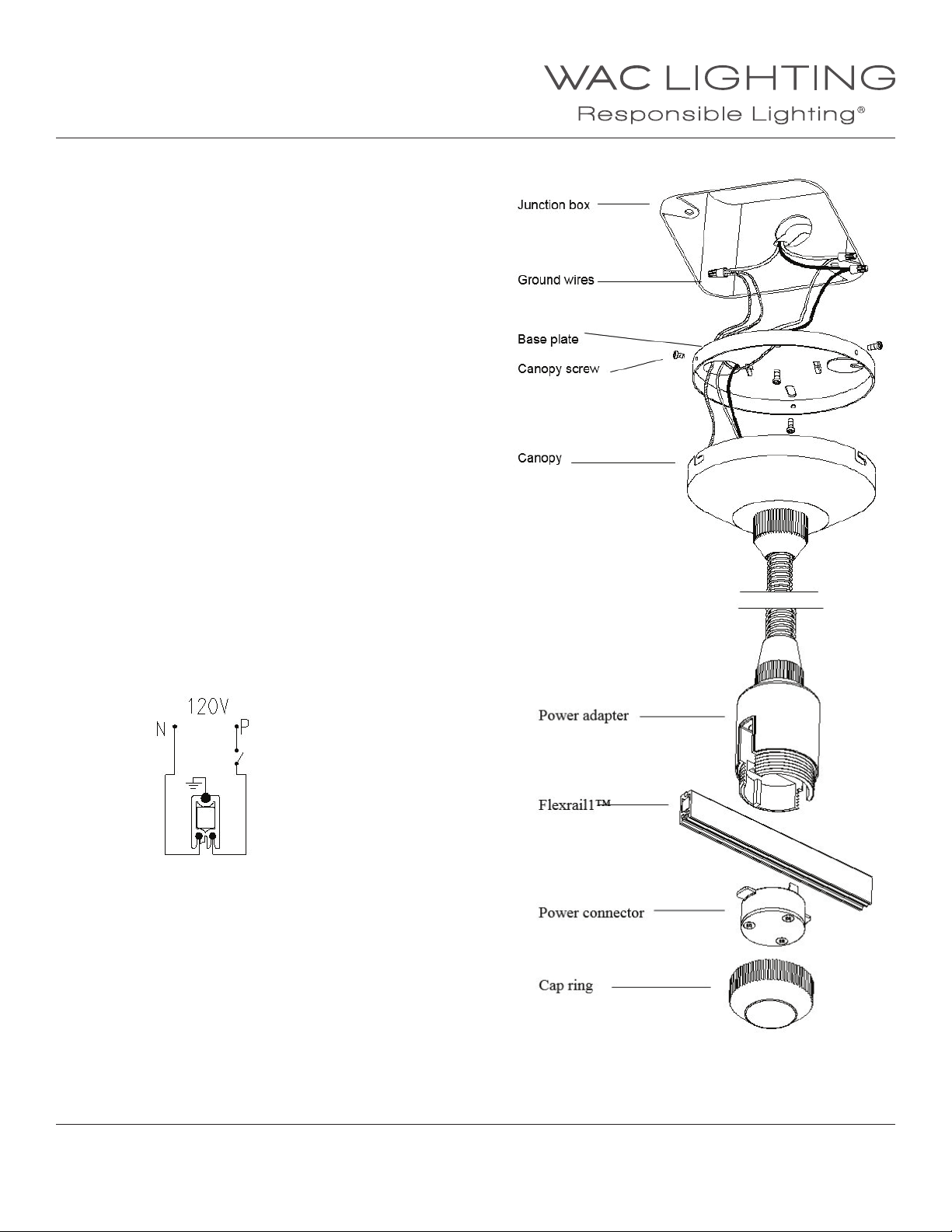
FEEDING POWER TO CANOPY:
1. Make sure the rail passes under, or close to
a junction box. Power may be introduced at any
point along the rail.
2. Loosen canopy screws and separate canopy plate
and base plate.
3. Remove a knock out and route wires into the
junction box.
4. Connect Black (hot) wire from building to black system
wire. Connect white-to-white wires.
5. The green wire is the ground wire to be connected
with the ceiling ground wire.
6. Secure all connections with wire nuts and tuck excess
wire back into the junction box.
7. Secure the base plate to the junction box, with two
screws through the slotted holes.
8. Install the canopy to the base plate.
POWER FEED TO RAIL:
1. Unscrew the cap ring (counterclockwise).
2. Remove the power connector by pulling straight down.
(bottom screws are factory installed do not remove).
3. Place rail into the power adapter, then re- install
the power connector.
4. Re-install the cap ring.
Wire diagram:
WAC Lighting
www.waclighting.com
Phone (800) 526.2588 • Fax (800) 526.2585
WAC Lighting retains the right to modify the design of our products at any time as part of the company's continuous improvement program. JUNE, 2014
Headquarters/Eastern Distribution Center
44 Harbor Park Drive • Port Washington, NY 11050
Phone (516) 515.5000 • Fax (516) 515.5050
Western Distribution Center
1750 Archibald Ave • Ontario, CA 91761
Phone (800) 526.2588 • Fax (800) 526.2585
Page 3
INSTALLATION INSTRUCTION
Flexrail1™ System - Line Voltage
HM1-T4, HM1-T8
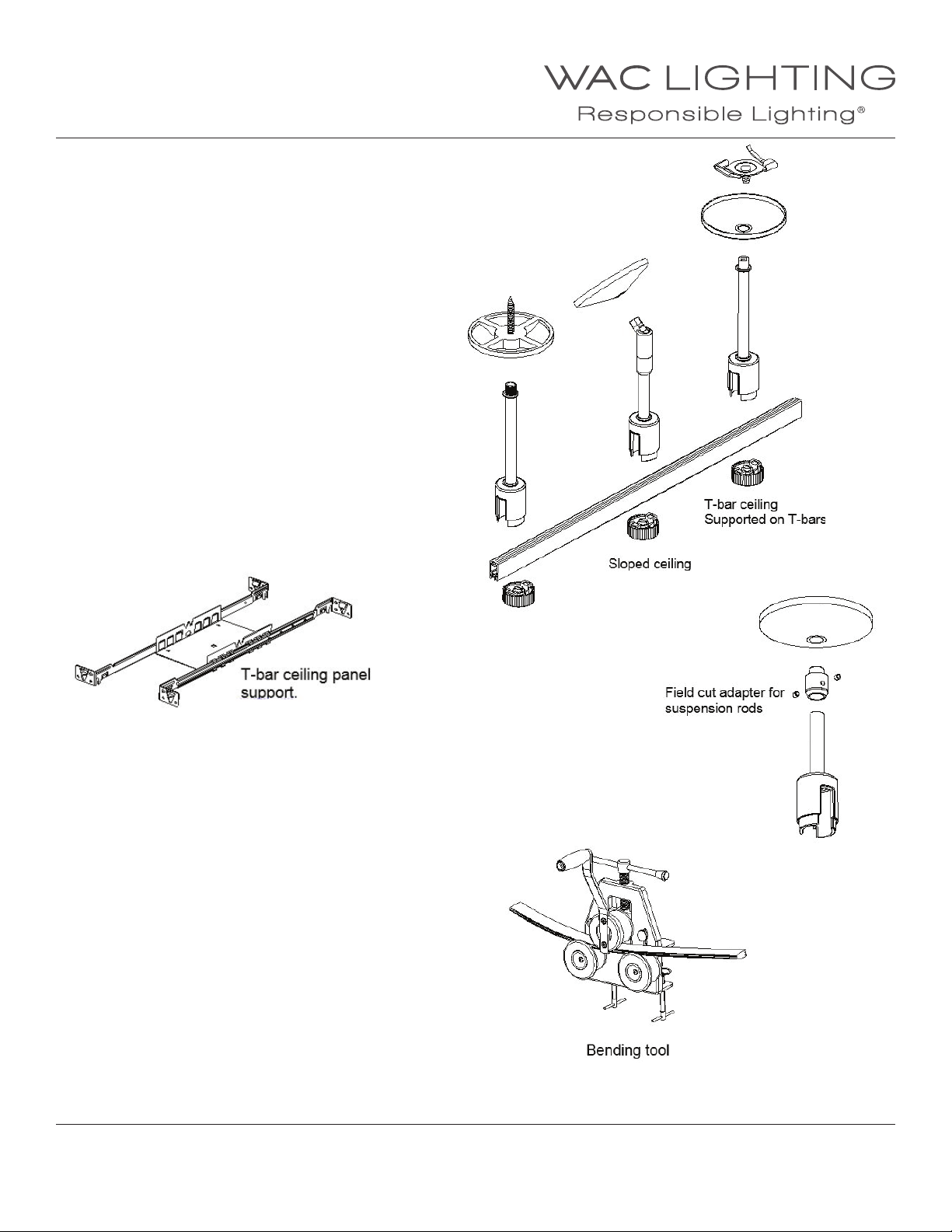
RAIL MOUNTING:
Rail can be mounted on a at surface, a sloped ceiling,
or a suspended ceiling.
1. Use three standos for every 8ft of straight rail.
Curved rail requires more supports.
2. Make a oor lay out with rail or string etc, then use
a plumb line to mark stando locations.
3. For drywall, drill 5/8” holes and insert ceiling anchors
(supplied) through the bases of the standos.
4. For wood surfaces use wood screws through
the stando bases.
5. For “T” bars (It is recommended that “T” bars be
reinforced with Caddy ( clips to the ceiling structure)
Twist “T” bar clip onto the “T” bar.
6. For support at a ceiling panel install a support frame
between two T-bars
Unscrew the cap from the bottom of the rail adapter.
Raise the rail into position and re-install the cap.
Bending Flexrail1™:
1. Hand or machine bendable, minimum radius23”.
2. Before bending: If rail is to be cut and connected to
another rail, a 7/8” end space from the aluminum core
must be maintained to accept an “I” connector.
3. Bend the rail a little at a time starting from the
mid point. Work the rail in stages until you reach
the desired radius.
4. Once rail is bent the wires may become regressed
from the ends. If no other rails are to be connected,
install end caps.
5. If rail is to be connected to another rail, it is necessary
to cut each end ush. This ensures bus wires will
make contact with the connector.
WAC Lighting
www.waclighting.com
Phone (800) 526.2588 • Fax (800) 526.2585
WAC Lighting retains the right to modify the design of our products at any time as part of the company's continuous improvement program. JUNE, 2014
Headquarters/Eastern Distribution Center
44 Harbor Park Drive • Port Washington, NY 11050
Phone (516) 515.5000 • Fax (516) 515.5050
Western Distribution Center
1750 Archibald Ave • Ontario, CA 91761
Phone (800) 526.2588 • Fax (800) 526.2585
Page 4
INSTALLATION INSTRUCTION
Flexrail1™ System - Line Voltage
HM1-T4, HM1-T8
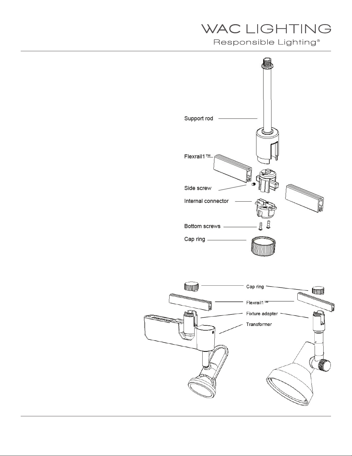
JOINING RAILS:
1. Mount the rod to the ceiling.
2. Unscrew the cap ring, and withdraw the internal
connector by pulling straight down.
3. Loosen the bottom & side screws on the connector.
4. Insert the rail ends into the connector.
5. Tighten the setscrews on both sides, and the
bottom screws.
6. Raise the connector into the upper cover, and
secure with the cap ring.
Note: To ensure good electrical connection,
make sure the bus- wires are always ush with the rail end.
Field Cutting:
1. Rail may be cut with a power or hack saw.
2. File rough edges and brush out and debris.
3. Install end cap over cut end.
Note: A eld cut rail will not be able to join another rail
section unless provisions are made to recess the aluminum
core. It easier to make a eld cut on the end of the last piece.
INSTALLING FIXTURES:
1. Remove the cap ring on the xture adapter.
2. Raise the open end of the adapter to the rail.
3. Re-install the cap ring.
WAC Lighting
www.waclighting.com
Phone (800) 526.2588 • Fax (800) 526.2585
WAC Lighting retains the right to modify the design of our products at any time as part of the company's continuous improvement program. JUNE, 2014
Headquarters/Eastern Distribution Center
44 Harbor Park Drive • Port Washington, NY 11050
Phone (516) 515.5000 • Fax (516) 515.5050
Western Distribution Center
1750 Archibald Ave • Ontario, CA 91761
Phone (800) 526.2588 • Fax (800) 526.2585
 Loading...