

WAC Lighting SCOOP series, 6611, TOWER series, 6621, CHAMBER series Installation Instruction
...
INSTALLATION INSTRUCTION
Bollard Light 12V
6611/6621/6631/6641/6651
SAFETY INSTRUCTION
IMPORTANT: NEVER attempt any work without shutting o the electricity.
• Read all instructions before installing.
• System is intended for installation by a qualied electrician in accordance with the National Electrical Code and local regulations.
• Place the wall switch in the “OFF” position.
• Go to the main fuse box, or circuit breaker. Unscrew the fuse(s) or switch ”OFF” the circuit breaker switch(es) that control the power to the
space that you are working on.
WARNING: Risk of electric shock. Install all luminaires 10 feet (3.05 m) or more from a pool, spa, or fountain.
CAUTION:
All parts must be used as indicated in these instructions. Do not substitute any parts, leave parts out, or use any parts that are worn out
or broken. Failure to follow this instruction could invalidate the ETL/cETL listing of this xture.
AVERTISSEMENT
IMPORTANT : COUPEZ L’ÉLECTRICITÉ AVANT TOUTE MANIPULATION.
• Lisez toutes les instructions avant d’installer.
• Système est destiné à être installé par un électricien qualié en conformité avec le code national de l’électricité et les règlements locaux.
• Placez l’interrupteur mural en position d’arrêt (« OFF »).
• Accédez au panneau central de disjoncteurs ou de fusibles de votre demeure et placez l’interrupteur principal en position d’arrêt (« OFF »).
MISE EN GARDE
Toutes les pièces doivent être utilisées tel qu’il est indiqué dans ces instructions. Ne remplacez pas les pièces, n’en laissez pas de côté et ne les
utilisez pas si elles sont usées ou brisées. Le non-respect de ces instructions peut annuler l’homologation ETL/cETL du luminaire.
*Note: Transformer is required to power the xture. (sold separately)
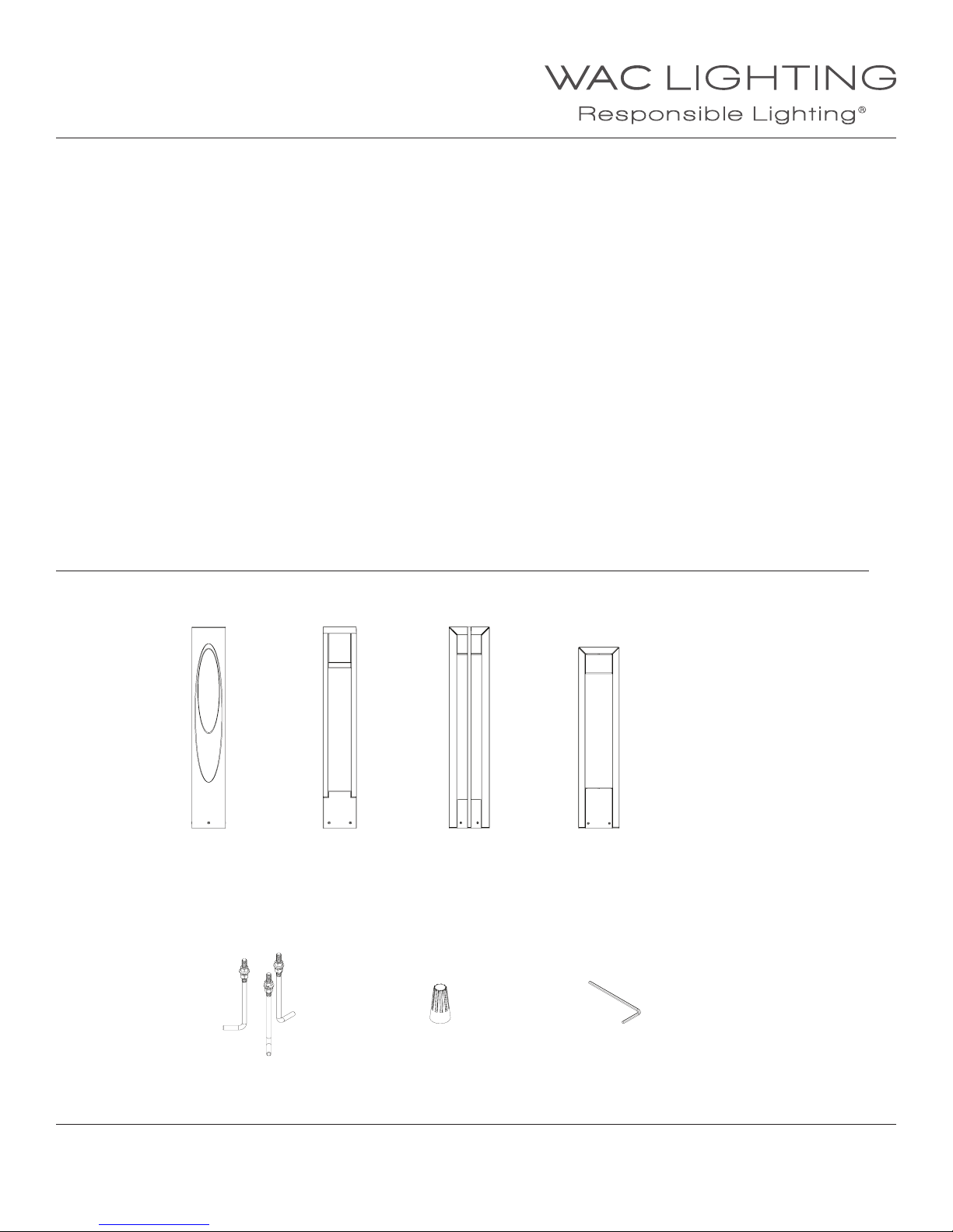
THIS INSTRUCTIONS APPLY TO THE MODELS BELOW:
*Note: Transformer is required to power the xture. (sold separately)
SCOOP
6611
MOUNTING ACCESSORIES (INCLUDED IN BOX)
TOWER
6621
CHAMBER
6631
PARK
6641
PARK
6651
Mounting Stake
Qty: 1pc
waclighting.com
Phone (800) 526.2588
Fax (800) 526.2585
WAC Lighting retains the right to modify the design of our products at any time as part of the company's continuous improvement program. 1
Headquarters/Eastern Distribution Center
44 Harbor Park Drive
Port Washington, NY 11050
Outdoor Rated Wire Nut
Qty: 2pcs
Hex Key
Qty: 1pc
Central Distribution Center
1600 Distribution Ct
Lithia Springs, GA 30122
Western Distribution Center
1750 Archibald Avenue
Ontario, CA 91760

INSTALLATION INSTRUCTION
Bollard Light 12V
6611/6621/6631/6641/6651
INSTALLATION
1. Make sure your main power is o.
2. Excavate a trench for the Mounting Stake.
The Mounting Stake requires approximately a one (1) square
foot hole to facilitate installation.
The excavated should be approximately 14” deep, depending
on your local code. This will allow the hex-head set screw on
the Mounting Stake to remain above ground when the
installation is completed.
3. Secure Fixture Mounting Plate onto the Stake Metal Cap by
using the Stake Mounting Screws.
Bollard Fixture
4. Secure the Stake Metal Cap assembly onto the
Mounting Stake by tighten the Cap Mounting Screw
(Note: Make sure the Fixture Mounting Plate is
Oriented at desired position.)
5. Secure the Bollard Fixture on top of the Fixture
Mounting Plate using the Fixture Mounting Screws.
6. After proper wirings are done by using the outdoor rated wire
nuts, back ll the hole and make sure the xture is leveled and
stable.
7. Turn the main power supply back on and make sure the
xtures light up.
Fixture Mounting Screw
Stake Mounting Screw
Cap Mounting Screw
Mounting Stake
Fixture Mounting Plate
Stake Metal Cap
waclighting.com
Phone (800) 526.2588
Fax (800) 526.2585
WAC Lighting retains the right to modify the design of our products at any time as part of the company's continuous improvement program. 2
Headquarters/Eastern Distribution Center
44 Harbor Park Drive
Port Washington, NY 11050
Central Distribution Center
1600 Distribution Ct
Lithia Springs, GA 30122
Western Distribution Center
1750 Archibald Avenue
Ontario, CA 91760
INSTALLATION INSTRUCTION
Bollard Light 120V/277V
6612 / 6613 / 6622 / 6623 / 6632 / 6633 / 6642 / 6643
SAFETY INSTRUCTION
IMPORTANT: NEVER attempt any work without shutting o the electricity.
• Read all instructions before installing.
• System is intended for installation by a qualied electrician in accordance with the National Electrical Code and local regulations.
• Place the wall switch in the “OFF” position.
• Go to the main fuse box, or circuit breaker. Unscrew the fuse(s) or switch ”OFF” the circuit breaker switch(es) that control the power to the
space that you are working on.
WARNING: Risk of electric shock. Install all luminaires 10 feet (3.05 m) or more from a pool, spa, or fountain.
CAUTION:
All parts must be used as indicated in these instructions. Do not substitute any parts, leave parts out, or use any parts that are worn out
or broken. Failure to follow this instruction could invalidate the ETL/cETL listing of this xture.
AVERTISSEMENT
IMPORTANT : COUPEZ L’ÉLECTRICITÉ AVANT TOUTE MANIPULATION.
• Lisez toutes les instructions avant d’installer.
• Système est destiné à être installé par un électricien qualié en conformité avec le code national de l’électricité et les règlements locaux.
• Placez l’interrupteur mural en position d’arrêt (« OFF »).
• Accédez au panneau central de disjoncteurs ou de fusibles de votre demeure et placez l’interrupteur principal en position d’arrêt (« OFF »).
MISE EN GARDE
Toutes les pièces doivent être utilisées tel qu’il est indiqué dans ces instructions. Ne remplacez pas les pièces, n’en laissez pas de côté et ne les
utilisez pas si elles sont usées ou brisées. Le non-respect de ces instructions peut annuler l’homologation ETL/cETL du luminaire.
*Note: Transformer is required to power the xture. (sold separately)
THIS INSTRUCTIONS APPLY TO THE MODELS BELOW:
SCOOP
6612/6613
MOUNTING ACCESSORIES INCLUDED IN BOX
TOWER
6622/6623
CHAMBER
6632/6633
PARK
6642/6643
Anchor Bolt Kit
Qty: 3pcs
M6000-BOLT-KIT
waclighting.com
Phone (800) 526.2588
Fax (800) 526.2585
WAC Lighting retains the right to modify the design of our products at any time as part of the company's continuous improvement program. 1
Headquarters/Eastern Distribution Center
44 Harbor Park Drive
Port Washington, NY 11050
Outdoor Rated Wire Nut
Qty: 3pcs
7EAC352401
Hex Key
Qty: 1pc
7MPE305001
Metric 3.0 MM
Central Distribution Center
1600 Distribution Ct
Lithia Springs, GA 30122
Western Distribution Center
1750 Archibald Avenue
Ontario, CA 91760

INSTALLATION INSTRUCTION
Bollard Light 120V/277V
6612 / 6613 / 6622 / 6623 / 6632 / 6633 / 6642 / 6643
INSTALLATION
STEP 1:
1. Make sure your main power is o.
2. Prior to installing the xture, secure the anchor bolts
And alignment plate into the cement. Insure the leads,
electrical wires are passing up through the center hole
of the alignment plate.
(Note: Bollard Orientation is critical.
See Bollard Orientation section for detail.)
For shallow base bollards, insure that the anchor bolts
length on top of the cement surface do not exceed
1-1/8” (29mm).
3. After the cement has cured, remove the alignment
Plate and install the Fixture Baseplate until it’s secure. Again,
make sure to feed the leads, electrical wires up through the
center hole of the baseplate.
Use leveler to ensure that the baseplate is leveled.
4. Connect the supply lines from the supply conduit to the
xture input wires per the local electrical code.
(See Wiring Diagram Below)
Tie the wires so that they do not lie on or have
Contact with the ground.
29mm
18”
Alignment Plate
Anchor Bolt
Fixture Housing
Hex Nut
Spring Washer
Flat Washer
Hex Nut
Cement
Bollard Fixture
5. Set the Bollard Fixture onto the Fixture Baseplate
6. Secure the xture by tighten the Fixture Mounting
Screws with Hex Key. Be sure not to crimp any wires between
the Fixture Baseplate and the Fixture Housing Tube.
7. Turn the main power supply back on and make sure the
xtures light up.
8. You have now completed the installation of your xture.
Wiring Diagram
Fig.1
Fixture Fixture Fixture
Wires
Black or
Smooth
Wires
White or
Ribbed
House
Wires
Black
(Hot)
Wires
Bare
Copper
(Ground)
House
Wires
White
(Neutral)
Fixture Mounting Screw
Outdoor Rated Wire Nut
Hex Nut
Fixture Baseplate
Anchor Bolt
Cement
House
Wires
Bare
Copper
(Ground)
waclighting.com
Phone (800) 526.2588
Fax (800) 526.2585
WAC Lighting retains the right to modify the design of our products at any time as part of the company's continuous improvement program. 2
Headquarters/Eastern Distribution Center
44 Harbor Park Drive
Port Washington, NY 11050
Central Distribution Center
1600 Distribution Ct
Lithia Springs, GA 30122
Western Distribution Center
1750 Archibald Avenue
Ontario, CA 91760

INSTALLATION INSTRUCTION
Bollard Light 120V/277V
6612 / 6613 / 6622 / 6623 / 6632 / 6633 / 6642 / 6643
BOLLARD ORIENTATION
6612/6613
6622/6623
Light Area
Light Area
Orientation
Arrow
Alignment
Plate
Orientation
Arrow
Baseplate
Light Area
Light Area
Light Area
waclighting.com
Phone (800) 526.2588
Fax (800) 526.2585
WAC Lighting retains the right to modify the design of our products at any time as part of the company's continuous improvement program. 3
Headquarters/Eastern Distribution Center
44 Harbor Park Drive
Port Washington, NY 11050
Light Area
Alignment
Plate
Orientation
Arrow
Central Distribution Center
1600 Distribution Ct
Lithia Springs, GA 30122
Baseplate
Orientation
Arrow
Western Distribution Center
1750 Archibald Avenue
Ontario, CA 91760

INSTALLATION INSTRUCTION
Bollard Light 120V/277V
6612 / 6613 / 6622 / 6623 / 6632 / 6633 / 6642 / 6643
BOLLARD ORIENTATION
6632/6633
Light Area
Light Area
Light Area
Light Area
Light Area
Light Area
Light Area
Light Area
Alignment
Plate
Alignment
Plate
Baseplate
Baseplate
6642/6643
Light Area Light Area
Orientation
Arrow
Alignment
Plate
Baseplate
Orientation
Arrow
waclighting.com
Phone (800) 526.2588
Fax (800) 526.2585
WAC Lighting retains the right to modify the design of our products at any time as part of the company's continuous improvement program. 4
Headquarters/Eastern Distribution Center
44 Harbor Park Drive
Port Washington, NY 11050
Central Distribution Center
1600 Distribution Ct
Lithia Springs, GA 30122
Western Distribution Center
1750 Archibald Avenue
Ontario, CA 91760
 Loading...