

Page 1
Operator’s Manual
5100030216
Light Tower
LTV6K, LTV6L, LTV8K
60 Hz
Type LTV6K, LTV6L, LTV8K
Document 5100030216
Date
Revision
Language EN
0317
02
Page 2

Copyright notice
© Copyright 2017 by Wacker Neuson Production Americas LLC
All rights, including copying and distribution rights, are reserved.
This publication may be photocopied by the original purchaser of the
machine. Any other type of reproduction is prohibited without express
written permission from Wacker Neuson Production Americas LLC.
Any type of reproduction or distribution not authorized by Wacker
Neuson Production Americas LLC represents an infringement of valid
copyrights. Violators will be prosecuted.
Trademarks
All trademarks referenced in this manual are the property of their
respective owners.
Manufacturer
Wacker Neuson Production Americas LLC
N92W15000 Anthony Avenue
Menomonee Falls, WI 53051 U.S.A.
Tel: (262) 255-0500 · Fax: (262) 255-0550 · Tel: (800) 770-0957
www.wackerneuson.com
Original instructions
This Operator’s Manual presents the original instructions. The original
language of this Operator’s Manual is American English.
Page 3
LTV
wc_gr013759
215429215429
R
51000314545100031454
For electrical
equipment only.
Pour material
electrique seulement.
lbs
Item No.
Type/Model
Serial No.
Rev.
MAX AMB 40~C
RPMhz
MON/YR
MADE IN USA
kW
kg
V
n
A
P.F .
Foreword
SAVE THESE INSTRUCTIONS—This manual contains important instructions for
the machine models below. These instructions have been written expressly by
Wacker Neuson Production Americas LLC and must be followed during inst allation,
operation, and maintenance of the machines.
Machine
identification
Serial number
(S/N)
Machine
documentation
Expectations
for
information in
this manual
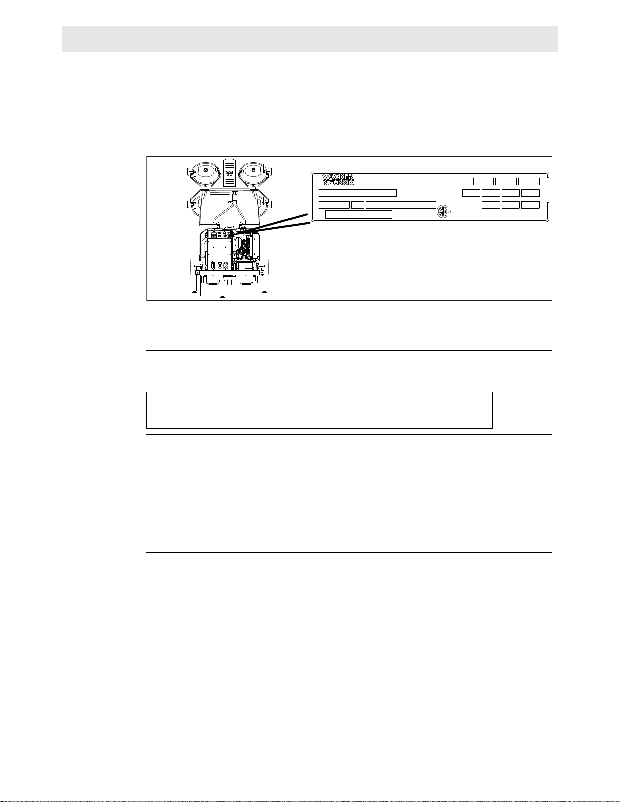
A nameplate listing the model number, item number, revision number, and serial
number is attached to this machine. The location of the nameplate is shown above.
For future reference, record the serial number in the space provided below . You will
need the serial number when requesting parts or service for this machine.
Serial Number:
■ From this point forward in this documentation, Wacker Neuson Production
Americas LLC will be referred to as Wacker Neuson.
■ Keep a copy of the Operator’s Manual with the machine at all times.
■ For spare parts info rmation, please see your Wacker Neuson Dealer, or visit the
Wacker Neuson website at http://www.wackerneuson.com/.
■ When ordering parts or requesting service information, be prepared to provide
the machine model number, item number, revision number, and serial number.
■ This manual provides information and procedures to safely operate and
maintain the above Wacker Neuson model(s). For your own safety and to
reduce the risk of injury, carefully read, understand, and observe all instructions
described in this manual.
■ Wacker Neuson expressly reserves the right to make technical modifications,
even without notice, which improve the performance or safety standards of its
machines.
■ The information contained in this manual is based on machines manufactured
up until the time of publication. Wacker Neuson reserves the right to chan ge any
portion of this information without notice.
■ The illustrations, parts, and procedures in this manual refer to Wacker Neuson
factory-installed components. Your machine may vary depending on the
requirements of your specific region.
wc_tx004428gb_FM10.fm
3
Page 4

LTV
Manufacturer’
s approval
CALIFORNIA
Proposition
65 Warning
This manual contains references to approved parts, attachments, and
modifications. The following definitions apply:
■ Approved parts or attachments are those either manufactured or provided by
Wacker Neuson.
■ Approved modifications are those performed by an authorized Wacker
Neuson service center according to written instructions published by Wacker
Neuson.
■ Unapproved parts, attachments, and modifications are those that do not
meet the approved criteria.
Unapproved parts, attachments, or modifications may have the following
consequences:
■ Serious injury hazards to the operator and persons in the work area
■ Permanent damage to the machine which will not be covered under warranty
Contact your Wacker Neuson dealer immediately if you have questions about
approved or unapproved parts, attachments, or modifications.
Combustion exhaust, some of its constituents, and certain vehicle components
contain or emit chemicals known to the State of California to cause cancer and
birth defects or other reproductive harm.
Laws
pertaining to
spark
arresters
NOTICE: State Health Safety Codes and Public Resources Codes specify that in
certain locations spark arresters be used on internal combustion engines that use
hydrocarbon fuels. A spark arrester is a device designed to prevent accidental
discharge of sparks or flames from the engine exhaust. Spark arresters are
qualified and rated by the United States Forest Service for this purpose. In order to
comply with local laws regarding spark arresters, consult the engine distributor or
the local Health and Safety Administrator.
4
wc_tx004428gb_FM10.fm
Page 5

LTV
Table of Contents
Foreword 3
1 Safety Information 9
1.1 Signal Words Used in this Manual ....................................................... 9
1.2 Machine Description and Intended Use ............................................. 10
1.3 Operating Safety ................................................................................ 11
1.4 Metal Halide Lamp Safety .................................................................. 13
1.5 Service Safety .................................................................................... 14
1.6 Operator Safety while Using Internal Combustion Engines ............... 16
1.7 Safety Guidelines for Lifting the Machine ........................................... 17
1.8 Safety Guidelines for Towing the Machine ......................................... 18
1.9 Reporting Safety Defects ................................................................... 19
2 Labels 20
2.1 Label Locations .................................................................................. 20
2.2 Label Meanings .................................................................................. 22
3 Lifting and Transporting 30
3.1 Lifting the Machine ............................................................................. 30
3.2 Preparing the Machine for Transport on a Truck or Trailer ................ 31
3.3 Before Towing Checklist ..................................................................... 32
3.4 Towing the Machine ........................................................................... 33
3.5 Trailer ................................................................................................. 34
3.6 Flip-up Tongue ................................................................................... 35
4 Machine Setup 36
4.1 Preparing the Machine for First Use ................................................... 36
4.2 Positioning the Machine ..................................................................... 37
4.3 Ground Connection ............................................................................ 38
4.4 Leveling the Trailer—Vertical Mast Light Towers ............................... 39
4.5 Refueling the Machine ........................................................................ 40
4.6 Aiming the Lights—Vertical Mast Light Towers .................................. 41
4.7 Manually Rotating the Light Bar ......................................................... 43
4.8 Raising the Tower—Manual Winch System ....................................... 44
4.9 Lowering the Tower—Manual Winch System .................................... 46
4.10 Raising the Tower—Power Winch System ......................................... 48
4.11 Lowering the Tower—Power Winch System ...................................... 50
wc_bo5100030216_02_FM10TOC.fm
5
Page 6

Table of Contents
5 Operation 52
5.1 Generator Derating ..............................................................................52
5.2 Control Panels and Receptacles—KUBOTA .......................................53
5.3 Control Panels and Receptacles—KOHLER .......................................54
5.4 Control Panel and Receptacles—DeepSea ........................................55
5.5 Machine Monitoring – DeepSea ..........................................................56
5.6 Alarms and Shut-Down Conditions – DeepSea ..................................58
5.7 Resetting the Maintenance Timers – DeepSea ...................................60
5.8 Before Starting ....................................................................................61
5.9 Starting, Operating, Stopping the Machine—KUBOTA .......................62
5.10 Starting, Operating, and Stopping the Machine—KOHLER ................64
5.11 Starting, Operating, Stopping the Machine—DeepSea .......................66
5.12 Auto Mode (Remote Run) ...................................................................68
5.13 Engine - Jump-Starting ........................................................................70
5.14 Emergency Shutdown Procedure ........................................................73
5.15 Using the Convenience Receptacles—60 Hz .....................................74
LTV
6 Factory-Installed Options 75
6.1 Cold Weather Package .......................................................................75
6.2 Engine Block Heater ............................................................................75
6.3 Battery Blanket ....................................................................................76
6.4 Oil Pan Heater .....................................................................................76
6.5 Fuel and Water Separator ...................................................................77
6.6 Positive Air Shutoff ..............................................................................77
6.7 Shore Power ........................................................................................77
7 General Maintenance 78
7.1 Preparing for Maintenance ..................................................................78
7.2 Periodic Maintenance Schedule ..........................................................79
7.3 Cleaning the Machine ..........................................................................80
7.4 Inspecting the Machine .......................................................................80
7.5 Maintaining the Trailer .........................................................................81
7.6 Maintaining the Battery ........................................................................82
7.7 Removing and Replacing Lamps ........................................................83
7.8 Long-Term Storage .............................................................................85
7.9 Machine Disposal and Decommissioning ............................................86
wc_bo5100030216_02_FM10TOC.fm
6
Page 7

LTV
Table of Contents
8 Engine Maintenance: Kubota D1005 / D1105 87
9 Engine Maintenance: KOHLER 90
10 Troubleshooting 95
11 Technical Data 97
11.1 Engine—KUBOTA .............................................................................. 97
11.2 Engine—KOHLER .............................................................................. 98
11.3 Generator ........................................................................................... 99
11.4 Machine ............................................................................................ 100
11.5 Radiation Compliance ...................................................................... 101
11.6 Dimensions—LTV6K, LTV8K, LTV6L .............................................. 101
12 Emissions Control Systems Information
and Warranty: KUBOTA
12.1 Emission Control System Background Information .......................... 102
12.2 Limited Defect Warranty for Wacker Neuson Emission Control
Systems ............................................................................................ 103
13 Emissions Control Systems Information
and Warranty: KOHLER
13.1 Emission Control System Background Information .......................... 106
13.2 Limited Defect Warranty for Exhaust Emission Control System ....... 107
102
106
wc_bo5100030216_02_FM10TOC.fm
7
Page 8

Table of Contents
LTV
wc_bo5100030216_02_FM10TOC.fm
8
Page 9
LTV Safety Information
1 Safety Information
1.1 Signal Words Used in this Manual
This manual contains DANGER, WARNING, CAUTION, NOTICE, and NOTE
signal words which must be followed to reduce the possibility of personal injury,
damage to the equipment, or improper service.
This is the safety alert symbol. It is used to alert you to potential personal hazards.
► Obey all safety messages that follow this symbol.
DANGER
DANGER indicates a hazardous situation which, if not avoided, will result in death
or serious injury.
► To avoid death or serious injury from this type of hazard, obe
messages that follow this signal word.
y all safety
WARNING
WARNING indicates a hazardous situation which, if not avoided, could result in
death or serious injury.
► To avoid possible death or serious injury from this type of hazard,
messages that follow this signal word.
CAUTION
CAUTION indicates a hazardous situation which, if not avoided, could result in
minor or moderate injury.
► To avoid possible minor or moderate injury from this type of hazard,
safety messages that follow this signal word.
NOTICE: Used without the safety alert symbol, NOTICE indicates a situation
which, if not avoided, could result in property damage.
Note: A Note contains additional information important to a procedure.
obey all safety
obey all
wc_si000704gb_FM10.fm
9
Page 10

Safety Information LTV
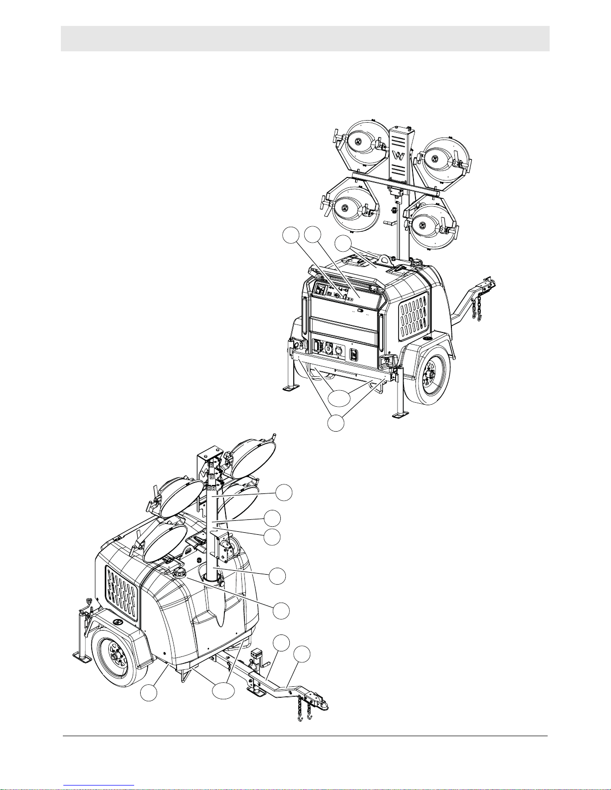
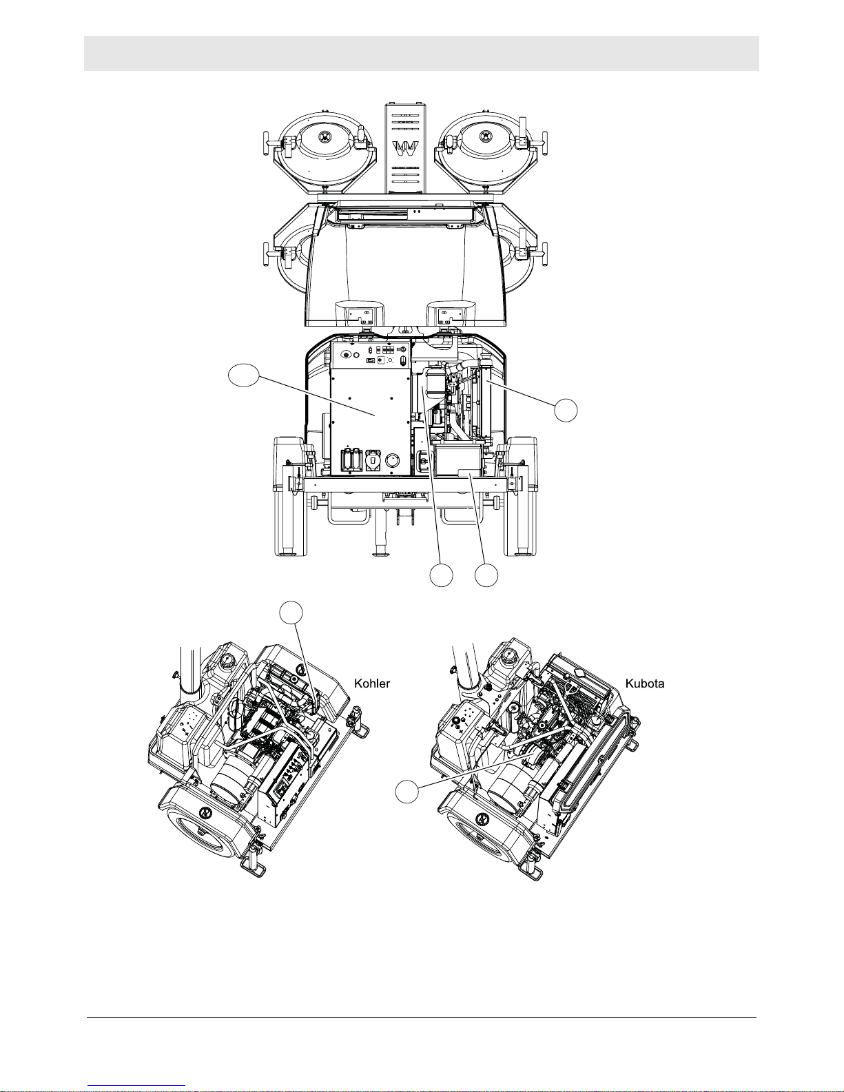
1.2 Machine Description and Intended Use
Machine
description
Intended use
This machine is a mobile, trailer-mounted light tower. The Wacker Neuson Light
Tower consists of a trailer with a cabinet containing a diesel engine, a fuel tank, a
control panel, and an electric alternator. A telescoping tower with four metal halide
or LED lights is vertically mounted to the top of the cab inet. As the engine runs, the
generator converts mechanical energy into electric power. The metal halide or LED
lights run off this power. Receptacle(s) are also provided to power auxiliary loads.
The operator uses the control panel to operate and monitor the machine.
This machine is intended for the illumination of outdoor areas. This machine is also
intended for the purpose of supplying electrical power to connected loads. Refer to
the machine specifications for the output voltage and frequency, and for the
maximum output power limit of this machine.
This machine has been designed and built strictly for the intended use described
above. Using the machine for any other purpose could permanently damage the
machine or seriously injure the operator or other persons in the area. Machine
damage caused by misuse is not covered under warranty. The following are some
examples of misuse:
■ Connecting a load that has voltage and frequency requirements that are
incompatible with the machine output
■ Overloading the machine with a device that draws excessive power during
either continuous running or start-up
■ Operating the machine in a manner that is inconsistent with all federal, state,
and local codes and regulations
■ Using the machine as a ladder, support, or work surface
■ Using the machine to carry or transport passengers or equipment
■ Using the machine to tow other machines (unless factory equipped)
■ Using the machine as a hoist, or hanging items from the tower
■ Operating the machine outside of factory specifications
■ Operating the machine in a manner inconsistent with all warnings found on the
machine and in the Operator’s Manual
This machine has been designed and built in accordance with the latest global
safety standards. It has been carefully engineered to eliminate hazards as far as
practicable and to increase operator safety through protective guards and labeling.
However, some risks may rema in even after protective measures have been t aken.
They are called residual risks. On this machine, they may include exposure to:
■ Heat, noise, exhaust, and carbon monoxide from the engine
■ Heat from the lights
■ Ultraviolet radiation from the lights
■ Fire hazards from improper refueling techniques
■ Fuel and its fumes
■ Electric shock and arc flash
■ Personal injury from improper lifting the trailer tongue
■ Glare from lights (lights may blind drivers of nearby motor vehicles if the lights
are incorrectly positioned)
10
wc_si000704gb_FM10.fm
Page 11

LTV Safety Information
■ Typical hazards related to towing a trailer on roads and highways
To protect yourself and others, make sure you thoroughly read and understand the
safety information presented in this manual before operating the machine.
1.3 Operating Safety
Operator
training
Operator
qualifications
Application
area
Before operating the machine:
■ Read and understand the operating instructions contained in all manuals
delivered with the machine.
■ Familiarize yourself with the location and proper use of all controls and safety
devices.
■ Contact Wacker Neuson for additional training if necessary.
When operating this machine:
■ Do not allow improperly trained people to operate the machine. People
operating the machine must be familiar with the potential risks and hazards
associated with it.
Only trained personnel are permitted to start, operate, and shut down the machine.
They also must meet the following qualifications:
■ Have received instruction on how to properly use the machine
■ Are familiar with required safety devices
The machine must not be accessed or operated by:
■ Children
■ People impaired by alcohol, drugs or prescription drugs
Be aware of the application area.
■ Keep unauthorized personnel, children, and pets away from the machine.
■ Remain aware of changing positions and the movement of other equipment and
personnel in the application area/job site.
■ Identify whether special hazards exist in the application area, such as toxic
gases or unstable ground conditions, and take appropriate action to eliminate
the special hazards before using the machine.
Be aware of the application area.
■ Do not operate the machine in areas that contain flammable objects, fuels, or
products that produce flammable vapors.
Safety
devices,
controls, and
attachments
Only operate the machine when:
■ All safety devices and guards are in place and in working order.
■ All controls operate correctly.
■ The machine is set up correctly according to the instructions in the Operator’s
Manual.
■ The machine is clean.
■ The machine’s labels are legible.
To ensure safe operation of the machine:
wc_si000704gb_FM10.fm
11
Page 12

Safety Information LTV
■ Do not operate the machine if any safety devices or guards are missing or
inoperative.
■ Do not modify or defeat the safety devices.
■ Only use accessories or attachments that are approved by Wacker Neuson.
Safe
operating
practices
Personal
Protective
Equipment
(PPE)
Before
Starting
When operating this machine:
■ Remain aware of the machine’s moving parts. Keep hands, feet, and loose
clothing away from the machine’s moving parts.
When operating this machine:
■ Do not operate a machine in need of repair.
■ Do not consume the operating fluids used in this machine. Depending on your
machine model, these operating fluids may include water, wetting agents, fuel
(gasoline, diesel, kerosene, propane, or natural gas), oil, coolant, hydraulic fluid,
heat transfer fluid (propylene glycol with additives), battery acid, or grease.
Wear the following Personal Protective Equipment (PPE) while operating this
machine:
■ Close-fitting work clothes that do not hinder movement
■ Safety glasses with side shields
■ Hearing protection
■ Safety-toed footwear
■ Be sure the machine is on a firm, level surface and will not tip, roll, slide, or fall
while operating.
■ Never connect the machine to other power sources, such as supply mains of
power companies.
■ Never use the machine if the insulation on the electrical cord is cut or worn
through.
■ Never raise the tower or operate the machine in high winds.
■ The tower extends up to 7 m (23 ft.). Make sure the area above the trailer is
open and clear of overhead wires and obstructions.
Operation
■ Keep the area under and around the lights clear of people while raising and
lowering the tower.
■ Do not move the machine while it is operating or while the tower is raised.
After Use
■ Stop the engine when the machine is not being operated.
■ Close the fuel valve on engines equipped with one when the machine is not
being operated.
■ Ensure that the machine will not tip over, roll, slide, or fall when not being
operated.
■ Store the machine properly when it is not being used. The machine should be
stored in a clean location out of the reach of children.
■ Lower the tower when not in use, or if high winds or electrical storms are
expected in the area.
12
wc_si000704gb_FM10.fm
Page 13

LTV Safety Information
■ The lamps become extremely hot during use! Allow the lamp and fixture to cool
10–15 minutes before handling.
1.4 Metal Halide Lamp Safety
Description
Operating
safety
The lamps provided with the machine are electric discharge lamps. They are
designed for use with metal halide ballasts only, and require time to reach full
brightness on initial startup and after a power interruption. These lamps comply
with FDA regulation performance standards 21 CFR 1040-30.
WARNING
Personal injury hazard. Broken or punctured lamps can cause serious skin burns
and eye inflammation from shortwave ultraviolet radiation.
► Do not operate the machine if a lamp is damaged.
► Replace damaged lamps immediately.
Replace damaged lamps according to the instructions in section Removing and
Replacing Lamps.
wc_si000704gb_FM10.fm
13
Page 14

Safety Information LTV
1.5 Service Safety
Service
training
Precautions
Before servicing or maintaining the machine:
■ Read and understand the instructions contained in all manuals delivered with
the machine.
■ Familiarize yourself with the location and proper use of all controls and
protective devices.
■ Only trained personnel shall troubleshoot or repair problems occurring with the
machine.
■ Contact Wacker Neuson for additional training if necessary.
When servicing or maintaining this machine:
■ Do not allow untrained or improperly trained people to service or maintain the
machine. Personnel servicing or maintaining the machine must be familiar with
the associated potential risks and hazards.
■ Maintenance items that can be performed by the operator are listed in this
manual. Other repairs should be performed by a qualified technician. Repairs
can be hazardous if not performed correctly. Contact your Wacker Neuson
dealer service department for additional information or for repairs to your
machine.
When servicing or maintaining the machine:
■ Read and understand the service procedures before performing any service to
the machine.
■ All adjustments and repairs must be completed before operating the machine.
Do not operate the machine with a known problem or deficiency.
■ All repairs and adjustments shall be completed by a qualified technician.
■ Turn off the machine before performing maintenance or making repairs.
■ Remain aware of the machine’s moving parts. Keep hands, feet, and loose
clothing away from the machine’s moving parts.
■ Re-install the safety devices and guards after repair and maintenance
procedures are complete.
■ Before servicing the machine, make sure the engine start switch is turned to the
OFF position, the circuit breakers are open (off), and the negative terminal on
battery is disconnected. Do not perform even routine service (oil/filter changes,
cleaning, etc.) unless all electrical components are shut down.
■ Always turn off light circuit breakers and shut down engine before disconnecting
light fixtures or changing light bulbs.
Machine
modifications
When servicing or maintaining the machine:
■ Use only accessories/attachments that are approved by Wacker Neuson.
When servicing or maintaining the machine:
■ Do not defeat safety devices.
■ Do not modify the machine without the express written approval of Wacker
Neuson.
14
wc_si000704gb_FM10.fm
Page 15

LTV Safety Information
Replacing
parts and
labels
Cleaning
Personal
Protective
Equipment
(PPE)
■ Replace worn or damaged components.
■ Replace all missing and hard-to-read labels.
■ When replacing electrical components, use components that are identical in
rating and performance to the original components.
■ When replacement parts are required for this machine, use only Wacker
Neuson replacement parts or those p arts equivalent to the original in a ll types of
specifications, such as physical dimensions, type, strength, and material.
When cleaning and servicing the machine:
■ Keep machine clean and free of debris such as leaves, paper, cartons, etc.
■ Keep labels legible.
■ Clean with soapy water only.
When cleaning the machine:
■ Do not clean the machine while it is running.
■ Never use gasoline or other types of fuels or flammable solvents to clean the
machine. Fumes from fuels and solvents can become explosive.
Wear the following Personal Protective Equipment (PPE) while servicing or
maintaining this machine:
■ Close-fitting work clothes that do not hinder movement
■ Safety glasses with side shields
■ Hearing protection
■ Safety-toed footwear
In addition, before servicing or maintaining the machine:
■ Tie back long hair.
■ Remove all jewelry (including rings).
wc_si000704gb_FM10.fm
15
Page 16
Safety Information LTV
1.6 Operator Safety while Using Internal Combustion Engines
WARNING
Internal combustion engines present special hazards during operation and fueling.
Failure to follow the warnings and safety standards could result in severe injury or
death.
► Read and follow the warning instructions in the engine owner’s manual and the
safety guidelines below.
DANGER
Exhaust gas from the engine contains carbon monoxide, a deadly poison.
Exposure to carbon monoxide can kill you in minutes.
► NEVER operate the machine inside an enclosed area, such as a tunnel, unless
adequate ventilation is provided through items such as exhaust fans or hoses.
Operating
safety
Refueling
safety
When running the engine:
■ Keep the area around the exhaust pipe free of flammable materials.
■ Check the fuel lines and the fuel tank for leaks and cracks before starting the
engine. Do not run the machine if fuel leaks are present or the fuel lines are
loose.
When running the engine:
■ Do not smoke while operating the machine.
■ Do not run the engine near sparks or open flames.
■ Do not touch the engine or muffler while the engine is running or immediately
after it has been turned off.
■ Do not operate a machine when its fuel cap is loose or missing.
■ Do not start the engine if fuel has spilled or a fuel odor is present. Move the
machine away from the spill and wipe the machine dry before starting.
When refueling the engine:
■ Clean up any spilled fuel immediately.
■ Refill the fuel tank in a well-ventilated area.
■ Re-install the fuel tank cap after refueling.
■ Use suitable tools for refueling (for example, a fuel hose or funnel).
When refueling the engine:
■ Do not smoke.
■ Do not refuel a hot or running engine.
■ Do not refuel the engine near sparks or open flames.
16
wc_si000704gb_FM10.fm
Page 17

LTV Safety Information
1.7 Safety Guidelines for Lifting the Machine
When lifting the machine:
■ Make sure slings, chains, hooks, ramps, jacks, forklifts, cranes, hoists, and any
other type of lifting device used is attached securely and has enough weightbearing capacity to lift or hold the machine safely. See chapter Technical Data
for machine weight.
■ Remain aware of the location of other people when lifting the machine.
■ Only use the lifting points and tie-downs described in the Operator’s Manual.
■ Make sure the transporting vehicle has sufficient load cap acity and platform size
to safely transport the machine.
To reduce the possibility of injury:
■ Do not stand under the machine while it is being lifted or moved.
■ Do not get onto the machine while it is being lifted or moved.
wc_si000704gb_FM10.fm
17
Page 18

Safety Information LTV
1.8 Safety Guidelines for Towing the Machine
WARNING
Risk of severe injury or death. Improper trailer condition and towing technique can
lead to an accident.
► Obey the instructions below to reduce the risk of an accident.
When towing the machine:
■ Do not tow the machine if the towing vehicle’s hitch or the trailer’s coupler are
damaged.
■ Do not tow the machine if safety chains are damaged.
■ Do not tow the machine if any of the trailer’s lug nuts are loose or missing.
■ Do not tow the machine if the trailer’s tires have less than 1/16 inch (1.5 mm) of
tread.
■ Do not tow the machine if trailer tires are underinflated.
■ Do not tow the machine unless the trailer’s brakes are functioning properly.
■ Do not tow the machine if trailer lighting is not functioning properly.
■ Do not exceed the trailer manufacturer’s speed limitations of 89 km/h (55 mph).
When towing the machine:
■ Only tow the machine when the trailer’s lug nuts are properly torqued.
■ Only tow the machine when the trailer’s tires are properly inflated.
■ Only tow the machine when all trailer lights are functioning correctly.
■ Only tow the machine when the trailer’s safety chains are connected to the
towing vehicle in a crisscross pattern.
■ Maintain extra distance between the towing vehicle and other vehicles.
■ Avoid soft shoulders, curbs, and sudden lane changes.
■ Abide by all licensing requirements for your area.
If you have not driven a towing vehicle with a trailer before, practice turning,
stopping, and backing up the towing vehicle with the trailer in an area away from
traffic. Only drive the towing vehicle with the trailer when you are confident in your
ability to do so.
18
wc_si000704gb_FM10.fm
Page 19

LTV Safety Information
1.9 Reporting Safety Defects
If you believe your trailer has a defect which could cause a crash or could cause
injury or death, you should immediately inform the National Highway Traffic Safety
Administration (NHTSA) in addition to notifying Wacker Neuson.
If NHTSA receives similar complaints, it may open an investigation; and if it finds
that a safety defect exists in a group of trailers, it may order a recall and remedy
campaign. However, NHTSA cannot become involved in individual problems
between you, your dealer, or Wacker Neuson.
To contact NHTSA, you may either contact the Vehicle Safety Hotline toll-free at
1-888-327-4236 (TTY: 1-800-424-9153); go to http://www.safercar.gov; or write to:
Administrator
NHTSA
1200 New Jersey Avenue S.E.
Washington, DC 20590
You can also obtain other information about your motor vehicle safety from
http://www.safercar.gov
wc_si000704gb_FM10.fm
19
Page 20
Labels LTV
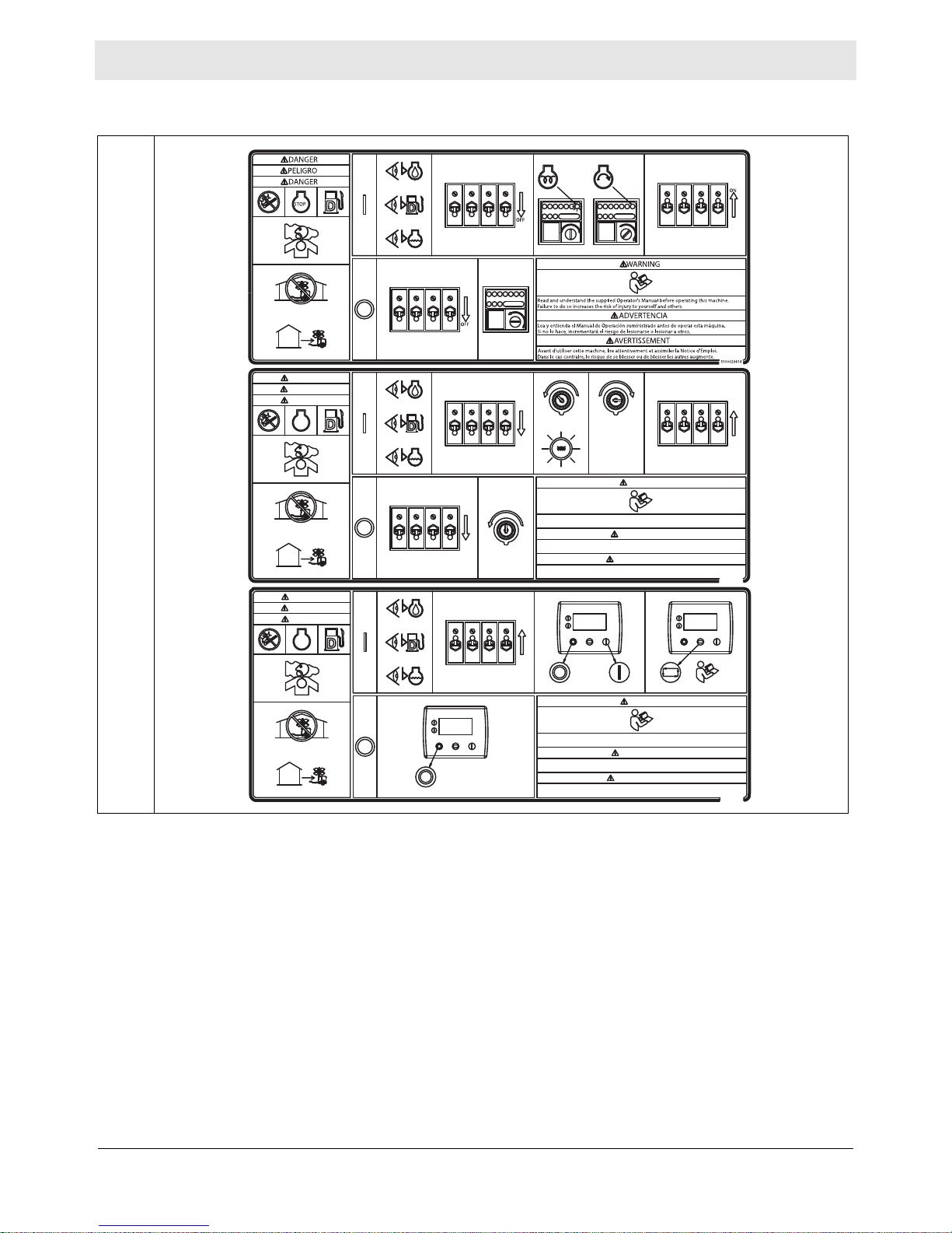
2 Labels
2.1 Label Locations
A
N
B
G
H
D,E
C
F
I
J
L
M
K
D,E
wc_gr013742
wc_si001039gb_FM10.fm
20
Page 21
LTV Labels
wc_gr013743
W
W
V
T
U
Q,S
wc_si001039gb_FM10.fm
21
Page 22
Labels LTV
AUTO
2.2 Label Meanings
A
DANGER
PELIGRO
DANGER
STOP
DANGER
PELIGRO
DANGER
STOP
START
OFF
15 SEC. MAX.
ARRANQUE
15 SEG. MAX.
DEMARRAGE
15 SEC. MAX.
WARNING
Read and understand the supplied Operator's Manual before operating this machine.
Failure to do so increases the risk of injury to yourself and others.
OFF
Lea y entienda el Manual de Operación suministrado antes de operar esta máquina.
Si no lo hace, incrementará el riesgo de lesionarse o lesionar a otros.
Avant d'utiliser cette machine, lire attentivement et assimiler la Notice d'Emploi.
Dans le cas contraire, le risque de se blesser ou de blesser les autres augmente.
ON
ADVERTENCIA
AVERTISSEMENT
AUTO AUTO
21
AUTO
ON
5100029814
WARNING
Read and understand the supplied Operator's Manual before operating this machine.
AUTO
Failure to do so increases the risk of injury to yourself and others.
Lea y entienda el Manual de Operación suministrado antes de operar esta máquina.
Si no lo hace, incrementará el riesgo de lesionarse o lesionar a otros.
Avant d'utiliser cette machine, lire attentivement et assimiler la Notice d'Emploi.
Dans le cas contraire, le risque de se blesser ou de blesser les autres augmente.
ADVERTENCIA
AVERTISSEMENT
5100031361
22
wc_si001039gb_FM10.fm
Page 23
LTV Labels
177123
5100031248
A See Operator’s Manual for light fixture information and troubleshooting.
BEFORE STARTING THE ENGINE:
1. Check levels of:
■ Engine oil
■ Fuel
■ Coolant
2. Move the circuit breakers to the OFF position.
TO START THE ENGINE:
1. On the engine control panel, turn the key switch to the PREHEAT position; the indicator light will
illuminate during preheating.
2. When the PREHEAT indicator light goes out, turn the key switch to the START position for a
maximum of 15 seconds.
3. When the engine is running, move the circuit breakers to the ON position.
TO SHUT DOWN THE MACHINE:
1. Move the circuit breakers to the OFF position.
2. Turn the key switch to the OFF position to stop the engine.
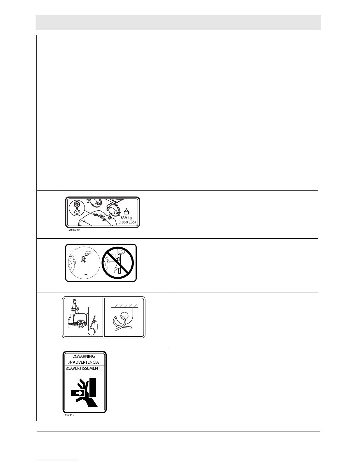
B NOTICE
Lifting point
C Insert jack locking pin before extending jack.
D,E Fork lift pocket
Tie-down point
F WARNING
Avoid crushing area.
wc_si001039gb_FM10.fm
23
Page 24
Labels LTV
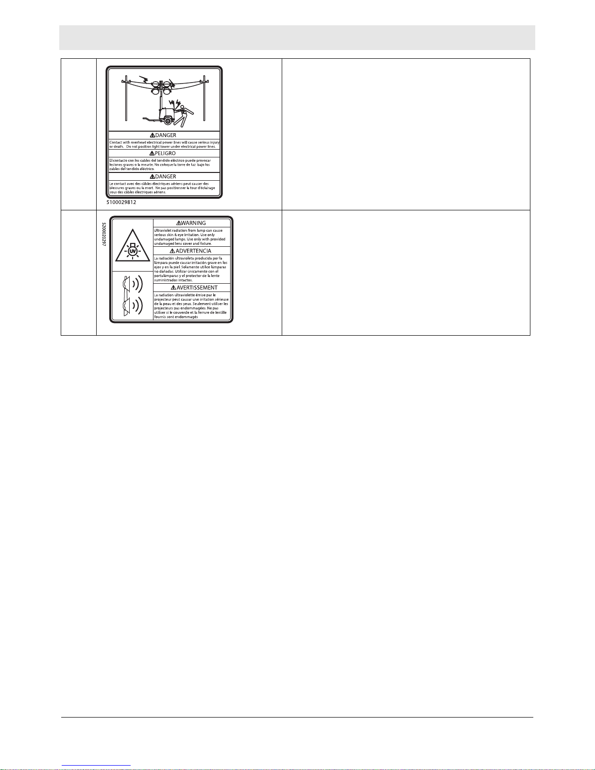
G DANGER
Contact with overhead electrical power lines will cause
serious injury or death. Do not position Light Tower
under electrical power lines.
H WARNING
Ultraviolet radiation from lamp can cause serious skin
and eye irritation. Use only with undamaged lamps. Use
only with provided undamaged lens cover and fixture.
24
wc_si001039gb_FM10.fm
Page 25
LTV Labels
SEULEMENT CARBURANT DE
SOUFRE ULTRA BAS.
5100031249
SOLAMENTE COMBUSTIBLE DE
ULTRABAJO CONTENIDO DE AZUFRE.
ULTRA LOW SULFUR FUEL ONLY
NOTICE
AVISO
AVIS
PELIGRO
DANGER
ULSD-S15
STOP
DANGER
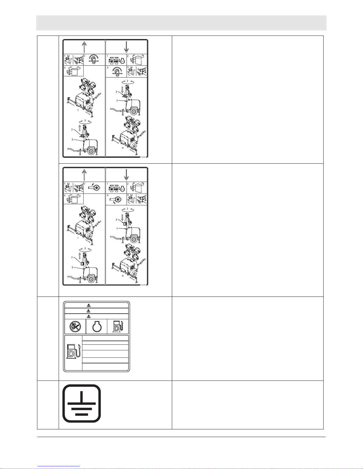
I Manual Winch
TO RAISE TOWER
1. Lift pins and extend outriggers
2. Raise tower with winch.
3. Loosen mast rotation knob to aim tower. Tighten
knob when tower is aimed.
TO LOWER TOWER
1. Turn off breakers and engine.
2. Loosen mast rotation knob an d rotate tower forward.
Tighten knob when tower is facing forward.
3. Lower tower with winch.
4. Lift pins and retract outriggers.
Power Winch
TO RAISE TOWER
1. Lift pins and extend outriggers
2. Raise tower with switch.
3. Loosen mast rotation knob to aim tower. Tighten
knob when tower is aimed.
TO LOWER TOWER
1. Turn off breakers and engine.
2. Loosen mast rotation knob and rotate tower forwa rd.
Tighten knob when tower is facing forward.
3. Lower tower with switch.
4. Lift pins and retract outriggers.
J Ultra low sulfur fuel only
K Electrical ground
wc_si001039gb_FM10.fm
25
Page 26
Labels LTV
5100031166
WARNING
ADVERTENCIA
AVERTISSEMENT
WARNING
ADVERTENCIA
AVERTISSEMENT
5
3
85 lb-ft
115 Nm
4
2
1
5100031252
ADVERTENCIA
WARNING
ADVERTENCIA
WARNING
AVERTISSEMENT
AVERTISSEMENT
5
3
85 lb-ft
115 Nm
4
2
1
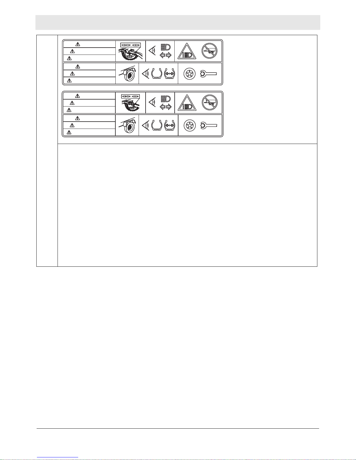
L
WARNING
(On trailer, if equipped)
Lights can prevent trailer from being hit by other vehicles. You must:
1. CONNECT trailer and tow vehicle electrical connectors.
2. CHECK all lights: tail lights, turn signals, and brake lights.
3. DO NOT TOW if lights are not working.
WARNING
Tire, wheel or lug nut failure can cause loss of control. Before towing, you must CHECK:
1. Tire pressure and tread.
2. Tires and wheels for damage.
3. Lug nuts for tightness. Lug nuts should be tighte ned to 85 f t-lbs. For new and remounted wheels,
re-tighten lug nuts at the first 10, 25, and 50 miles of driving.
26
wc_si001039gb_FM10.fm
Page 27

LTV Labels
839 kg
(1850 LBS)
WARNING
AVERTISSEMENT
ADVERTENCIA
5100031165
WARNING
AVERTISSEMENT
ADVERTENCIA
839 kg
(1850 LBS)
WARNING
ADVERTENCIA
AVERTISSEMENT
5100031251
ADVERTENCIA
WARNING
AVERTISSEMENT
5100029813
160604160604
M
WARNING
(On trailer, if equipped)
Uncoupling will cause trailer to come loose from tow vehicle. You must:
1. CHECK that ball LOAD RATING is same as or greater than coupler LOAD RATING.
2. CHECK that ball SIZE is same as coupler.
3. CLOSE COUPLER CLAMP on ball.
4. LIFT coupler upwards to test that it will not separate from ball.
5. LOCK coupler clamp with pin or padlock.
WARNING
(On trailer, if equipped)
ALWAYS use safety chains. Chains hold trailer if connection fails. You must:
1. CROSS chains underneath coupler.
2. ALLOW slack for trailer to turn.
3. ATTACH chain hooks securely to tow vehicle.
N Light cover
P (if equipped)
wc_si001039gb_FM10.fm
Skid drain access point
27
Page 28
Labels LTV
Operation of This Equipment May Create Sparks That Can
Start Fires Around Dry Vegetation. A Spark Arrestor May be
Required. The Operator Should Contact Local Fire Agencies
For Laws or Regulations Relating to Fire Prevention
Requirements.
Choque eléctrico y arco voltaico de cortocircuito pueden
causar heridas personales o muerte. Dispositivo de
almacenaje eléctrico en el interior. Para trabajos de
mantenimiento o para abrir la caja eléctrica consulte
a un electricista capacitad
Électrochoc et arc de court-circuit peuvent résulter en
blessures graves ou mort. Dispositif électrique de stockage
à l'intérieur. Contacter un électricien qualié pour réparer
ou ouvrir le boitier électrique.
AVERTISSEMENT
Electric shock and arc ash can cause serious
injury or death. Electrical storage device
within. Contact a qualied electrician for
service or to open electrical box.
Per CAL. PRC. CODE ÿ 4442.6(a)
WARNING
ADVERTENCIA
5100031250
WARNING
UTILITY 159116UTILITY 159116
U.S.PAT.Nos.: 6012285, 6471476, U.S.PAT.Nos.: 6012285, 6471476,
D416858, D454357 OTHER U.S. AND D416858, D454357 OTHER U.S. AND
FOREIGN PATENTS PENDINGFOREIGN PATENTS PENDING
178775178775
ADVERTENCIAADVERTENCIA
AVERTISSEMENTAVERTISSEMENT
WARNINGWARNING
114891114891
AVERTISSEMENTAVERTISSEMENT
WARNINGWARNING
ADVERTENCIAADVERTENCIA
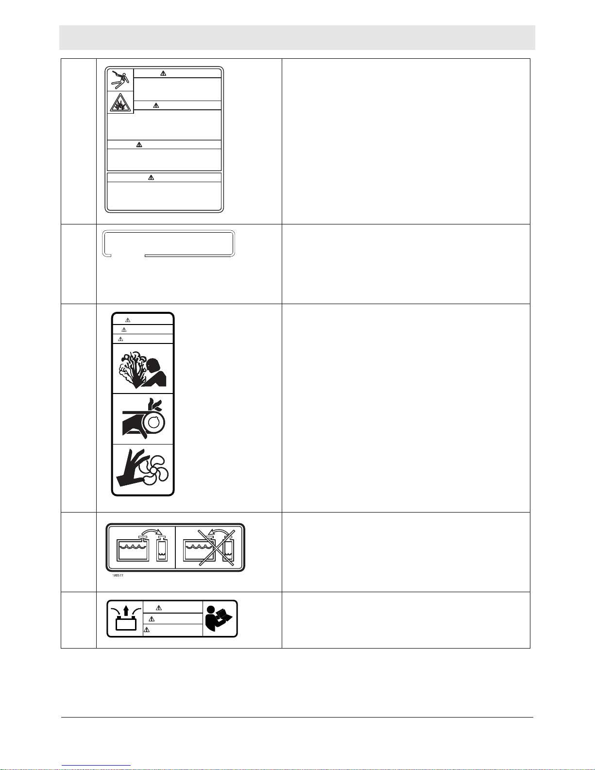
Q WARNING
Electric shock and arc flash can cause serious injury or
death. Electrical storage device within. Contact a
qualified electrician for service or to open electrical box.
WARNING
Operation of this equipment may create sparks that can
start fires around dry vegetation. A spark arrester may
be required. The operator should contact local fire
agencies for laws or regulations relating to fire
prevention requirements.
S This machine may be covered by one or more patents.
T WARNING
■ Pressurized contents. Do not open when hot!
■ Pinching / cutting hazards.
■ Rotating machinery.
U Coolant overflow bottle only, not a return system.
V WARNING
Disconnect battery before servicing.
Read the Operator’s Manual.
wc_si001039gb_FM10.fm
28
Page 29

LTV Labels
AVERTISSEMENTAVERTISSEMENT
52000058905200005890
ADVERTENCIAADVERTENCIA
WARNINGWARNING
MANUFACTURED BY/FABRIQUÉ PAR: A
DATE: B GVWR/PNBV: C
GAWR/PNBE (ALL AXLES) TIRE/PNEU RIM/JANTE KPA (PSI/LPC) SGL/DUAL
D E F G H
THIS VEHICLE CONFORMS TO ALL APPLICABLE STANDARDS PRESCRIBED UNDER THE CANADIAN
MOTOR VEHICLE SAETY REGULATIONS IN EFFECT ON THE DATE OF MANUFACTURE. /CE
VÉHICULE EST CONFORME À TOUTES LES NORMES QUI LUI SONT APPLICABLES EN VERTU DU
RÉGLEMENT SUR LA SÉCURITÉ DES VÉHICULES AUTOMOBILES DU CANADA EN VIGUEUR À LA
DATE DE SA FABRICATION.
THIS VEHICLE CONFORMS TO ALL APPLICABLE U.S. FEDERAL MOTOR VEHICLE SAFETY
STANDARDS (FMVSS) IN EFFECT ON THE DATE OF MANUFACTURE SHOWN ABOVE
V.I.N./N.I.V. I TYPE/TYPE DE VEHICULE: J
COLD INFL. PRESS./PRESS.
DE GONF À FROID
174993
W WARNING
Explosion hazard.
■ Do not use evaporative starting fluids such as ether
on this engine.
■ The engine is equipped with a cold starting aid. Using
evaporative starting fluids can cause an explosion
which can cause engine damage, personal injury, or
death.
■ Read and follow the engine starting instructions in this
Operator's Manual.
— (if equipped)
Notification of National Association of Trailer
Manufacturers (NATM) compliance
—
(On trailer, if equipped)
Certification Label (VIN Number)
Also attached to each unit is a Certification Label. This label specifies that the trailer conforms with
all Federal Motor Vehicle Standards in effect at the time of manufacture. The label includes the
Vehicle Identification Number (VIN) for the trailer.
wc_si001039gb_FM10.fm
29
Page 30
Lifting and Transporting LTV
c
d
wc_gr013769
e
a
b
d
3 Lifting and Transporting
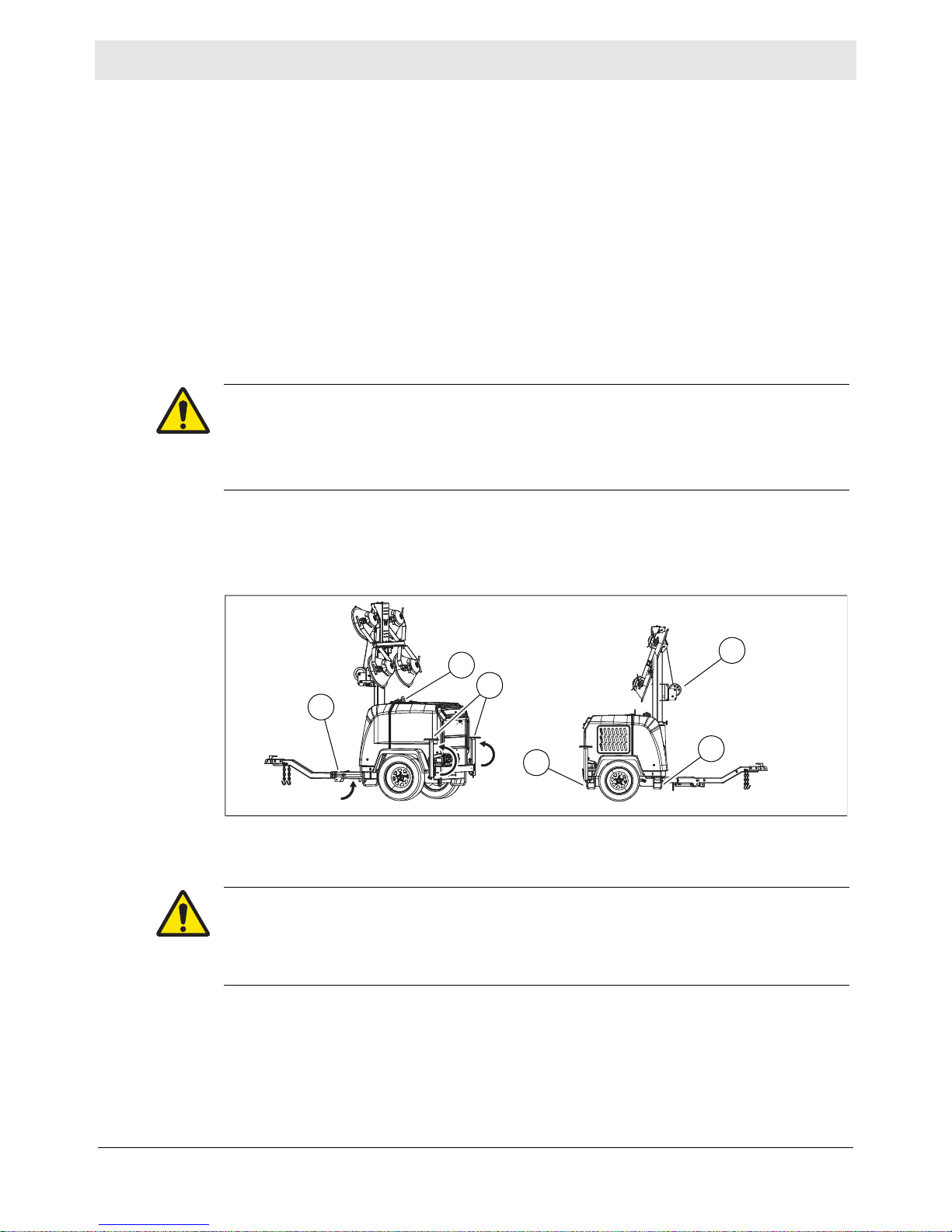
3.1 Lifting the Machine
Requirements
Procedure
■ Properly rated lifting equipment (crane or hoist). See Chapter Technical Data.
■ Machine stopped.
■ All doors and access covers closed and secured.
■ Tower is completely lowered.
■ The winch (e) and lights are facing foward.
■ Outriggers have been returned to their travel position.
■ Outrigger bars and jacks are locked in place.
■ Outrigger jacks (c) are completely cranked in and rotated 180°.
WARNING
Crushing hazard. You may be crushed if the lifting devices fail.
► Never stand under, or get onto, the machine while it is being lifted or moved.
► Use only the designated lifting points to lift the machine.
Perform the procedure below to lift the machine.
1. Attach the lifting equipment to the lifting eye (b) on the machine using hooks,
shackles, and chains or insert forks into the fork pockets (d).
2. Lift the machine a small distance.
WARNING
Crushing hazard. An unstable machine may cause the lifting devices to fail. You
may be crushed if the lifting devices fail.
► Check for stability before continuing.
3. Check for stability. If necessary, lower the machine, reposition the lifting device,
and lift the machine a small distance again.
4. Continue lifting the machine as necessary.
wc_tx004429gb_FM10.fm
30
Page 31

LTV Lifting and Transporting
3.2 Preparing the Machine for Transport on a Truck or Trailer
Requirements
Checklist
■ Machine stopped.
■ Flatbed truck or trailer capable of supporting the machine’s weight.
■ Chains, hooks, or straps capable of supporting the machine’s weight.
WARNING
Crushing hazard. Improperly securing the machine can lead to a crushing hazard.
► Use only the designated tie-down points to secure the machine to a truck or
trailer.
Before transporting the machine, check the following items:
Machine
All doors and access panels of the machine are closed.
All electrical connections are disconnected from the machine.
The generator is shut down.
The tower is completely lowered.
The outriggers are in the travel position.
The outrigger bars and jacks are locked in place.
The tongue jack is in the travel position.
Loading and transporting equipment
The transport vehicle or trailer can support the weight of the machine.
The wheels of the transport vehicle or trailer are chocked during the loading
process.
The transport vehicle or trailer is clean and free of grease, oil, ice, and other
loose material.
Do not use the machine’s trailer jack to support the trailer tongue during
transporting.
Check that any ramps used in the loading process:
■ Can support the weight of the machine
■ Are clean and free of grease, oil, ice, and other loose material.
■ Are securely connected to the transport vehicle or trailer.
■ Are of sufficient length to keep the loading angle 15° or less.
In addition:
The loading area is flat and the ground is stable.
The overall height of the machine once loaded. Plan your travel route so that
there will be adequate clearance for overpasses, road signs, buildings, etc.
Check local regulations regarding transporting and obey these regulations.
wc_tx004429gb_FM10.fm
31
Page 32

Lifting and Transporting LTV
3.3 Before Towing Checklist
For trailer machines only.
Before towing the machine, check the licensing requirements for trailers in your
area. Check the following items:
Machine
All doors and access panels of the machine are closed.
All electrical connections are disconnected from the machine.
The generator is shut down.
The tower is completely lowered.
The outriggers are in the travel position.
The outrigger bars and jacks are locked in place.
The tongue jack is in the travel position.
Hitch and coupler
The towing vehicle and hitch have a rating equal to or greater than the GVWR of
the machine. See Technical Data.
The hitch of the towing vehicle and coupler of the trailer are compatible.
The condition of both the coupler and the hitch.
That all fasteners on the coupler are secure.
That the coupler has fresh grease applied to it.
Wheels
That all lug nuts are in place and are properly torqued.
The tread wear of the tires.
That the tires are inflated to the proper pressure.
Trailer operation
The directional and running lights on the trailer function correctly.
The safety chains of the trailer are connected to the towing vehicle using a
crisscross pattern.
32
wc_tx004429gb_FM10.fm
Page 33

LTV Lifting and Transporting
3.4 Towing the Machine
WARNING
Risk of severe injury or death. Improperly torqued lug nuts can lead to loss of
wheels. Loss of wheels can cause an accident, severe injury or death.
► Tighten the lug nuts to the proper torque before towing the machine.
NOTICE: Wacker Neuson recommends a maximum towing speed of 88 km/h
(55 mph) on highways and paved roads and 16 km/h (10 mph) on rugged roads
and terrain.
Procedure
Perform the procedure below when towing the machine.
1. Read and follow the towing safety guidelines. See topic Safety Guidelines for
Towing the Machine.
2. Complete the shut-down procedures.
3. Adjust the amount of fuel in the machine to approximately 70% capacity to avoid
fuel spillage.
4. Complete the Before Towing Checklist. See topic Before Towing Checklist.
5. Connect the machine to the towing vehicle and connect the lights.
6. Rotate the trailer and tongue jacks to a horizontal position.
7. Tow the machine as needed.
wc_tx004429gb_FM10.fm
33
Page 34

Lifting and Transporting LTV
c
a
a
c
b
b
wc_gr011629
3.5 Trailer
Background
Licensing
requirements
Coupler
maintenance
The machine’s trailer is equipped with safety chains (a), tongue jack (b), lights, and
a coupler (pintle or ball-type) (c).
■ In most states, large trailers must be registered and licensed by the State
Department of Transportation. Before towing, be sure to check licensing
requirements.
■ Drivers towing trailers may be required to carry a commercial driver’s license
(CDL). Check your local and state licensing regulations before towing the
generator.
■ A film of grease on the coupler will extend coupler life and eliminate squeaking.
Wipe the coupler clean and apply fresh grease each time the trailer is towed.
Towing safety
■ When towing, maintain extra space between vehicles and avoid soft shoulders,
curbs and sudden lane changes. If you have not pulled a trailer before, practice
turning, stopping, and backing up in an area away from heavy traffic.
Do not exceed 55 mph when towing a trailer.
34
wc_tx004429gb_FM10.fm
Page 35

LTV Lifting and Transporting
wc_gr014010
d
3.6 Flip-up Tongue
Background
Procedure
The flip-up tongue allows the machine to be stored in a smaller space than a
machine with a conventional tongue.
Perform the procedure below to raise the flip-up tongue to the storage position.
1. Remove the pin behind the tongue jack (a).
b
a
c
Towing
wc_gr014009
2. Rotate the tongue into the storage position (b) and insert the pin (c).
3. Install cotters (d) in all the pins.
Reverse the procedure when preparing the tongue for towing.
wc_tx004429gb_FM10.fm
35
Page 36

Machine Setup LTV
4
Machine Setup
4.1 Preparing the Machine for First Use
1. Make sure all loose packaging materials have been removed from the machine.
2. Check the machine and its components for damage. If there is visible damage,
do not operate the machine! Contact your Wacker Neuson dealer immediately
for assistance.
3. Take inventory of all items included with the machine and verify that all loose
components and fasteners are accounted for.
4. Attach component parts not already attached.
5. Add fluids as needed and applicable, including fuel, engine oil, and battery acid.
6. Move the machine to its operating location.
36
wc_tx004430gb_FM10.fm
Page 37

LTV Machine Setup
4.2 Positioning the Machine
DANGER
Asphyxiation hazard. Exhaust gas from the machine contains carbon monoxide, a
deadly poison you cannot see or smell. Exposure to carbon monoxide can kill you
in minutes.
► Position the machine so that exhaust will not enter any nearby structures.
WARNING
Fire hazard. Do not move the machine while it is running.
► Shut down the machine before moving or repositioning it.
WARNING
Electric shock hazard. The tower extends up to 7 m (23 ft.) and could contact
overhead wires or obstructions.
► Position the trailer on a firm, flat surface clear of overhead wires and
obstructions.
CO Alarms
Requirements
WARNING
Fire hazard. Machines positioned on a hill or an incline may slide, break away or
roll over.
► Do not position the machine on a hill or an incline.
WARNING
Explosion and fire hazard. Risk of severe injury or death.
► Do not operate the machine near flammable vapors, fuels, or combustibles.
Because this machine produces carbon monoxide (CO), Wacker Neuson
recommends that CO alarms be installed in all structures in close proximity to the
machine. CO alarms provide an extra measure of protection against this poison
that you cannot see or smell.
Install battery-operated CO alarms or plug-in CO alarms with battery backup,
according to the manufacturer’s instructions. CO alarms should be certified to the
requirements of the latest safety standards (UL 2034, IAS 6-96, or CSA 6.19.01).
Test the CO alarm batteries monthly.
Position the machine so that:
■ machine exhaust will not enter nearby structures.
■ the machine does not block traffic.
■ the machine is not near any combustible material or flammable vapor.
■ all of the machine’s access doors/panels may be accessed.
■ the area to be illuminated is at or below the level of the lights.
■ there is room around the machine for the outriggers to be extended.
wc_tx004430gb_FM10.fm
37
Page 38

Machine Setup LTV
4.3 Ground Connection
Location
Function
A ground connection (a) is located on the trailer frame.
a
wc_gr013762
This ground connection is used for electrically grounding the Light Tower when
necessary to comply with the National Electrical Code and other federal, state, and
local regulations. For grounding requirements in your area, consult with a qualified
electrician, electrical inspector, or local agency having jurisdiction over electrical
compliance.
■ If the Light Tower is used at a construction site, there may be additional
regulations which must be observed.
Internal
grounding
■ The exposed, conductive, noncurrent-carrying components that could become
energized (e.g., engine, generator housing, control panel, and trailer) are
bonded (connected to the machine’s frame.
■ The grounding wires of the machine’s power outputs (receptacles) are bonded
(connected) to the machine’s frame.
■ The neutral of the generator stator winding is bonded (connected) to the
machine’s frame.
38
wc_tx004430gb_FM10.fm
Page 39

LTV Machine Setup
4.4 Leveling the Trailer—Vertical Mast Light Towers
WARNING
Tipping and falling hazard. Failure to level the trailer or extend the outriggers will
reduce the stability of the unit.
► Level the trailer and extend the outriggers before raising the tower. The
outriggers must remain extended while the tower is up.
Procedure
Perform the procedure below to level the trailer.
1. Pull the locking pin on the tongue jack (a) and rotate the tongue jack down 90°
as shown. Reinsert the pin once the jack is in position.
b
e
d
c
2. Block or chock the trailer wheels (b).
3. Crank the tongue jack (a) down to raise the trailer tongue off the vehicle.
4. Pull the outrigger lock pins (c) to release the outriggers. Pull both outriggers (d)
out until you feel the lock pin snap into place.
5. Pull the locking pins on the outrigger jacks (e). Rotate the jacks down 180°.
Reinsert the pins once the jacks are in position.
c
d
e
a
wc_gr013324
6. Extend the jack(s) on the highest side(s) of the trailer until they rest firmly on the
ground. Extend the remaining jacks until the trailer is level.
wc_tx004430gb_FM10.fm
39
Page 40

Machine Setup LTV
wc_gr01374
DD
a
50 mm
(2 in)
4.5 Refueling the Machine
Requirements
Procedure
■ Machine shut down
■ Engine cool
■ Machine/fuel tank level with the ground
■ Fresh, clean fuel supply
Perform the procedure below to refuel the machine.
WARNING
Fire hazard. Fuel and its vapors are extremely flammable. Burning fuel can cause
severe burns.
► Keep all sources of ignition away from the machine while refueling.
► Refuel only when the machine is outdoors.
► Clean up spilled fuel immediately.
1. Remove the fuel cap (a).
Result
2. Fill the fuel tank, allowing a minimum of 50 mm (2 in.) expansion space between
the fuel level and the top of the tank.
CAUTION
Fire and health hazard. Fuel expands when heated. Expanding fuel in an ove r-filled
tank can lead to spills and leaks.
► Do not fill the fuel tank completely.
3. Re-install the fuel cap.
The procedure to refuel the machine is now complete.
wc_tx004430gb_FM10.fm
40
Page 41

LTV Machine Setup
wc_gr013746
a
a
a
b
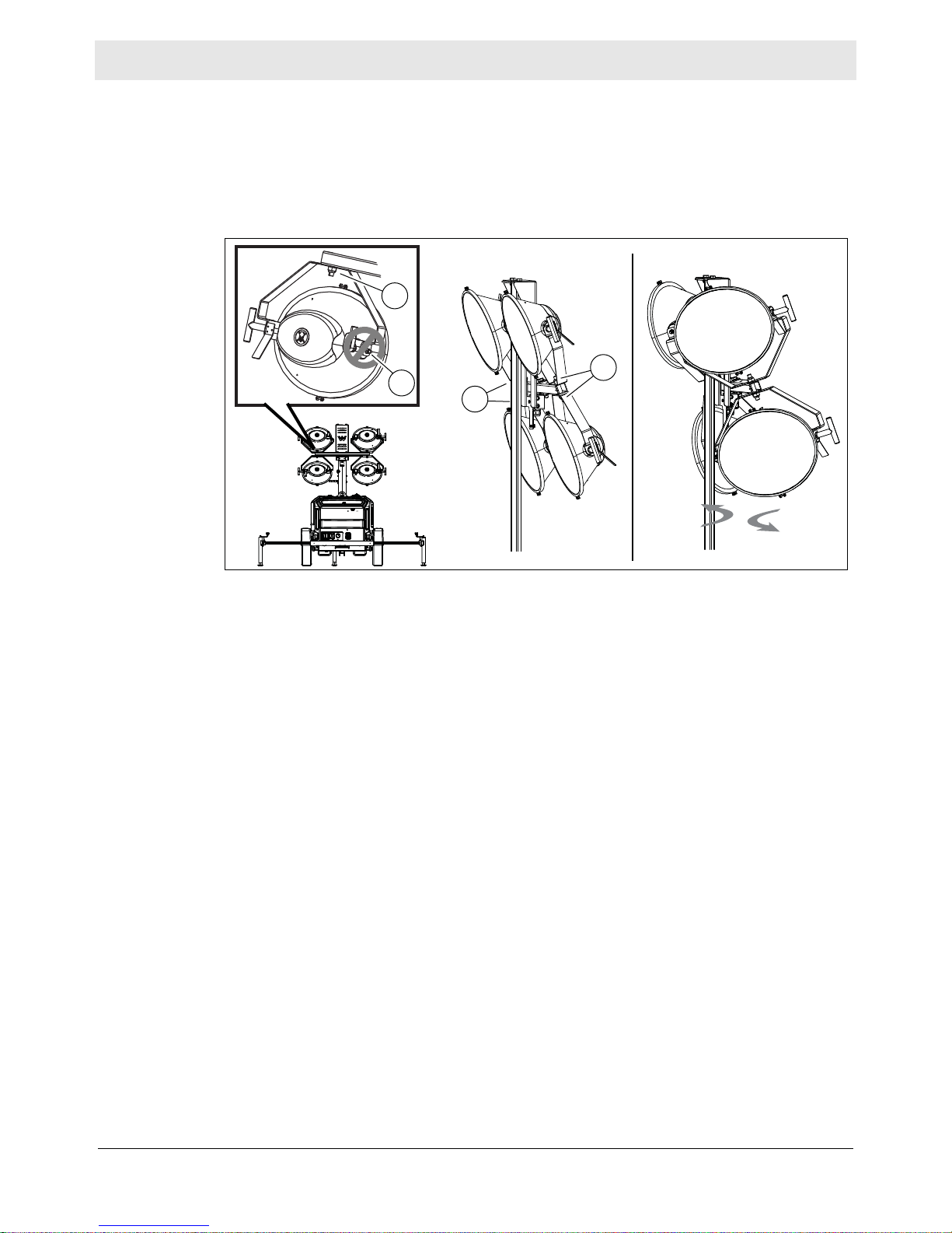
4.6 Aiming the Lights—Vertical Mast Light Towers
Overview
Requirements
Aiming the
light fixtures
■ Each individual light fixture can be independently aimed up, down, left, or right.
There are four total light fixtures on each machine.
■ This procedure is not for rotating the lights as a single unit while the tower is
raised. This procedure requires the tower is lowered and the machine is
stopped. To rotate the lights, see topic Rotating the Lights.
Before adjusting the lights, make sure that the following conditions have been met.
■ Machine is stopped
■ Tower is completely lowered
■ Lights are cool to the touch
Aiming Up or Down
Perform the procedure below to aim an individual light fixture up or down.
1. Loosen the T-handle (a) and aim the light up or down.
NOTICE: Do not loosen the nut (b). Damage to the light fixture may occur.
2. Tighten the T-handle (a) when the light is aimed properly.
3. Repeat steps 1–3 for each remaining light fixture, if desired.
This procedure continues on the next page.
wc_tx004430gb_FM10.fm
41
Page 42
Machine Setup LTV
wc_gr013747
c
c
c
b
Continued from the previous page.
Aiming Left or Right
1. Grasp the light fixture and aim it to the left or right. If necessary, loosen the
bracket nut (c) to allow movement of the fixture.
NOTICE: Do not loosen the nut (b). Damage to the light fixture may occur.
2. If loosened, tighten the bracket nut (c) when the light is aimed properly.
Note: The bracket nut (c) should be only tight enough so that slight resistance is
present when aiming the fixture.
3. Repeat steps 1–2 for each remaining light fixture, if desired.
42
wc_tx004430gb_FM10.fm
Page 43

LTV Machine Setup
wc_gr013767
a
4.7 Manually Rotating the Light Bar
Overview
Procedure
The operator can rotate the light bar 360° while the tower is lowered.
Perform the procedure below to rotate the light bar.
1. Loosen out the locking knob (a).
2. Rotate the light bar to the desired position.
3. Tighten the locking pin (a).
Note: Before towing, aim the light bar forward. Be sure the locking pin seats into a
hole in the light bar. Holes are positioned at 90° angles.
wc_tx004430gb_FM10.fm
43
Page 44

Machine Setup LTV
4.8 Raising the Tower—Manual Winch System
Background
Requirements
The Light Tower includes a telescoping winch for raising the towe r. The winch is an
automatic brake-type winch that automatically brakes when the handle is released.
The handle must be rotated to wind in the cable as well as to unwind the cable.
■ Engine is stopped
■ Light Tower is located on a firm, flat surface clear of overhead wires and
obstructions
■ Winch cables are in serviceable condition and resting properly in pulleys
■ Light tower has been leveled, with all outriggers extended and locked
WARNING
Electric shock hazard! Do not use the Light Tower if insulation on any of the
electrical cords is cut or worn through. Bare wires in contact with the metal frame of
the trailer or tower can cause electrocution.
► Repair or replace the cord before using the machine.
WARNING
Electrocution hazard.
► Do not position the Light Tower under electrical power lines.
WARNING
Tipping/falling hazards. Certain actions may cause the tower to fall or the Light
Tower to tip over.
► Do not raise the tower or operate the Light Tower in high winds.
► Do not touch the winch pawl while the tower is raised!
► Do not pull the vertical tower locking pin while the tower is raised.
WARNING
Personal injury hazard. Bystanders can be struck by the tower as it is being raised
or lowered.
► Do not allow anyone to stand near the front of the machine while raising or
lowering the tower.
This procedure continues on the next page.
44
wc_tx004430gb_FM10.fm
Page 45

LTV Machine Setup
wc_gr013770
a
Continued from the previous page.
Reference
graphic
Procedure
NOTICES
Raising the
tower
Perform the procedure below to raise the tower.
■ Do not attempt to raise the tower if the winch is damaged or not operating
properly, or if the winch cables are worn or damaged.
■ The tower and light bar can be rotated 360°. If you wish to position the light bar
so the lights illuminate to the left, to the right, or to the rear, the light bar should
be rotated when the tower is fully lowered. See topic Manually Rotating the Light
Bar.
1. Check the operation of the telescoping winch (a) by rotating its handle 1/4 turn
clockwise (“cable in” direction). The winch pawl must engage the winch gear
teeth. When operating properly, the winch pawl will make a “clicking” sound
when its handle is rotated clockwise.
2. Continue rotating the winch handle until the tower is at the desired height. Do
not overcrank the winch when the tower is fully extended.
wc_tx004430gb_FM10.fm
45
Page 46

Machine Setup LTV
4.9 Lowering the Tower—Manual Winch System
Requirements
Procedure
■ Lights are turned off
■ Engine is stopped
■ Outriggers are extended and locked in place
WARNING
Tipping/falling hazards. Certain actions may cause the tower to fall or the machine
to tip over.
► Do not raise the tower or operate the Light Tower in high winds.
► Do not touch the winch pawl while the tower is raised!
Perform the procedure below to lower the tower.
WARNING
Personal injury hazard. Bystanders can be struck by the tower as it is being raised
or lowered.
► Do not allow anyone to stand near the front of the machine while raising or
lowering the tower.
1. Turn the handle on the telescoping winch (a) counterclockwise (“cable out”
direction) until the tower is lowered completely.
a
b
This procedure continues on the next page.
wc_gr013771
wc_tx004430gb_FM10.fm
46
Page 47

LTV Machine Setup
Continued from the previous page.
2. If the light bar has been rotated, loosen the locking knob (b) and rotate the tower
so the light bar and winch are facing toward the trailer tongue. See topic
Manually Rotating the Light Bar.
3. If the lights have been aimed vertically or horizontally, return them to a position
parallel to the light bar . See topic Aiming the Ligh ts—Vertical Mast Light Towers.
wc_tx004430gb_FM10.fm
47
Page 48

Machine Setup LTV
4.10 Raising the Tower—Power Winch System
Background
Requirements
The Light Tower includes a telescoping winch for raising the tower.
■ Machine is shut down
■ Light Tower is located on a firm, flat surface clear of overhead wires and
obstructions
■ Winch cables are in serviceable condition and resting properly in pulleys
■ Light Tower has been leveled, with all outriggers extended and locked
WARNING
Electric shock hazard! Do not use the machine if insulation on any of the electrical
cords is cut or worn through. Bare wires in contact with the metal frame of the trailer
or tower can cause electrocution.
► Repair or replace the cord before using the machine.
WARNING
Electrocution hazard.
► Do not position the Light Tower under electrical power lines.
WARNING
Tipping/falling hazards. Certain actions may cause the tower to fall or the machine
to tip over.
► Do not raise the tower or operate the Light Tower in high winds.
► Do not pull the vertical tower locking pin while the tower is raised.
WARNING
Personal injury hazard. Bystanders can be struck by the tower as it is being raised.
► Do not allow anyone to stand near the front of the machine while raising the
tower.
This procedure continues on the next page.
wc_tx004430gb_FM10.fm
48
Page 49

LTV Machine Setup
Continued from the previous page.
Procedure
NOTICES
Raising the
tower
Perform the procedure below to raise the tower.
■ Do not attempt to raise the tower if the winch is damaged or not operating
properly, or if the winch cables are worn or damaged.
■ The tower and light bar can be rotated 360°. If you wish to position the light bar
so the lights illuminate to the left, to the right, or to the rear, the light bar should
be rotated when the tower is fully lowered. See topic Manually Rotating the Light
Bar.
1. Check the operation of the telescoping winch (a). Turn the telescope rotary
switch (b) on the control panel to the up position.
b
a
2. Continue to hold the telescope rotary switch until the tower is at the desired
height. Release the switch when the tower is at the desired height.
wc_tx004430gb_FM10.fm
wc_gr013772
49
Page 50

Machine Setup LTV
wc_gr013773
a
b
4.11 Lowering the Tower—Power Winch System
Requirements
Procedure
■ Lights are turned off
■ Engine is stopped
■ Outriggers are extended and locked in place
WARNING
Tipping/falling hazards. Certain actions may cause the tower to fall or the machine
to tip over.
Perform the procedure below to lower the tower.
WARNING
Personal injury hazard. Bystanders can be struck by the tower as it is being raised
or lowered.
► Do not allow anyone to stand near the front of the machine while raising or
lowering the tower.
1. Hold the rotary switch (b) in the down position (“cable out” direction) until the
tower is completely lowered.
This procedure continues on the next page.
wc_tx004430gb_FM10.fm
50
Page 51

LTV Machine Setup
Continued from the previous page.
2. If the light bar has been rotated, loosen the locking knob (a) and rotate the tower
so the light bar and winch are facing toward the trailer tongue. See topic
Manually Rotating the Light Bar.
3. If the lights have been aimed vertically or horizontally, return them to a position
parallel to the light bar . See topic Aiming the Ligh ts—Vertical Mast Light Towers.
wc_tx004430gb_FM10.fm
51
Page 52

Operation LTV
5 Operation
5.1 Generator Derating
Description
Derating
percentage s
All generator sets are subject to derating (reduced power output) depending on the
altitude and ambient temperature. Derating should not affect the operation of the
floodlights, although it will reduce the available reserve power to the receptacle.
Power ratings are typically reduced by the following percentages:
■ 3% per 300 m (1000 ft.) elevation above sea level
■ 2% per 5.5°C (10°F) increase in ambient temperature above 25°C (78°F).
52
wc_tx004431gb_FM10.fm
Page 53

LTV Operation
wc_gr013749
a
b d
c
a
b
c
e
f
6K 8K
6K
g
h
j
k
m m
n
8K
n
p
5.2 Control Panels and Receptacles—KUBOTA
Ref. Description Ref. Description
a 33A main circuit breaker (8K)
50A main circuit breaker (6K)
b 33A GFI circuit breaker (8K)
25A GFI circuit breaker (6K)
c 30A lights circuit breaker k 30A receptacle breaker
d Tower winch rotary switch (optional) m 20A GFI receptacle
e Key switch n 30A receptacle
f Glow plug indicator p Shower power inlet
g Hour meter
h Shore power switch
(optional for 6K)
j Control panel light
(standard for 8K)
(optional for 6K)
wc_tx004431gb_FM10.fm
53
Page 54

Operation LTV
wc_gr013750
h
g
f
e
dcba
j m
k
n
o
p q
r s
t
u
v
5.3 Control Panels and Receptacles—KOHLER
Ref. Description Ref. Description
a Low fuel indicator (not used) m Tower winch rotary switch (optional)
b Safety shut-down indicator n 20A GFI circuit breakers (optional)
c Low oil pressure shut-down
indicator
d High coolant temperatur e shut-
down indicator
e Alternator indicator q Key switch
f Auxiliary lights (not used) r Hour meter
g Glow plug indicator s Control panel light
h 50A main circuit breaker t 20A GFI receptacle
j 20A GFI circuit breaker u 30A receptacle (optional)
k 30A lights circuit breaker v Shore power inlet (optional)
o Air filter restriction indicator
p Auxiliary lights (not used)
54
wc_tx004431gb_FM10.fm
Page 55

LTV Operation
wc_gr013748
c
b
a
d
f
e c
d
e
g
h
j
6K 8K
6K
k
m
n
o
p
o
p
8K
5.4 Control Panel and Receptacles—DeepSea
Ref. Description Ref. Description
a Menu navigation buttons (up/down) h Auto start button
b Controller display j Start button
c 25A main circuit breaker (6K)
33A main circuit breaker (8K)
d 20A GFI circuit breaker m Control panel light
e 30A lights circuit breaker n 30A receptacle breaker
f Tower winch rotary switch (optional) o 20A GFI receptacle
g St op/reset button p 30A receptacle
k Hour meter
(standard for 8K)
wc_tx004431gb_FM10.fm
55
Page 56

Operation LTV
wc_gr012363
wc_gr012362
wc_gr012361
wc_gr012364
wc_gr012356
5.5 Machine Monitoring – DeepSea
Description
Engine and generator information is displayed on the the LCD panel The user can
scroll through the screens to monitor machine parameters.
V olt s “V”- Displays the AC outpu t volt age being produced by the
generator.
V olt s “V”- Displays the AC outpu t volt age being produced by the
generator.
Hertz “Hz” - Displays output frequency. This gauge should read
approximately 60 Hz under a no-load condition. If the frequency
is too high, check the engine rpm.
Displays the engine rpm.
Displays the metered usage of the machine in hours (h) and
minutes (m).
wc_tx004431gb_FM10.fm
56
Page 57

LTV Operation
Displays the available voltage of the battery.
wc_gr012357
Displays the maintenance interval as well as the time remaining
until maintenance is required.
Each parameter is displayed on a separa te screen:
■ Oil change
■ Air filter
■ Fuel filter
wc_gr012360
wc_tx004431gb_FM10.fm
57
Page 58

Operation LTV
wc_gr012354
a
b
c
d
e
wc_gr012355
f
g
h
j
i
k
n
l
5.6 Alarms and Shut-Down Conditions – DeepSea
Background
Warning
alarms
The Light Tower controller monitors variables of engine and machine function. The
Light Tower controller has two types of alarms: warning alarms and shut-down
alarms.
Warnings are non-critical alarm
conditions that do not affect the operation
of the generator system. They serve to
draw the operator’s attention to an
undesirable condition. Warning alarms
are self-resetting when the fault condition
is removed.
Warning alarms include:
a.Generator over-frequency
b.Generator under-frequency
c.Time to maintenance-oil
d.Time to maintenance-air filter
e.Time to maintenance-fuel filter
During a warning alarm condition, the
LCD panel displays the type of warning
alarm. The machine is not shut down.
Shut-down
alarms
Shut-down alarms are latching alarms
and stop the generator. Shut-down
alarms include:
f. High coolant temperature
g.Low oil pressure
h.Overspeed
i. Underspeed
j. Generator over-frequency
k.Generator under-frequency
l. Overcrank
m.Low coolant level (if equipped)
n.Emergency stop
During a shut-down alarm condition, the
LCD panel displays the type of alarm that
caused the machine shutdown. Remove
the fault condition, then press “Stop”.
This procedure continues on the next page.
58
wc_tx004431gb_FM10.fm
Page 59
LTV Operation
Continued from the previous page.
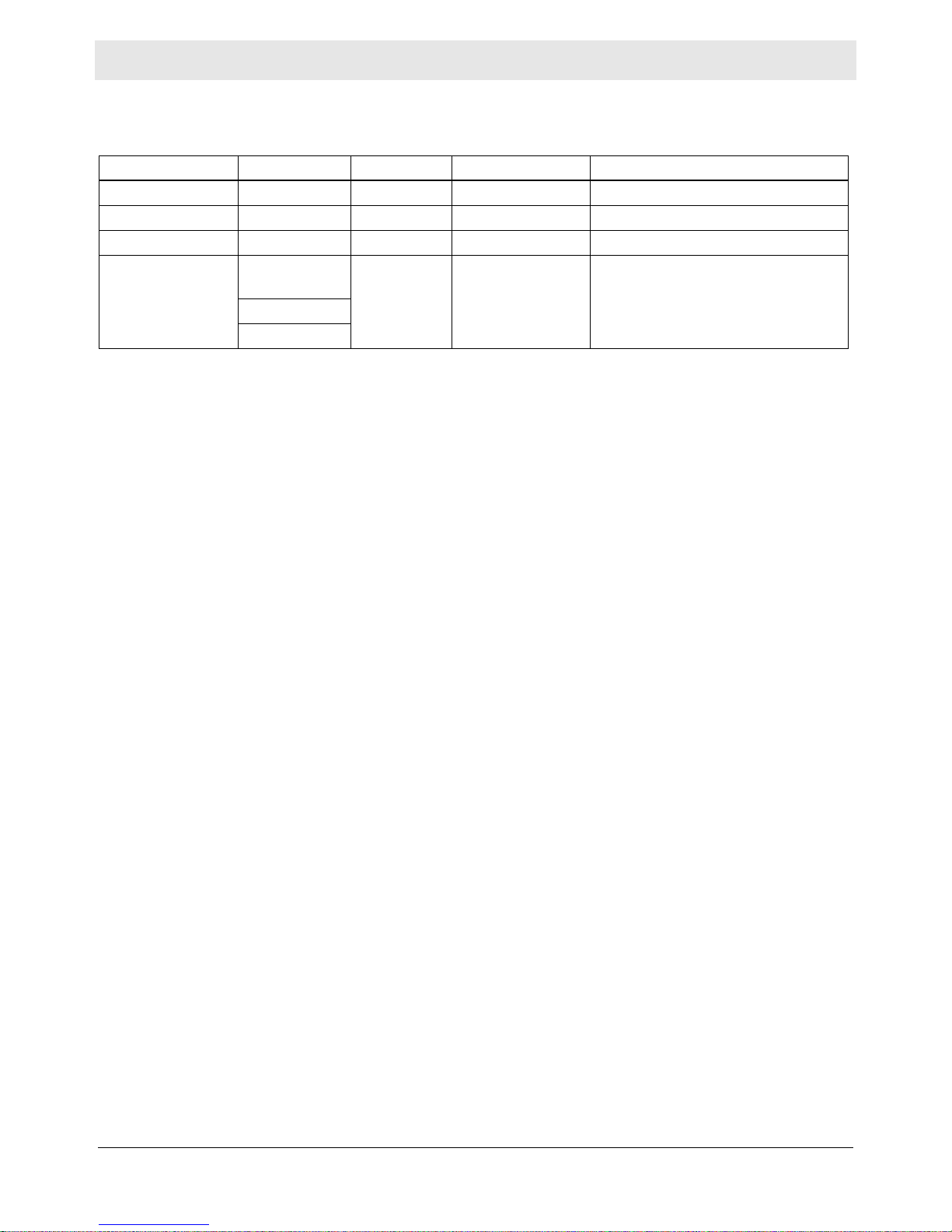
Alarm and Shutdown limits
Variable Normal Warning Shutdown To Reset
Overspeed 60 Hz 63 Hz 66 Hz Press “Stop”.
Underspeed 60 Hz 57 Hz 55 Hz Press “Stop”.
Overcrank — — After 3 attempts Press “Stop”.
Time to maintain:
■ Oil
■ Air
■ Fuel
750 hours
250 hours
500 hours
0 hours —
Navigate to the applicable
maintenance screen and press and
hold “Stop” for 10 seconds.
wc_tx004431gb_FM10.fm
59
Page 60
Operation LTV
b
a
wc_gr012367
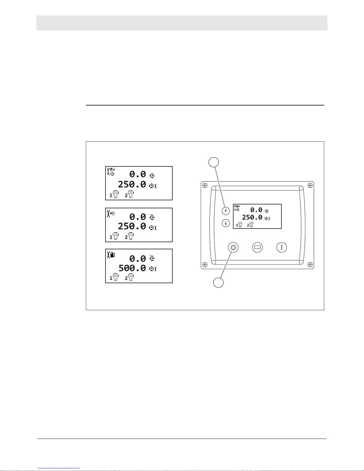
5.7 Resetting the Maintenance Timers – DeepSea
Background
Procedure
The maintenance timers are preset on the controller. When the timer expires, the
alarm will display in the upper right corner of the screen. The maintenance timers
are preset as follows:
■ Oil change interval: 750 hours
■ Air filter change interval: 250 hours
■ Fuel filter change interval: 500 hours
After the required maintenance has been completed, perform the following
procedure to reset a maintenance timer.
1. Use the up and down arrows (a) to navigate to the applicable screen.
2. Press and hold the “Stop” button (b) for 10 seconds. The timer will reset.
wc_tx004431gb_FM10.fm
60
Page 61

LTV Operation
5.8 Before Starting
Before putting the Light Tower into service, review each item on the following
checklist. Light Towers often run unattended for long periods of time. Therefore, it
is important to make sure that the machine is set up properly to avoid possible
operating problems.
CAUTION
Improper machine setup may cause injury or equipment damage.
► Perform all pre-start checks listed below. Do not operate the machine until all
items on the checklist have been addressed.
Check
machine
condition
Check the
engine
Review safety
information
Verify that the machine is level and positioned on a stable surface.
Perform a walk-around to check for visible damage.
Inspect the lights and lamps: ensure that glass is not broken or cracked.
Ensure that all electrical connections are tight.
Verify that all electrical cords a re in serviceable condition with no exposed wires,
cuts, or cracks in the insulation.
Close and secure access covers before starting the machine.
Check fuel, engine oil, and coolant levels. Add fluids if necessary.
Verify that the air filter element is clean and undamaged. Replace if necessary.
Check to make sure no debris has lodged in vents, near the radiator, or around
the fan.
Check to make sure that the exhaust compartment is clean and nothing is
touching the muffler or exhaust pipes.
Check fan belt and hoses on engine for loose connections or fraying. Tighten or
replace as required.
Review and follow instructions provided in the “Safety Information” chapter at
the beginning of this Operator’s Manual.
wc_tx004431gb_FM10.fm
61
Page 62

Operation LTV
wc_gr013751
a
b d
c
e
g
f
8K
5.9 Starting, Operating, Stopping the Machine—KUBOTA
Requirements
NOTICES
■ Before starting checks completed. See topic Before Starting.
■ Electrical cables in good condition with no cuts or abrasions in the insulation.
■ Circuit breakers (a, b, c, and d, g for 8K) are in the OFF position.
■ All loads are disconnected from the machine.
■ Do not use evaporative starting fluids (for example, ether) to start the engine.
■ Do not start the engine under load.
Starting the
machine
Perform the procedure below to start the machine.
1. Rotate the key (e) counterclockwise to the “HEAT” position.
■ The glow plug indicator (f) will illuminate.
■ The glow plug indicator will turn off when the engine is preheated.
NOTICE: Cranking the engine longer than 20 seconds could cau se damage. If the
engine does not start, return the key to the “OFF” position and wait 1 minute for the
starter to cool before proceeding.
2. Immediately rotate and hold the key (e) to the “START” position until the engine
starts, then release the key.
3. Allow the engine to warm up before operating the lights.
Note: If the oil does not reach operating pressure within 30 seconds, the engine
will stop. You must return the key to the OFF position for 30 seconds before
attempting to restart the engine.
This procedure continues on the next page.
wc_tx004431gb_FM10.fm
62
Page 63

LTV Operation
wc_gr013751
a
b d
c
e
g
f
8K
Continued from the previous page.
Operating the
lights
Notes
Perform the procedure below to operate the lights.
1. Turn on the main circuit breaker (a).
2. Turn on individual circuit breakers (c) one at a time.
■ Metal halide floodlights require a warm-up time of 5–15 minutes before they
reach full brightness.
■ After turning the lights off, a cool-down time of 10 minutes is necessary before
they can be turned on again.
Stopping the
machine
NOTICE: Turn off the lights before stopping the engine. Failure to do so will
damage the electrical system.
Perform the procedure below to stop the machine.
1. Disconnect all loads from the machine.
2. Turn the circuit breakers (a) off.
3. Rotate the key (e) to the OFF position.
wc_tx004431gb_FM10.fm
63
Page 64

Operation LTV
wc_gr013753
a
b
c
f
e
5.10 Starting, Operating, and Stopping the Machine—KOHLER
Requirements
NOTICES
Check the following items before starting the machine.
■ Before starting checks completed. See topic Before Starting.
■ Electrical cables are in good condition with no cuts or abrasions in the
insulation.
■ Circuit breakers (a, b, c) are in the “OFF” position.
■ All loads are disconnected from the machine.
■ Do not use evaporative starting fluids (e.g., ether) to start the engine.
■ Do not start the engine under load.
■ If the fuel tank was empty, you may need to bleed the fuel lines. Refer to the
engine manufacturer’s documentation.
Starting the
machine
Perform the procedure below to start the machine.
1. Rotate the starting key (e) one click to the right.
■ The glow plug indicator (f) will illuminate.
■ The glow plug indicator will turn off when the engine is preheated.
2. Immediately rotate and hold the starting key (e) to the “START” position until the
engine starts, then release the key.
NOTICE: Cranking the engine longer than 20 seconds can cause damage. If the
engine does not start, return the starting key to the “OFF” position and wait 1
minute for the starter motor to cool before proceeding.
3. Allow the engine to warm up before operating the lights.
Note: If the oil does not reach operating pressure within 30 seconds, the engine
will stop. You must return the starting key to the “OFF” position for 30 seconds
before restarting the engine.
This procedure continues on the next page.
wc_tx004431gb_FM10.fm
64
Page 65

LTV Operation
wc_gr013753
a
b
c
f
e
Continued from the previous page.
Operating the
lights
Notes
Perform the procedure below to operate the lights.
1. Turn on the main circuit breaker (a).
2. Turn on individual circuit breakers (c) one at a time.
■ Metal halide floodlights require a warm-up time of 5–15 minutes before they
reach full brightness.
■ After turning the lights off, a cool-down time of 10 minutes is necessary before
they can be turned on again.
Stopping the
machine
NOTICE: Turn off the lights before stopping the machine. Failure to do so may
damage the generator.
Perform the procedure below to stop the machine.
1. Remove all connected loads from the machine.
2. Turn the circuit breakers (a, b, c) off.
3. Rotate the starting key (e) to the “OFF” position.
wc_tx004431gb_FM10.fm
65
Page 66

Operation LTV
wc_gr013779
a
b d
c
g
h
f
e
8K
5.11 Starting, Operating, Stopping the Machine—DeepSea
Prerequisites
NOTICES
■ Before starting checks completed. See topic Before Starting.
■ Electrical cables in good condition with no cuts or abrasions in the insulation.
■ Circuit breakers (a, b, c and d, h for 8K) are in the OFF position.
■ All loads are disconnected from the machine.
■ Do not use evaporative starting fluids (for example, ether) to start the engine.
■ Do not start the engine under load.
Procedure
Follow the procedure below to manually start the machine.
1. Press the START switch (f). This initiates the pre-heat timer, energizes the fuel
solenoid, and energizes the starter motor.
2. The engine will crank for 10 seconds, and then rest for 10 seconds. If the engine
does not start immediately, the cycle will repeat three (3) times.
3. If the engine does not start after three attempts, the starting sequence will be
terminated and the Overcrank shutdown indicator (g) will light.
4. When the engine starts, the starter motor is disengaged.
Note: After the starter motor has disengaged, the Safety On Timer is activated.
This timer is pre-set for a 12 second delay and allows oil pressure, high engine
temperature, underspeed, and charge failure to stabilize without triggering the
fault.
5. If a fault occurs after the 12-second delay, see section Meanings of Genset
Controller Indicator Lights.
6. Allow engine to warm up before operating lights.
This procedure continues on the next page.
66
wc_tx004431gb_FM10.fm
Page 67
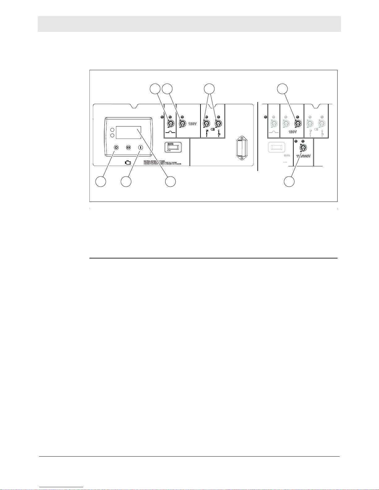
LTV Operation
wc_gr013779
a
b d
c
g
h
f
e
8K
Continued from the previous page.
Operating the
lights
Notes
Perform the procedure below to operate the lights.
1. Turn on the main circuit breaker (a).
2. Turn on individual circuit breakers (c) one at a time.
■ Metal halide floodlights require a warm-up time of 5–15 minutes before they
reach full brightness.
■ After turning the lights off, a cool-down time of 10 minutes is necessary before
they can be turned on again.
Stopping the
machine
NOTICE: Turn off the lights before stopping the engine. Failure to do so will
damage the electrical system.
Perform the procedure below to stop the machine.
1. Disconnect all loads from the machine.
2. Turn the circuit breakers (a) off.
3. Push the STOP button (e) to de-energize the fuel solenoid.
wc_tx004431gb_FM10.fm
67
Page 68

Operation LTV
a
b
c
d
e
wc_gr014008
5.12 Auto Mode (Remote Run)
The engine controller is capable of automatically starting the engine.
A scheduled run will begin only if the controller is in Auto Mode with no shut-down
alarm present. If the controller is in Stop/Reset Mode or Manual/Start Mode when a
scheduled run begins, the engine will not start. However, if the controller is set to
Auto Mode during a scheduled run, the engine will start.
A system designer can configure an external input to prevent a scheduled run.
If the engine is running “Off Load” in Auto Mode and a scheduled run configured to
“On Load” begins, the set is placed “On Load” for the duration of the schedule.
Front Panel
Configuration
This configuration mode allows the operator to fully configure the module through
its display without the use of the computer software.
Use the controller’s buttons to navigate through the menu and change the
parameters.
■ Next section (a)
■ Previous section (b)
■ Previous parameter (c)
■ Edit or save parameter (d)
■ Next parameter (e)
Editing a
Parameter
Note: Use the computer software for more comprehensive module configuration.
Note: If a PIN code is required, contact the generator supplier for the PIN code. If
the PIN code is lost or forgotten, return the controller to the Deep Sea factory to
remove the code. For security purposes, the PIN code automatically resets when
the editor is exited (manually or automatically).
1. To enter the editor mode, press the “Stop” (c) and “Auto” (d) buttons
simultaneously.
2. Press the up (a) and down (b) arrows to select the Configuration Editor or
Operator Editor. The selected editor flashes.
68
wc_tx004431gb_FM10.fm
Page 69

LTV Operation
3. Press “Auto” to enter the selected editor.
Note: If a PIN code has been set for the Configuration Editor, the PIN request
appears.
4. Press the up and down arrows to adjust first digit to the correct value.
5. Press the “Start” button (e) when the first digit is correctly entered. The digit
changes to # for security purposes.
6. Enter each of the digits of the PIN number. Press “Stop” to move back to adjust
one of the previous digits.
7. After entering the last digit, press “Auto” to validate the PIN code. If the number
is not correct, the editor is exited.
Note: Press and hold “Stop” or “Start” to enable the auto-repeat functionality.
8. Once in the selected editor, press the up and down arrows to cycle thro ugh it in
increments of 100. Press “Stop” or “Start” to cycle through the editor in
increments of 1. The table below lists the parameters needed to configure a
schedule.
9. To select a parameter to edit, press “Auto.” The parameter value flashes.
10.Press “Stop” or “Start” to adjust the value to the required setting.
11.Press “Auto” the save the current value. The value stops flashing.
Note: For security purposes, the editor automatically exits after 5 minutes of
inactivity.
12.To save and exit the editor, press and hold “Auto.” To exit without saving, press
and hold “Stop.”
Configuration Parameters – Scheduler
901 Enable Scheduler On (1), Off (0)
902 Schedule Run On or Off Load On (1), Off (0)
903 Schedule Period Weekly (0), Monthly (1)
904 Scheduler (1) Start Time 0:00:00
905 Scheduler (1) Start Day 0 (1=Monday)
906 Scheduler (1) Start Week 1,2,3,4
907 Scheduler (1) Duration 0:00:00
908 Scheduler (2) Start Time 0:00:00
909 Scheduler (2) Start Day 0 (1=Monday)
910 Scheduler (2) Start Week 1,2,3,4
911 Scheduler (2) Duration 0:00:00
912 Scheduler (3) Start Time 0:00:00
913 Scheduler (3) Start Day 0 (1=Monday)
914 Scheduler (3) Start Week 1,2,3,4
wc_tx004431gb_FM10.fm
69
Page 70

Operation LTV
915 Scheduler (3) Duration 0:00:00
916 Scheduler (4) Start Time 0:00:00
917 Scheduler (4) Start Day 0 (1=Monday)
918 Scheduler (4) Start Week 1,2,3,4
919 Scheduler (4) Duration 0:00:00
920 Scheduler (5) Start Time 0:00:00
921 Scheduler (5) Start Day 0 (1=Monday)
922 Scheduler (5) Start Week 1,2,3,4
923 Scheduler (5) Duration 0:00:00
924 Scheduler (6) Start Time 0:00:00
925 Scheduler (6) Start Day 0 (1=Monday)
926 Scheduler (6) Start Week 1,2,3,4
927 Scheduler (6) Duration 0:00:00
928 Scheduler (7) Start Time 0:00:00
929 Scheduler (7) Start Day 0 (1=Monday)
930 Scheduler (7) Start Week 1,2,3,4
931 Scheduler (7) Duration 0:00:00
932 Scheduler (8) Start Time 0:00:00
933 Scheduler (8) Start Day 0 (1=Monday)
934 Scheduler (8) Start Week 1,2,3,4
935 Scheduler (8) Duration 0:00:00
5.13 Engine - Jump-Starting
Background
Jump-starting may occasionally be required if a battery is discharged. If jumpstarting is necessary, the following procedure is recommended to prevent starter
damage, battery damage, and personal injuries.
WARNING
Personal injury hazard.
Jump-starting a battery incorrectly can cause the battery to explode, resulting
in severe personal injury
Keep all arcs, sparks, flames, and lighted tobacco away from the battery.
►
► Do not jump-start a frozen battery.
► Do not short circuit battery posts. Do not touch the frame or the negative
terminal when working on the positive terminal.
► Wear safety glasses and gloves while using cables.
or death.
70
wc_tx004431gb_FM10.fm
Page 71

LTV Operation
WARNING
Battery fluid is poisonous and corrosive.
► In the event of ingestion or contact with skin or eyes, seek medical attention
immediately.
NOTICE:
Observe the following precautions to prevent serious damage to the electrical
system.
Jump-starting a shorted or defective battery will cause the voltage regulator to
supply higher than normal voltage. This can severely damage the digital
electronics that control machine operation. If there is any doubt as to the battery’s
condition, a replacement battery should be used or an attempt should be made to
charge the battery before starting the machine.
Do not connect the negative clamp to a carburetor, fuel lines, or sheet metal body
parts.
Do not attempt to operate the machine without a battery.
Procedure
Dispose of waste batteries in accordance with local environmental regulations.
CAUTION
Electrical arcing can cause severe personal injury.
► Do not allow positive and negative cable ends to touch.
Perform the procedure below to jump-start the battery.
1. In very cold weather, check the condition of the electrolytes. If it seems slushy or
frozen, do not try jump-starting until it thaws.
NOTICE:
If a battery sits in extreme cold, the electrolytes inside the battery can freeze.
Attempting to jump-start a frozen battery can cause it to rupture.
2. Disconnect engine load.
3. Use a booster battery of the same voltage as is used with your engine system.
4. Attach one end of the positive cable clamp (red) to the positive (+) terminal of
the dead battery. Attach the other end of the positive cable clamp to the positive
terminal of the booster battery.
5.
Attach the negative cable clamp (black) to the negative (-) terminal of the
booster battery. Attach the other end of negative cable clamp to a solid chassis
ground on your engine or unpaired portion of the machine frame away from the
"discharged" battery.
wc_tx004431gb_FM10.fm
71
Page 72

Operation LTV
6. Start the engine on the machine that is being used as a power source.
7. Wait for a minimum of two minutes while the battery in the stalled machine
partially charges.
8. Turn the engine key switch and hold it until the engine starts.
NOTICE:
Cranking the engine for more than five seconds can cause starter damage. If the
engine fails to start, release the key switch and wait 10 seconds before operating
the starter again. If the engine still fails to start see Troubleshooting.
9. Immediately after the stalled engine starts, disconnect the negative cable clamp
first from the previously dead battery and then the negative cable clamp of the
booster battery.
10.Disconnect the positive cable clamp from the booster battery and then the
positive cable clamp from the previously dead battery.
11.When using light or high amperage draw accessories, idle the engine for a
period of 20 minutes to bring the battery to charge state.
Result
The machine has now been jump-started.
72
wc_tx004431gb_FM10.fm
Page 73

LTV Operation
5.14 Emergency Shutdown Procedure
General
procedures
Perform the procedure below if a breakdown or accident occurs while the machine
is operating:
1. Stop the engine.
2. Disconnect all loads from the machine.
3. Lower the tower.
4. Allow the machine to cool before opening the cabinet.
5. Contact the rental yard or machine owner for further instructions.
WARNING
Personal injury hazard. Raising or lowering the tower creates situations that if not
avoided, will cause death or serious injury from striking, crushing, pinching,
electrocution, etc.
► Keep the area under and around the lights clear of people and obstructions
while raising and lowering the tower.
wc_tx004431gb_FM10.fm
73
Page 74

Operation LTV
wc_gr013768
b b
a
8K
5.15 Using the Convenience Receptacles—60 Hz
Description
Mandates
This machine is equipped with one or more convenience receptacles (a) for
running accessories and tools from the generator. Each receptacle is protected by
its own circuit breaker (b). Power to the receptacle(s) is available any time the
engine is running and the circuit breaker is set to the ON position.
Obey the mandates below to avoid damaging the machine, accessories, or tools.
■ Do not use frayed or damaged cords or plugs with the convenience receptacle.
■ For machines with metal halide lights, the maximum watt age (with t he light s on)
drawn from the receptacles shall not exceed the values below.
■ LTV6: 1660W
■ LTV8: 3660W
■ Use only tough rubber-sheathed flexible cable or equivalent. (per 1EC245-4).
■ When using extension cords or mobile distribution networks, the total length of
cords should not exceed the values below.
■ 16 gauge: 60 m (197 ft.)
■ 13 gauge: 100 m (328 ft.)
■ Machines with metal halide lights generate increased voltage while the light s are
reaching full brightness. To avoid damaging sensitive electronic equipment, do
not connect any such devices to the convenience outlet until the machine and
lights have been operating for at least ten minutes.
■ Each 120V GFI receptacle (a) is protected by a 20A circuit breaker (b).
Testing a GFI
receptacle
Perform the procedure below before each use to test a GFI receptacle.
1. Push the test button in.
■ The reset button should pop out.
■ Power to the receptacle is now off.
2. Push the reset button in.
NOTICE: If the reset button does not pop out, the GFI is defective. Do not use the
receptacle until the problem is corrected.
wc_tx004431gb_FM10.fm
74
Page 75

LTV Factory-Installed Options
wc_gr014011
a
wc_gr014012
b
6 Factory-Installed Options
This machine may be equipped with one or more of the following factory-installed
options. To verify if any of these options are installed on your machine, contact
Wacker Neuson Corporation at 1-800-770-0957. A nameplate listing the Model
Number, Item Number, Revision, and Serial Number is attached to each unit.
Please have this information available when contacting Wacker Neuson
Corporation.
The illustrations shown in this chapter represent typical installations. The factoryinstalled options on your machine may look different.
6.1 Cold Weather Package
The cold weather package includes the engine block heater, battery blanket, oil
pan heater, and 60/40 or cold weather coolant. The Kohler cold weather package
also includes the piston fuel pump.
6.2 Engine Block Heater
The Kohler (a) and Kubota (b) engine block heaters include a block heater with a
cord. The function of the block heater is to heat the engine coolant/engine block to
improve cold-weather engine starting. Plug the cord into a 120V power supply.
wc_tx004462gb_FM10.fm
75
Page 76

Factory-Installed Options LTV
wc_gr014014
b
6.3 Battery Blanket
An electrically powered blanket (a) warms the battery while the machine is not in
use. The blanket eliminates engine starting difficulties caused by a cold or frozen
battery. Plug the cord into a 120V power supply.
a
wc_gr007422
6.4 Oil Pan Heater
Cold, thick engine oil does not flow freely and may cause engine starting
difficulties. A Kohler (a) or Kubota (b) oil pan heater installed on the engine oil pan
keeps the oil warm and flowing. Heat from this electrical device warms the supply
of engine oil contained in the pan while the machine is not in use. Plug the cord into
a 120V power supply.
a
wc_gr014013
76
wc_tx004462gb_FM10.fm
Page 77

LTV Factory-Installed Options
wc_gr013983
a
6.5 Fuel and Water Separator
The fuel and water separator (a) removes water from the fuel supply. As fuel flows
through the separator element, removed water collects in the bowl.
6.6 Positive Air Shutoff
Description
Diesel engines may occasionally continue to run even after the machine has been
turned off. This “runaway” condition occurs when combustible intake air is drawn
into the engine. Turning the key to off alone will not stop a runaway engine.
Some models include a positive air shutoff valve. Activating the positive air shutoff
valve blocks the flow of air into the engine intake and stops the engine from
running.
6.7 Shore Power
The machine optionally includes a shore power enabled twist lock inlet plu g (a) with
selector switch (b) as part of the control panel configuration. Plug into utility or
building power to use auxiliary power instead of using the internal generator power.
wc_tx004462gb_FM10.fm
b
a
wc_gr013985
77
Page 78

General Maintenance LTV
7 General Maintenance
WARNING
A poorly maintained machine can malfunction, causing injuries or permanent
damage to the machine.
► Keep the machine in safe operating condition by performing periodic
maintenance and making repairs as needed.
7.1 Preparing for Maintenance
Do not perform even routine service (oil/filter changes, cleaning, etc.) unless all
electrical components are shut down. Use the checklist below to prepare this
machine for maintenance.
Set the start switch to OFF.
Open the circuit breakers (set to the OFF position).
Close the emergency stop switch (push in).
Disconnect the negative terminal on the battery.
Attach a “DO NOT START” sign to the control panel.
If the unit is connected to a remote start or transfer switch, make sure the
remote switch is also off and tagged.
78
wc_tx004457gb_FM10.fm
Page 79

LTV General Maintenance
7.2 Periodic Maintenance Schedule
The table below lists basic machine maintenance. Tasks designated with check
marks may be performed by the operator. Tasks designated with square bullet
points require special training and equipment.
Check external hardware.
Check for fluid leaks.
Check all fluid levels.
Clean the machine inside
and out.
Replace battery.
Grease axle.
1
Every 600 hours or 12 months.
1
Daily
before
starting
Every
250 hours
or
3 months
Every
500 hours
or
6 months
Every
1000 hours
or
1 year
Other
wc_tx004457gb_FM10.fm
79
Page 80

General Maintenance LTV
7.3 Cleaning the Machine
When
Requirements
As needed
■ Clean water supply
■ Mild detergent
■ Clean, dry cloths
NOTICE: Do not use a pressure washer to clean this machine. Pressurized water
can severely damage the generator and sensitive electronic components.
Interior
Clean the interior of the machine.
Remove rags, containers, or other debris from the cabinet. Nothing should be
stored inside the machine.
Remove leaves and twigs from the exhaust pipe.
Wipe interior surfaces clean of oil, dust, and dirt.
Exterior
Clean the exterior of the machine with clean water and a mild detergent.
7.4 Inspecting the Machine
When
Daily
Overview
External
inspection
Internal
inspection
Inspect the machine before each use. A thorough inspection will help to identify
mechanical faults or potentially unsafe operating conditions. Correct these
problems before operating the machine.
Perform an external inspection of the machine. Check for:
External damage (dents, cracks, broken door latches, etc.)
Loose or missing fasteners
Loose or missing parts
Cut or worn insulation on electrical cords
Damaged light fixtures or lamps
Fluid leaks
Restricted air flow at the engine exhaust
Problems with the trailer (if equipped)—see topic Maintaining the Trailer
Open the access doors on both sides of the machine. Check for:
Damage to control panels, switches, or convenience receptacles
Loose or missing fasteners
Loose or missing parts
Loose or damaged hoses
Fluid leaks
Rags, containers, or other debris inside the cabinet
80
wc_tx004457gb_FM10.fm
Page 81

LTV General Maintenance
7.5 Maintaining the Trailer
Tires
Wheels
Axle Hubs
■ Keep the tires inflated to the proper pressure as shown on the tire sidewall.
■ Check tire tread periodically for wear.
■ Replace the tires as required.
■ Check that the lug nuts holding the wheels are tight.
■ Replace any missing lug nuts immediately.
■ Grease the axle hubs using a good wheel-bearing grease.
wc_tx004457gb_FM10.fm
81
Page 82

General Maintenance LTV
7.6 Maintaining the Battery
WARNING
Explosion hazard. Batteries can emit explosive hydrogen gas.
► Keep all sparks and flames away from the battery.
► Do not short-circuit battery posts.
Safety
precautions
Battery
connections
Observe the following safety precautions to prevent serious damage to the
electrical system.
■ Do not disconnect the battery while the machine is running.
■ Do not attempt to run the machine without a battery.
■ Do not attempt to jump-start the machine.
■ In the event that the machine has a discharged battery, either replace the
battery with a fully charged battery or charge the battery using an appropriate
battery charger.
■ Dispose of waste batteries in accordance with local environmental regulations.
To connect the battery:
1. Place all electrical switches in the OFF position.
2. Connect the red positive (+) battery cable to the battery.
3. Connect the black negative (-) battery cable to the battery.
To disconnect the battery:
1. Stop the engine.
2. Place all electrical switches in the OFF position.
3. Disconnect the black negative (-) battery cable from the battery.
Maintaining
battery
condition
4. Disconnect the red positive (+) battery cable from the battery.
■ Follow the battery manufacturer’s maintenance recommendations.
■ Keep battery terminals clean and connections tight.
■ When necessary, tighten the cables and grease the cable clamps with
petroleum jelly.
■ Maintain the battery at full charge to improve cold weather starting.
wc_tx004457gb_FM10.fm
82
Page 83

LTV General Maintenance
7.7 Removing and Replacing Lamps
Requirements
■ Engine shut down
■ Light circuit breakers turned OFF
■ Lamps and fixtures cool to the touch
■ Eye and hand protection
WARNING
Burn hazard. Lamps become extremely hot in use.
► Allow lamps and fixtures to cool 10–15 minutes before handling.
WARNING
Personal injury hazard. Ultraviolet radiation from the lamps can cause serious skin
and eye irritation.
► Use only undamaged lamps.
► Use the lamps only with undamaged original equipment lenses and fixtures.
WARNING
Explosion hazard. Grease or oil residue on the lamp can cause the outer jacket to
burst or shatter. Hot flying glass particles can cause personal injury, property
damage, burns, or fire.
► Do not operate the lights with a lens that is cracked, damaged, or missing.
► Do not scratch the lamp or subject the lamp to excess pressure.
► Wear eye and hand protection when removing or replacing lamps.
This procedure continues on the next page.
wc_tx004457gb_FM10.fm
83
Page 84
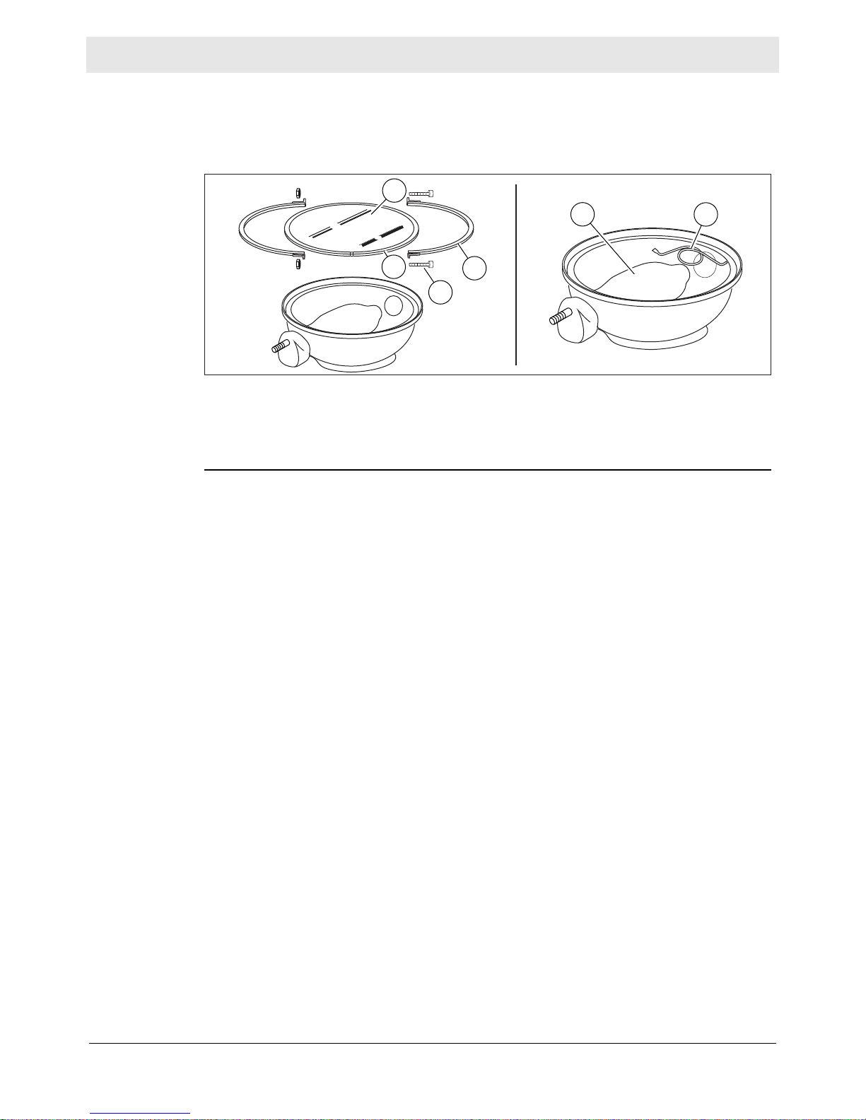
General Maintenance LTV
wc_gr005881
a
f
e
d
b
c
Continued from the previous page.
Perform the procedures below to remove and install the lamp.
Removing the
lamp
Installing the
lamp
1. Remove the screws (a) securing the flange rings (b) and remove the flange
rings.
2. Remove the lens (c) with the gasket (d) attached.
3. Remove the hardware securing one side of the lamp stabilizer (e). Once
removed, swing the lamp stabilizer to the side and unscrew the lamp (f).
1. Screw the lamp in firmly, but not forcibly, to minimize loosening due to vibration.
Secure it with the lamp stabilizer.
2. Install the gasket around the lens and secure the lens to the reflector with the
flange rings and screws.
84
wc_tx004457gb_FM10.fm
Page 85

LTV General Maintenance
7.8 Long-Term Storage
Introduction
When
Preparing for
storage
Stabilizing the
fuel
Extended storage of equipment requires preventive maintenance. Performing
these steps helps to preserve machine components and ensures the machine will
be ready for future use. While not all of these steps necessarily apply to this
machine, the basic procedures remain the same.
Prepare your machine for extended storage if it will not be operated for 30 days or
more.
Perform the procedures below to prepare your machine for storage.
■ Complete any needed repairs.
■ Replenish or change oils (engine, exciter, hydraulic, and gearcase) per the
intervals specified in the Scheduled Maintenance table.
■ Grease all fittings and, if applicable, repack bearings.
■ Inspect engine coolant. Replace coolant if it appears cloudy, is more than two
seasons old, or does not meet the average lowest temperature for your area.
■ If your machine has an engine equipped with a fuel valve, start the engine, close
the fuel valve, and run the engine until it stops.
■ Consult the engine owner’s manual for instructions on preparing the engine for
storage.
After completing the procedures listed above, fill the fuel tank completely and add a
high-quality stabilizer to the fuel.
■ Choose a stabilizer that includes cleaning agents and additives designed to
coat/protect the cylinder walls.
■ Make sure the stabilizer you use is compatible with the fuel in your area, fuel
type, grade and temperature range. Do not add extra alcohol to fuels which
already contain it (for example, E10).
■ For engines with diesel fuel, use a stabilizer with a biocide to restrict or prevent
bacteria and fungus growth.
■ Add the correct amount of stabilizer per the manufacturer’s recommendations.
Storing the
machine
wc_tx004457gb_FM10.fm
Perform these remaining steps to store your machine.
■ Wash the machine and allow it to dry.
■ Move the machine to a clean, dry, secure storage location. Block or chock the
wheels to prevent machine movement.
■ Use touch-up paint as needed to protect exposed metal against rust.
■ If the machine has a battery, either remove or disconnect it.
NOTICE: Allowing the battery to freeze or completely discharge is likely to cause
permanent damage. Periodically charge the battery while the machine is not in
use. In cold climates, store and charge the battery indoors or in a warm location.
■ Cover the machine. Tires and other exposed rubber items should be protected
from the weather. Either cover them or use a readily available protectant.
85
Page 86

General Maintenance LTV
7.9 Machine Disposal and Decommissioning
Introduction
Preparation
Disposal
This machine must be properly decommissioned at the end of its service life.
Responsible disposal of recyclable components, such as plastic and metal,
ensures that these materials can be reused—conserving landfill space and
valuable natural resources.
Responsible disposal also prevents toxic chemicals and materials from harming
the environment. The operating fluids in this machine, including fuel, engine oil,
and grease, may be considered hazardous waste in many areas. Before
decommissioning this machine, read and follow local safety and environmental
regulations pertaining to the disposal of construction equipment.
Perform the following tasks to prepare the machine for disposal.
Move the machine to a protected location where it will not pose any safety
hazards and cannot be accessed by unauthorized individuals.
Ensure that the machine cannot be operated from the time of final shutdown to
disposal.
Drain all fluids, including fuel, engine oil, and coolant.
Seal any fluid leaks.
Perform the following tasks to dispose of the machine.
Disassemble the machine and separate all parts by material type.
Dispose of recyclable parts as specified by local regulations.
Dispose of all non-hazardous components that cannot be recycled.
Dispose of waste fuel, oil, and grease in accordance with local environmental
protection regulations.
86
wc_tx004457gb_FM10.fm
Page 87

Engine Maintenance: Kubota D1005 / D1105
temperatures as shown below:
Recommended API classification
Oil used in the engine should have API classification and Proper SAE Engine Oil according to the ambient
Above 25°C (77°F) SAE30, SAE10W-30 or 15W-40
EGR: Exhaust Gas Re-circulation
SAE10W-30 or 15W-40
Below -10°C (14°F)
-10 to 25°C (14°F to 77°F)
Fuel type
SAE10W-30
Engine oil classification (API classification)
Engines with external EGR
Engines with non-EGR
Engines with internal EGR
High Sulfur Fuel
[0.05 % (500 ppm)
Sulfur Content <
0.50 % (5000 ppm)]
---
Ultra Low Sulfur Fuel
[Sulfur Content <
0.0015 % (15 ppm)]
CF, CF-4, CG-4, CH-4 or CI-4
CF
(If the "CF-4, CG-4, CH-4 or CI-4" engine oil is used
with a high-sulfur fuel, change the engine oil at
shorter intervals. (approximately half))
CF or CI-4
(Class CF-4, CG-4 and CH-4 engine, oils
cannot be used on EGR type engines.)
Refer to the following table for the suitable American Petroleum Institute (API) classification of engine oil according
to the engine type (with intern al EGR, external EGR or no n-EGR) an d the Fuel Type Used : (Ultr a Low Sulfur or
High Sulfur Fuels).
770030
8 Engine Maintenance: Kubota D1005 / D1105
The information in this chapter comes from copyrighted Kubota material.
The viscosity of the engine oil is an important factor when determining the correct
engine oil to use in your machine. Use an engine oil of app ropriate viscosity based
on the expected outside air temperature. See the table below.
WARNING
Most used liquids from this machine such as oil, gasoline, grease, etc., contain
small amounts of materials that can cause cancer and other health problems if
inhaled, ingested, or left in contact with skin for prolonged periods of time.
► Take steps to avoid inhaling or ingesting used liquids.
► Wash skin thoroughly after exposure to used liquids.
wc_tx004458gb_FM10.fm
87
Page 88

Engine Maintenance: Kubota D1005 / D1105
Interval Item
Every 50 hours @
SERVICE INTER V ALS
Observe the following for service and maintenance.
See NOTE
Check of fuel pipes and clamp bands
Change of engine oil
Every 100 hours
*1 @Cleaning of air cleaner element
Cleaning of fuel filter
Check of fan belt tightness
Every 200 hours
Draining water separator
Check of radiato r ho ses and clamp band s
@
Every 400 hours
Check of intake air line
Replacemen t of oi l filt er cartridge
(oil pan depth: 90 mm (3.54 in.))
@
Every 500 hours
Cleaning of water separator
Replacemen t of oi l filt er cartridge
(oil pan depth: 124 mm (4.88 in.))
Removal of sediment in fuel ta nk
Every year
Replacement of f an belt
Cleaning o f water jacket (r adiator interio r)
*2 @Replacement of air cleaner element
Every 800 hours
Check of damage in electric wiring and loose
connections
Every 1500 hours
Check of valve clearance
*3 @
Every 3000 hours
*3 @
Check of fuel injection nozzle injection pressure
Check of turbo cha rg er
*3 @Check of injection pump
Every two years
Change of radi at or coolant (L.L.C.)
Replacement of radiator hoses and c la mp bands
*3 @Replacement of f uel pi pes and clamp band s
*4 @
Replacemen t of i nt ake air line
770028
The engine maintenance schedule(s) in this chapter are reproduced from the
engine owner’s manual. For additional information, see the engine owner’s
manual.
88
wc_tx004458gb_FM10.fm
Page 89

Engine Maintenance: Kubota D1005 / D1105
*
The jobs indicated by must be done after the first 50 hours of operation.
**2 After 6 times of cleaning.
*
1 Air cleaner should be cleaned more often in dusty conditions than in normal conditions.
3 Consult your local KUBOTA Dealer for this service.
4 Replace only if necessary.
When the battery is used for less than 100 hours in a year, check its electrolyte yearly. (for refillable battery's only)
The items listed above (@ marked) are registered as emission related critical parts by KUBOTA in the U.S. EPA
*
Changing interval of engine oil
101 mm oil pan depth is optional.
**Standa rd rep lace men t interv al
nonroad emission regulation. As the engine owner, you are responsible for the performance of the required
maintenance on the engine according to the above instruction.
Please see the Warranty Statement in detail.
API service classification: above CF grade
Ambient temperature: below 35°C (95°F)
Oil pan depth
Models
*
Above 125 mm (4.9 in.)
(110 mm D1305-E3)
below 101 mm
(4.0 in.)
All models 200 Hrs 150 Hrs
Initial 50 Hrs
770029
NOTICE: When using SAE 15W-40 oil with Kubota powered machines, the oil
change interval is 750 hours.
wc_tx004458gb_FM10.fm
89
Page 90

Engine Maintenance: KOHLER
9 Engine Maintenance: KOHLER
The information in this chapter comes from copyrighted Kohler material.
The viscosity of the engine oil is an important factor when determining the correct
engine oil to use in your machine. Use an engine oil of appropriate viscosity based
on the expected outside air temperature. See the table below.
WARNING
Most used liquids from this machine such as oil, gasoline, grease, etc., contain
small amounts of materials that can cause cancer and other health problems if
inhaled, ingested, or left in contact with skin for prolonged periods of time.
► Take steps to avoid inhaling or ingesting used liquids.
► Wash skin thoroughly after exposure to used liquids.
90
wc_tx004459gb_FM10.fm
Page 91

SLCH-4 CG-4 CF-4
SJ
SH
BENZIN - GASOLINA
GASOLINE - BENZINA - ESSENCE
OBSOLETE - OBSOLETICURRENT - CORRENTI
L- 46152 D / E
Engine Maintenance: KOHLER
770005
***
Base Sintetica
Base Sintetica
Synthetic Base
Base Sintética
Base Synthétique
Synthetische Basis
**
Base Semi-Sintetica
Base Semi-Sintetica
Semi-Synthetic Base
SAE Viscosity Grade - Gradazioni SAE - Viscosité SAE
SAE Viskositätsklasse - Viscosidad SAE - Gradação SAE
*
Mineral Base
Base Semi-Sintética
Halbsynthetische Basis
Base Semi-Synthétique
Base Mineral
Base Mineral
Base Minerale
Base Minérale
Mineralölbasis
API/MIL-SEQUENZEN - SECUENCIAS API/MIL - SEQUÊNCIAS API/MIL
OIL CLASSIFICATIONS API/MIL - SEQUENZE API/MIL - SEQUENCES API/MIL
DIESEL
CF CE CD CC SC SD SE SF SG
CF-2
API
MIL
122
113
104
95
86
77
68
59
50
41
32
23
14
5
-4
-13
-22
-31
-40
F°
50
45
40
35
30
25
20
15
10
5
0
-5
-10
-15
SAE 10W
-20
-25
-30
-35
-40
C°
SAE 40
SAE 30
SAE 20W
SAE 10W-30
SAE 10W-40
SAE 10W-60
SAE 15W-40*
SAE 15W-40**
SAE 20W-60**
SAE 10W-30***
SAE 5W-30***
wc_tx004459gb_FM10.fm
91
Page 92

Engine Maintenance: KOHLER
OPERATION DESCRIPTION - DESCRIZIONE OPERAZIONE
DESCRIPTION DE L’OPÉRATION - BESCHREIBUNG DES ARBEITSVORGANGS
DESCRIPCIÓN DE LA OPERACIÓN - DESCRIÇÃO DA OPERAÇÃO
FREQUENCY x HOURS - PERIODICITA’ x ORE
FREQUENCE x HEURES - WARTUNGSPERIODEN x STUNDEN
PERIODO x HORAS - FREQUÉNCIA x HORAS
Oil Level - Livello Olio Motore - Niveau huile Moteur - Ölstanddaten - Nivel Aceite Del Motor - Nivel Óleo
do Motor
- Nivel Liquido para Refrigeración - Nivel Liquido Esfriamento.
Troca do Radiador
Panel Air Filter (Dry-Type) - Filtro Aria a Pannello (a Secco) - Filtre à Air à Panneau (à Sec) -
Remote Air Filter (Dry-Type) - Filtro Aria a Distanza (a Secco) - Filtre à Air à Distance (à Sec)
Combustíveis
Fan/Alternator Belt Tension - Tensione Cinghia Ventola/Alternatore - Tension Courroie Ventilateur/
Alternateur Keilriemens Lüfter - Tensión Correa Ventilador/Alternador - Tensão Cincha Ventilador/
Alternador
(***)
(***)
(*)
CHECK - CONTROLLO - CONTRôLE - KONTROLLE - COMPROBACìON - CONTRô LE
ORDINARY MAINTENANCE - MANUNTENZIONE ORDINARIA
ENTRETIEN ORDINAIRE - ORDENTLICHE WARTUNG
MANUTENCION ORDINARIA - MANUNTENAÇÃO NORMAL
10 250 300 500 1000 5000 10000
(***) - Check paper element for dirty, loose, or damaged parts, in accordance with the maintenance schedule. Depending on the environment the engine is used in, clean and replace
, dirty conditions.
-
-
- Das Zeitintervall zwischen den Reinigungen oder dem Auswechseln des Filterelements hängt von der Umgebung ab, in der der Motor verwendet wird. In sehr staubiger
- . En ambientes muy polvorientos
-
770002
The engine maintenance schedule(s) in this chapter are reproduced from the
engine owner’s manual. For additional information, see the engine owner’s
manual.
92
wc_tx004459gb_FM10.fm
Page 93

FREQUENCY x HOURS - PERIODICITA’ x ORE
Engine Maintenance: KOHLER
770003
PERIODO x HORAS - FREQUÉNCIA x HORAS
FREQUENCE x HEURES - WARTUNGSPERIODEN x STUNDEN
10 250 300 500 1000 5000 10000
(*)
(**)
wc_tx004459gb_FM10.fm
OPERATION DESCRIPTION - DESCRIZIONE OPERAZIONE
DESCRIPCIÓN DE LA OPERACIÓN - DESCRIÇÃO DA OPERAÇÃO
CHECK - CONTROLLO - CONTRôLE - KONTROLLE - COMPROBACÍON - CONTRô LE
DESCRIPTION DE L’OPÉRATION - BESCHREIBUNG DES ARBEITSVORGANGS
Cooling Hoses - Manicotti Liquido di Raffreddamento - Manchons de Liquide de Refroidissement - Muffen
des Kühlmittels - Manguitos de Líquido de Refrogeración - Casquilhos para Líquido de Arrefecimento
Rubber Intake Hose (Air Filter and Intake Manifold) for Engines with Remote Air F ilter - Tubo in Gomma
Asp. (Filtro Aria Coll. Asp.) P er Mot. C on Filtro Aria a Dist. - T uyau d’ A spiration en C aoutchouc (Filtre à Air
du Collecteur d’Admission) Pour Mot. Avec Système de Filtrage d’ A ir à D istance - Gummiansaugschlauch
Aire Colector de Admisión) Para Mot. Con Filtro de Aire Remoto - Tubo de Borracha de Aspiração (Filtro
ar Colector de Aspiração) Para Mot. com Filtro de ar a Distância
Valve Clearance - Registro Gioco Valvole - Réglage Jeu Soupapes - Einstallen des Ventilspiels Ajuste
da Tolarância - Registro Juego de Válvulas - Apuramento válvula
93
Injector Cleaning and Adjustment - Taratura e Pulizia Iniettori - Tarage et Nettoyage Injecteur
Einspritzdüsen Überprüfen - Ajuste y Limpieza Inyectores - Taradura e Limpeza Injectores
Flush Radiator - Pulizia Interna Radiatore - Nettoyage Intérieur du Radiateur - Innenreinigung des Kühlers
- Limpieza del Interior del Radiador - Limpeza Interna do Radiador
Clean Fuel Tank - Pulizia Serbatotio Combustibile - Nettoyage du Réservoir à Combustible - Reinigung
Kraftstofftank - Limpieza Depósito Combustible - Limpeza do Depósito do Combustível
Page 94

Engine Maintenance: KOHLER
REPLACEMENT - SOSTITUZIONE - REMPLACEMENT - AUSWECHSELN - SUSTITUCIÓN - SUBSTITUIÇÃO
OPERATION DESCRIPTION - DESCRIZIONE OPERAZIONE
DESCRIPTION DE L’OPÉRATION - BESCHREIBUNG DES ARBEITSVORGANGS
DESCRIPCIÓN DE LA OPERACIÓN - DESCRIÇÃO DA OPERAÇÃO
(°)
FREQUENCY x HOURS - PERIODICITA’ x ORE
FREQUENCE x HEURES - WARTUNGSPERIODEN x STUNDEN
PERIODO x HORAS - FREQUÉNCIA x HORAS
Engine Oil (°) - Olio Motore (°) - Huile Moteur (°) - Öldaten (°) - Aceite del Motor (°) - Óleo do Motor (°)
Oil Filter - Filtro Olio - Filtre a Huile - Öl Filter - Filtro Aceite - Filtro Óleo
Alternator Belt - Cinghia Alternatore - Courroie Alternateur - Drehstromgenerator Riemen - Correa Alternador - Cincha
Alternador
Rubber Intake Hose (Air Filter and Intake Manifold) - Tubo in Gomma Asp. (Filtro Aria Coll. Asp.) - Tuyau d’aspir. en
Admis (Filtro de Aire Col. De Admis.) - Tubo de Borracha de Aspir. (Filtro ar Col. de Aspir.)
Coolant Hoses - Manicotti Liquido di Raffredd. - Manchons de Liquide de Refroid. - Muffen des Kühlmittels - Manguitos
de
Líquido de Refriger - Casqilhos para Líquido de Arrefecimento
Timing Belt - Cinghia Distribuzione - Courroie de Distribution - Verteilerriemen Correa de Distribución - Correia de Distribuição
Dry Air Cleaner, External Cartridge - Cartuccia Esterna Filtro Aria a Secco - Cartouche Extérieure Filtre a Air
Seco
Filter Element, Panel Air Filter - Massa Filtrante Filtro Aria a Pannello - Masse Filtrante de Filtre à Air á Panneau
10 250 300 500 1000 5000 10000
- If you are using oil of a quality lower than the prescribed one then you will have to replace it every 125 hours for the standard sump and every 150 hours for the enhanced sump.
- Se si utilizza olio di qualità inferiore a quello prescritto sostituirlo ogni 125 ore per la coppa standard e 150 per la coppa maggiorata.
- Si l’huile utilisée est de qualité inférieure à celle indiqué, la vindanger toutes les 125 heures s’il s’agit d’un carter standard et toutes les 150 heures s’il s’agit d’un carter
surdimensionné.
- Wenn Öl einer niedrigeren Qualität als vorgeschriebenen verwendet wird, sollte es bei Standardölwannen alle 125 Betriebsstunden, bei vergrößererten Ölwannen alle 150
Stunden gewechselt werden.
- Si se utiliza un aceite de calidad inferior al que recomendado deberà sustituirse cada 125 horas en caso de càrter estàndar o cada 150 en caso de càrter sobredimensionado.
- Se utilizar óleo de qualidade inferior à quele prescrito, substitua- o a cada 125 horas para o càrter padrao e 150 para o càrter aumentado.
After six cleaning checks - Dopo 6 Controlli con Pulizia - Au
Bout de 6 Contrôles Avec Nettoyage - Nach 6 Kontrollen
Mit Reinigung - Tras 6 Inspecciones Con Limpieza - Após 6
Controlos com Limpeza
Every 4000 hours or 4 Years - Ogni 4000 ore o 4 anni - Toutes les
4000 heures ou 4 ans - Alle 4000 Stunden und 4 yahre - Cada 4000
horas o 4 anos - Cada 4000 oras o 4 anos
(*)
(*)
(*)
(**)
(**)
(**)
(****)
(**)
(**)
(***)
770004
NOTICE: When using AGIP SINT 2000 5W-40 oil with Kohler powered machines, the oil change interval is 750 hours.
94
wc_tx004459gb_FM10.fm
Page 95

LTV Troubleshooting
10 Troubleshooting
WARNING
HIGH VOLTAGE! This unit uses high voltage circuits capable of causing serious
injury or death.
► Only a qualified electrician should troubleshoot or repair electrical problems
occurring in this equipment.
Problem Cause Remedy
Engine doesn’t start Battery discharged Charge battery.
Battery connections corroded Clean battery connections.
Blown fuse Replace fuse.
Faulty starter Replace starter.
Engine tries to start
but stops
No generator output Main circuit breaker open Close main circuit breaker.
Low oil pressure Low oil level Fill engine sump with oil.
High coolant
temperature
Engine emits black
smoke
No fuel Fill tank with fuel.
Bleed fuel lines.
Clogged fuel filter Replace fuel filter.
Fuel circuit failure Check fuel lines.
Voltage regulator malfunction Call Wacker Neuson for service.
Clogged oil filter Replace oil filter.
Oil pump failure Call Wacker Neuson for service.
Electrical overload Reduce load.
Low coolant level Fill with coolant.
Low oil level Fill sump with oil.
Clogged oil filter Replace oil filter.
Clogged air filter Clean/replace air filter cartridges.
Electrical overload Reduce load.
High oil level Remove excess oil.
Fuel circuit failure Call Wacker Neuson for service.
wc_tx004456gb_FM10.fm
95
Page 96

Troubleshooting LTV
Problem Cause Remedy
Lamp will not light Lamp is too hot Allow lamp to cool 10–15 minutes before
restarting.
Faulty lamp connection Check that lamp is tight in socket. Check
connections inside connection boxes on
light fixtures and tower.
Plug connection at fixture is loose or
damaged
Lamp broken or burned out Check for:
Circuit breaker turned on Turn off circuit breaker.
Circuit breaker loose or faulty Repair or replace the circuit breaker.
Generator output incorrect Check incoming voltage to ballast.
Low or no ballast output With the fixture cord removed from its
Low light output Lamp degraded Replace lamp due to normal lamp life.
Repair or replace the plug connection.
■ broken arc tube or outer lamp jacket,
■ broken or loose components in lamp
envelope,
■ or blackening or deposits inside lamp
tube.
Incoming voltage should be 120V ± 5V. If
voltage is incorrect, engine speed may
need to be adjusted or generator may
require service.
receptacle, the voltage should measure
400 to 445 VAC. If proper voltage is not
achieved, perform capacitor check to
determine if capacitor or coil needs to be
replaced.
Low ballast output Check ballast for prope r vo ltage outpu t.
Fixture or lens dirty Clean reflective surface inside fixture and
both inside and outside surface of glass
lens.
wc_tx004456gb_FM10.fm
96
Page 97

LTV Technical Data
11 Technical Data
11.1 Engine—KUBOTA
Engine Power Rating
Net power rating per ISO 3046 IFN. Actual power output may vary due to
conditions of specific use.
Machine LTV6K LTV8K
Engine
Make Kubota
Model D1005 D1105
Type 3-cylinder, 4-cycle, liquid-cooled diesel
Max. rated power @ rated
speed
Operating speed
(no-load)
Alternator V / A / W 12 / 30 / 360
Battery V/Ah/ccA 12 / 650
Air cleaner type Dry-type element
Fuel type No. 2 diesel
Fuel tank capacity L (gal) 173.3 (45.8)
Fuel consumption L (gal) / hr 2.58 (0.68) 2.97 (0.79)
Running time (100% load) hours 64.3 55.7
Coolant capacity L (qt) 5.78 (4.7)
Oil capacity L (qt) 5.1 (5.4)
Oil grade SAE / API 15W40 / CF or higher
kW (hp) 9.8 (13.1)
@ 1800 rpm
rpm 1800
11.5 (15.4)
@ 1800 rpm
wc_tx004432gb_FM10.fm
97
Page 98

Technical Data LTV
11.2 Engine—KOHLER
Engine Power Rating
Net power rating per ISO 3046 IFN. Actual power output may vary due to
conditions of specific use.
Machine LTV6L
Engine
Make Kohler
Model LDW1003
Type 3-cylinder, 4-cycle, liquid-cooled diesel
Max. power rating @ rated
speed
Operating speed
(no-load)
Alternator V / A / W 12 / 45 / 540
Battery V/Ah/ccA 12 / 650
Air cleaner type Dry-type element
Fuel type No. 2 diesel
Fuel tank capacity L (gal) 173.3 (45.8)
Fuel consumption L (gal) / hr 1.68 (0.44)
Running time (100% load) hours 60.5
Coolant capacity L (qt) 4.7 (5.0)
Oil specification type AGIP SINT 2000 5W-40
Oil capacity L (qt) 3.8 (4.0)
kW (hp) 8.0 (10.7) @ 1800 rpm
rpm 1800
API SJ / CF 4
ACEA A3-96 B3-96
MIL-L-46152 D/E
98
wc_tx004432gb_FM10.fm
Page 99

LTV Technical Data
11.3 Generator
Machine: LTV6 LTV8
Frequency Hz 60
Continuous output kW 6.0 8.0
Output volts/phase 120/240, 1Ø (6K)
120, 1Ø (6L)
Amps A 50/25 66/33
Excitation type Capacitor / Brushless
Power factor 1.0
Voltage regulation - No load
to full load
Speed (no-load) rpm 1800
%± 6.0
120/240, 1Ø
wc_tx004432gb_FM10.fm
99
Page 100

Technical Data LTV
11.4 Machine
LTV6K LTV6L LTV8K
Model Unit
LTV6K LTV6L (C.W.) LTV8K (C.W.)
Dimensions
(L x W x H)
Operating weight kg (lbs) 812 (1790) 798 (1760) 812 (1790)
Height - mast extended m (ft) 6.9 (22.7) 6.9 (22.7) 6.9 (22.7)
Output kW 6 6 8
AC Voltage V 120/240 120 (120/240 with
Amperage A 50/25 50/25 66/33
Frequency Hz 60 60 60
Power factor # 1 1 1
Lamp type Metal halide Metal halide Metal halide
Lamp wattage W
NEMA beam spread type 6 6 6
Maximum lighting
coverage @ 5.0
ft-candles
cm
(in)
2
(ft2) 1200 (12,918) 1200 (12,918) 1200 (12,918)
m
256 X 146 X 251
(101 X 58 X 99)
1100 1100 1100
256 X 146 X 251
(101 X 58 X 99)
twist-lock option)
256 X 146 X 251
(101 X 58 X 99)
120/240
Sound level @ 7m (23ft) dB(A) 68.3 67.9 70.1
AC outlet receptacles V, A
type
1 X 125, 20, Duplex
GFCI
1 X 120/240, 30,
Twist-lock
1 X 120, 20, Duplex
GFCI
2 X 125, 20, Duplex
GFCI
1 X 120/240, 30,
Twist-lock
100
wc_tx004432gb_FM10.fm
 Loading...