

Page 1
Operator’s Manual
5200004275
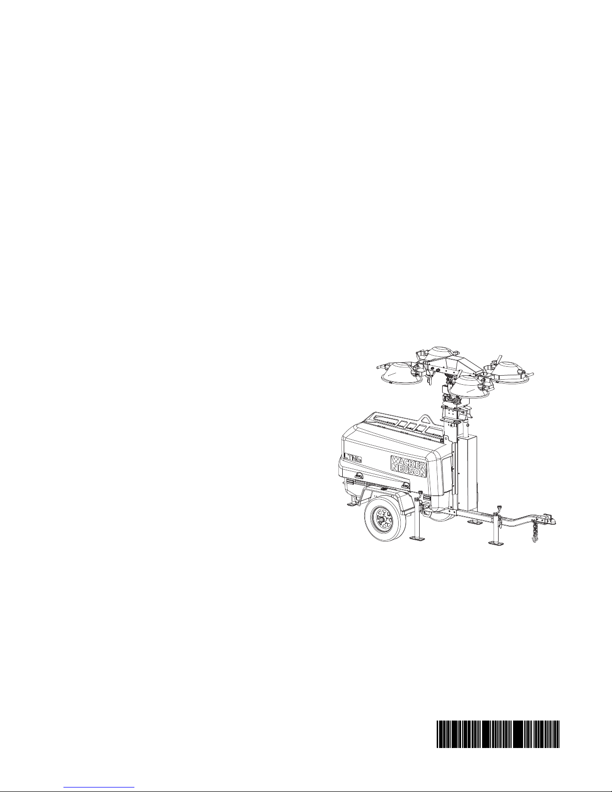
Light Tower
LTN 6K-V, LTN 6K-VS
LTN 8K-V, LTN 8K-VS
LTN 6L-VS 60 Hz
Type LTN 6K-V, LTN 6K-VS, LTN 8K-V, LTN
Document 5200004275
Date 1115
Version 03
Language EN
8K-VS, LTN 6L-VS (60 Hz)
Page 2

Copyright notice
© Copyright 2015 by Wacker Neuson Production Americas LLC
All rights, including copying and distribution rights, are reserved.
This publication may be photocopied by the original purchaser of the
machine. Any other type of reproduction is prohibited without express
written permission from Wacker Neuson Production Americas LLC.
Any type of reproduction or distribution not authorized by Wacker
Neuson Production Americas LLC represents an infringement of valid
copyrights. Violators will be prosecuted.
Trademarks
Manufacturer
Original instructions
All trademarks referenced in this manual are the property of their
respective owners.
Wacker Neuson Production Americas LLC
N92W15000 Anthony Avenue
Menomonee Falls, WI 53051 U.S.A.
Tel: (262) 255-0500 · Fax: (262) 255-0550 · Tel: (800) 770-0957
www.wackerneuson.com
This Operator’s Manual presents the original instructions. The original
language of this Operator’s Manual is American English.
Page 3
LTN Foreword
Foreword
SAVE THESE INSTRUCTIONS—This manual contains important instructions for
the machine models below. These instructions have been written expressly by
Wacker Neuson Production Americas LLC and must be followed during inst allation,
operation, and maintenance of the machines.
Machines
covered in
this manual
Machine Item Number
LTN 6K-V 5200002722, 5200002726
LTN 8K-V 5200002727, 5200002728
LTN 6K-V S 5200018537, 5200018550, 5200018553
LTN 8K-V S 5200018538, 5200018551, 5200018554
LTN 6L-V S 5200018536, 5200018539, 5200018552
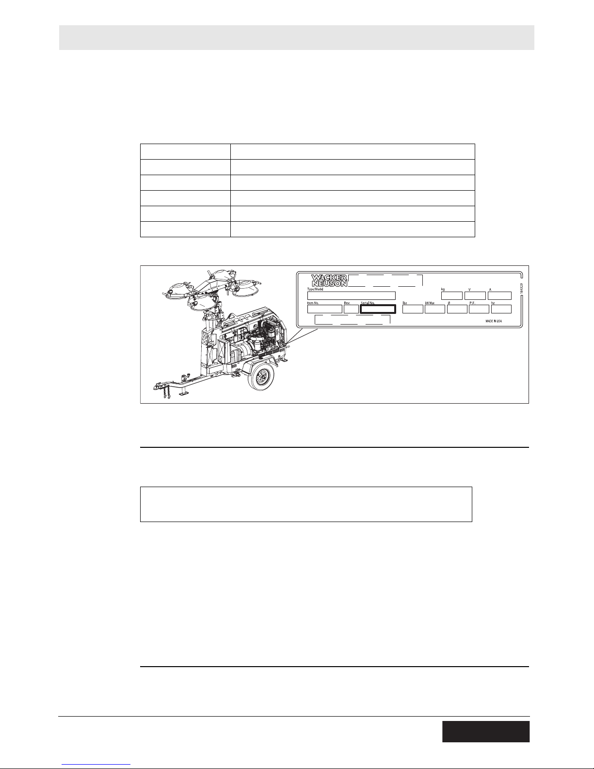
Machine
identification
Serial number
(S/N)
Machine
documentation
wc_gr010093
A nameplate listing the model number, item number, revision number, and serial
number is attached to this machine. The location of the nameplate is shown above.
For future reference, record the serial number in the space provided below . You will
need the serial number when requesting parts or service for this machine.
Serial Number:
From this point forward in this documentation, Wacker Neuson Production
Americas LLC will be referred to as Wacker Neuson.
Keep a copy of the Operator’s Manual with the machine at all times.
Use the separate Parts Book supplied with the machine to order replacement
parts.
If you are missing either of these documents, please conta ct W acker Neuson to
order a replacement or visit www.wackerneuson.com.
When ordering parts or requesting service information, be prepared to provide
the machine model number, item number, revision number, and serial number.
wc_tx003092gb.fm 3
Page 4

Foreword LTN
Expectations
for
information in
this manual
Manufacturer’s
approval
This manual provides information and procedures to safely operate and main-
tain the above Wacker Neuson model(s). For yo ur own safety and to reduce the
risk of injury, carefully read, understand, and observe all instructions described
in this manual.
Wacker Neuson expressly reserves the right to make technical modifications,
even without notice, which improve the performance or safety standards of its
machines.
The information contained in this manual is based on machines manufactured
up until the time of publication. Wacker Neuson reserves the right to change
any portion of this information without notice.
The illustrations, parts, and procedures in this manual refer to Wacker Neuson
factory-installed components. Your machine may vary depending on the
requirements of your specific region.
This manual contains references to approved parts, attachments, and
modifications. The following definitions apply:
Approved parts or attachments are those either manufactured or provided by
Wacker Neuson.
Approved modifications are those performed by an authorized Wacker Neu-
son service center according to written instructions published by Wacker Neuson.
Unapproved parts, attachments, and modifications are those that do not
meet the approved criteria.
Unapproved parts, attachments, or modifications may have the following
consequences:
Serious injury hazards to the operator and persons in the work area
Permanent damage to the machine which will not be covered under warranty
Contact your Wacker Neuson dealer immediately if you have questions about
approved or unapproved parts, attachments, or modifications.
CALIFORNIA
Proposition
65 Warning
Laws
pertaining to
spark
arresters
Combustion exhaust, some of its constituents, and certain vehicle components
contain or emit chemicals known to the State of California to cause cancer and
birth defects or other reproductive harm.
NOTICE: State Health Safety Codes and Public Resources Codes specify that in
certain locations spark arresters be used on internal combustion engines that use
hydrocarbon fuels. A spark arrester is a device designed to prevent accidental discharge of sparks or flames from the engine exhaust. Spark arresters are qualified
and rated by the United States Forest Service for this purpose. In order to comply
with local laws regarding spark arresters, consult the engine distributor or the local
Health and Safety Administrator.
4 wc_tx003092gb.fm
Page 5

LTN
Table of Contents
Foreword 3
1 Safety Information 9
1.1 Signal Words Used in this Manual ....................................................... 9
1.2 Machine Description and Intended Use ............................................. 10
1.3 Safety Guidelines for Operating the Machine ..................................... 11
1.4 Service Safety .................................................................................... 14
1.5 Operator Safety while Using Internal Combustion Engines ............... 16
1.6 Safety Guidelines for Lifting and Transporting the Machine ............... 17
1.7 Safety Guidelines for Towing the Machine ......................................... 18
1.8 Reporting Safety Defects ................................................................... 19
2 Labels 20
2.1 Label Locations .................................................................................. 20
2.2 Label Meanings .................................................................................. 22
3 Lifting and Transporting 31
3.1 Lifting the Machine ............................................................................. 31
3.2 Preparing the Machine for Transport on a Truck or Trailer ................ 32
3.3 Preparing the Machine for Towing ..................................................... 33
3.4 Towing the Machine ........................................................................... 34
4 Operation 35
4.1 Preparing the Machine for First Use ................................................... 35
4.2 Generator Derating ............................................................................. 35
4.3 Positioning the Machine ..................................................................... 36
4.4 Ground Connection ............................................................................ 37
4.5 Leveling Trailer ................................................................................... 38
4.6 Refueling the Machine ........................................................................ 39
4.7 Aiming the Lights - LTN-V .................................................................. 40
4.8 Control Panels .................................................................................... 43
4.9 Control Panels - LTN 6L-VS ............................................................... 44
4.10 Before Starting ................................................................................... 45
4.11 Starting the Machine - LTN 6K-V, LTN 8K-V ...................................... 46
4.12 Starting the Machine - LTN 6L ........................................................... 47
4.13 Operating the Lights ........................................................................... 48
4.14 Raising the Tower - LTN -V ................................................................ 49
4.15 Manually Rotating the Mast ................................................................ 50
wc_bo5200004275_03TOC.fm
5
Page 6

Table of Contents
4.16 Lowering the Tower .............................................................................51
4.17 Automatic Shutdown ...........................................................................52
4.18 Stopping the Machine - LTN 6K/8K-V .................................................52
4.19 Stopping the Machine - LTN 6L-V .......................................................53
4.20 Emergency Shutdown Procedure ........................................................54
4.21 Using the Convenience Receptacles - 60 Hz ......................................55
5 Factory-Installed Options 56
5.1 Engine Block Heater ............................................................................56
5.2 Battery Blanket ....................................................................................56
5.3 Oil Pan Heater .....................................................................................57
5.4 RCBO Circuit Breaker .........................................................................57
5.5 LED Lights ...........................................................................................58
6 Maintenance 59
LTN
6.1 Preparing for Maintenance ..................................................................59
6.2 Periodic Maintenance Schedule ..........................................................60
6.3 Cleaning the Machine ..........................................................................61
6.4 Inspecting the Machine .......................................................................62
6.5 Checking the Engine Oil ......................................................................63
6.6 Changing the Engine Oil .....................................................................64
6.7 Checking the Engine Coolant Level ....................................................65
6.8 Flushing the Radiator ..........................................................................66
6.9 Cleaning the Air Filter Element ............................................................68
6.10 Maintaining the Battery ........................................................................69
6.11 Checking Fan Belt Tension .................................................................70
6.12 Checking Radiator Hoses ....................................................................71
6.13 Performing Coolant Solution Analysis .................................................72
6.14 Testing the Cooling System Pressure .................................................73
6.15 Removing and Replacing Lamps ........................................................75
6.16 Long-Term Storage .............................................................................77
6.17 Machine Disposal / Decommissioning .................................................78
7 Engine Maintenance: Kubota (T4f) 80
8 Engine Maintenance: Kohler (T4f) 84
9 Troubleshooting 88
6
wc_bo5200004275_03TOC.fm
Page 7

LTN
Table of Contents
10 Technical Data 90
10.1 Engine - Kubota .................................................................................. 90
10.2 Engine - Kohler ................................................................................... 91
10.3 Generator ........................................................................................... 92
10.4 Machine .............................................................................................. 93
10.5 Radiation Compliance ........................................................................ 94
10.6 Dimensions - LTN 6K-V, LTN 8K-V .................................................... 94
10.7 Dimensions - LTN 6K-VS, LTN 8K-VS, LTN 6L-VS ........................... 94
11 Schematics 95
11.1 LTN 8K-V Lighting Schematic ............................................................ 95
11.2 Components ....................................................................................... 96
11.3 LTN 6K-V Lighting Schematic ............................................................ 97
11.4 Components ....................................................................................... 98
11.5 Generator Capacitor Excitation Schematic ........................................ 99
11.6 Engine Wiring ................................................................................... 100
11.7 Components ..................................................................................... 101
11.8 Hydraulic Schematic - LTN 6K-V, LTN 8K-V .................................... 102
11.9 Hydraulic Schematic- LTN 6K-VS, LTN 8K-VS ................................ 103
11.10 Trailer Wiring .................................................................................... 104
wc_bo5200004275_03TOC.fm
7
Page 8

Table of Contents
LTN
8
wc_bo5200004275_03TOC.fm
Page 9
LTN Safety Information
1 Safety Information
1.1 Signal Words Used in this Manual
This manual contains DANGER, WARNING, CAUTION, NOTICE, and NOTE
signal words which must be followed to reduce the possibility of personal injury,
damage to the equipment, or improper service.
This is the safety alert symbol. It is used to alert you to potential personal hazards.
f Obey all safety messages that follow this symbol.
DANGER
DANGER indicates a hazardous situation which, if not avoided, will result in death
or serious injury.
f To avoid death or serious injury from this type of hazard, obey all safety
messages that follow this signal word.
WARNING
WARNING indicates a hazardous situation which, if not avoided, could result in
death or serious injury.
f To avoid possible death or serious injury from this type of hazard, obey all safety
messages that follow this signal word.
CAUTION
CAUTION indicates a hazardous situation which, if not avoided, could result in
minor or moderate injury.
f To avoid possible minor or moderate injury from this type of hazard, obey all
safety messages that follow this signal word.
NOTICE: Used without the safety alert symbol, NOTICE indicates a situation
which, if not avoided, could result in property damage.
Note: A Note contains additional information important to a procedure.
wc_si000704gb.fm
9
Page 10

Safety Information LTN
1.2 Machine Description and Intended Use
Machine
description
Intended use
This machine is a mobile, trailer-mounted light tower. The Wacker Neuson Light
Tower consists of a trailer with a cabinet containing a diesel engine, a fuel tank, a
control panel, and an electric alternator. A telescoping tower with four metal halide
lights is vertically mounted to the top of the machine. A hydraulic cylinder,
combined with a cable and pulley system, raises and lowers the telescoping tower.
As the engine runs, the generator converts mechanical energy into electric power.
The metal halide lights run of f this power. Receptacle(s) are also provided to power
auxiliary loads. The operator uses the control panel to operate and monitor the
machine.
This machine is intended for the illumination of outdoor areas. This machine is also
intended for the purpose of supplying electrical power to connected loads. Refer to
the machine specifications for the output voltage and frequency, and for the
maximum output power limit of this Light Tower.
This machine has been designed and built strictly for the intended use described
above. Using the machine for any other purpose could permanently damage the
machine or seriously injure the operator or other persons in the area. Machine
damage caused by misuse is not covered under warranty. The following are some
examples of misuse:
Connecting a load that has voltage and frequency requirements that are
incompatible with the machine output
Overloading the machine with a device that draws excessive power during
either continuous running or startup
Operating the machine in a manner that is inconsistent with all federal, state,
and local codes and regulations
Using the machine as a ladder, support, or work surface
Using the machine to carry or transport passengers or equipment
Using the machine as a hoist, or hanging items from the tower
Operating the machine outside of factory specifications
Operating the machine in a manner inconsistent with all warnings found on the
machine and in the Operator’s Manual
This machine has been designed and built in accordance with the latest global
safety standards. It has been carefully engineered to eliminate hazards as far as
practicable and to increase operator safety through protective guards and labeling.
However, some risks may rema in even after protective measures have been t aken.
They are called residual risks. On this machine, they may include exposure to:
Heat, noise, exhaust, and carbon monoxide from the engine
Heat from the lights
Ultraviolet radiation from the lights
Fire hazards from improper refueling techniques
Fuel and its fumes
Electric shock and arc flash
Personal injury from improper lifting the trailer tongue
10
wc_si000704gb.fm
Page 11

LTN Safety Information
Glare from lights (lights may blind drivers of nearby motor vehicles if the lights
are incorrectly positioned)
Typical hazards related to towing a trailer on roads and highways
To protect yourself and others, make sure you thoroughly read and understand the
safety information presented in this manual before operating the machine.
1.3 Safety Guidelines for Operating the Machine
Operator
training
Operator
qualifications
Before operating the machine:
Read and understand the operating instructions contained in all manuals
delivered with the machine.
Familiarize yourself with the location and proper use of all controls and safety
devices.
Contact Wacker Neuson for additional training if necessary.
When operating this machine:
Do not allow improperly trained people to operate the machine. People
operating the machine must be familiar with the potential risks and hazards
associated with it.
Only trained personnel are permitted to start, operate, and shut down the machine.
They also must meet the following qualifications:
have received instruction on how to properly use the machine
are familiar with required safety devices
The machine must not be accessed or operated by:
children
people impaired by alcohol or drugs
Application
area
Safety
devices,
controls, and
attachments
wc_si000704gb.fm
Be aware of the application area.
Keep unauthorized personnel, children, and pets away from the machine.
Remain aware of changing positions and the movement of other equipment and
personnel in the application area/job site.
Be aware of the application area.
Do not operate the machine in areas that contain flammable objects, fuels, or
products that produce flammable vapors.
Only operate the machine when:
All safety devices and guards are in place and in working order.
All controls operate correctly.
The machine is set up correctly according to the instructions in the Operator’s
Manual.
The machine is clean.
The machine’s labels are legible.
To ensure safe operation of the machine:
11
Page 12

Safety Information LTN
Do not operate the machine if any safety devices or guards are missing or
inoperative.
Do not modify or defeat the safety devices.
Only use accessories or attachments that are approved by Wacker Neuson.
Safe
operating
practices
Personal
Protective
Equipment
(PPE)
Before
Starting
When operating this machine:
Remain aware of the machine’s moving parts. Keep hands, feet, and loose
clothing away from the machine’s moving parts.
When operating this machine:
Do not operate a machine in need of repair.
Wear the following Personal Protective Equipment (PPE) while operating this
machine:
Close-fitting work clothes that do not hinder movement
Safety glasses with side shields
Hearing protection
Safety-toed footwear
Be sure the machine is on a firm, level surface and will not tip, roll, slide, or fall
while operating.
Never connect machine to other power sources, such as supply mains of power
companies.
Never use the machine if the insulation on the electrical cord is cut or worn
through.
Never raise the tower or operate the machine in high winds.
The tower extends up to 8.7 m (28.54 ft.). Make sure the area above the trailer
is open and clear of overhead wires and obstructions.
Operation
After Use
Keep the area under and around the lights clear of people while raising and
lowering the tower.
Do not move the Light Tower while it is operating.
Stop the engine when the machine is not being operated.
Close the fuel valve on engines equipped with one when machine is not being
operated.
Ensure that the machine will not tip over, roll, slide, or fall when not being
operated.
Store the machine properly when it is not being used. The machine should be
stored in a clean, dry location out of the reach of children.
Lower the tower when not in use, or if high winds or electrical storms are
expected in the area.
The lamps become extremely hot in use! Allow the lamp and fixture to cool
10–15 minutes before handling.
Lamp Safety
wc_si000704gb.fm
12
Page 13

LTN Safety Information
Description
Operating
safety
The lamps provided with your Light Tower are electric discharge lamps. They are
designed for use with metal halide ballasts only, and require time to reach full
brightness on initial startup and after a power interruption. These lamps comply
with FDA regulation performance standards 21 CFR 1040-30.
WARNING
Personal injury hazard. Broken or punctured lamps can cause serious skin burns
and eye inflammation from shortwave ultraviolet radiation.
f Do not operate the Light Tower if a lamp is damaged.
f Replace damaged lamps immediately.
Replace damaged lamps according to the instructions in section Removing /
Replacing Lamps.
Alternative lamps that automatically extinguish when the outer envelope is
broken or punctured are commercially available.
wc_si000704gb.fm
13
Page 14

Safety Information LTN
1.4 Service Safety
Service
training
Precautions
Before servicing or maintaining the machine:
Read and understand the instructions contained in all manuals delivered with
the machine.
Familiarize yourself with the location and proper use of all controls and safety
devices.
Only trained personnel shall troubleshoot or repair problems occurring with the
machine.
Contact Wacker Neuson for additional training if necessary.
When servicing or maintaining this machine:
Do not allow improperly trained people to service or maintain the machine.
Personnel servicing or maintaining the machine must be familiar with the
associated potential risks and hazards.
Follow the precautions below when servicing or maintaining the machine.
Read and understand the service procedures before performing any service to
the machine.
All adjustments and repairs must be completed before operating the machine.
Do not operate the machine with a known problem or deficiency.
All repairs and adjustments shall be completed by a qualified technician.
Turn off the machine before performing maintenance or making repairs.
Remain aware of the machine’s moving parts. Keep hands, feet, and loose
clothing away from the machine’s moving parts.
Re-install the safety devices and guards after repair and maintenance
procedures are complete.
Machine
modifications
Replacing
parts and
labels
When servicing or maintaining the machine:
Use only accessories/attachments that are approved by Wacker Neuson.
When servicing or maintaining the machine:
Do not defeat safety devices.
Do not modify the machine without the express written approval of Wacker
Neuson.
Replace worn or damaged components.
Replace all missing and hard-to-read labels.
When replacing electrical components, use components that are identical in
rating and performance to the original components.
When replacement parts are required for this machine, use only Wacker
Neuson replacement parts or those p arts equivalent to the original in all types of
specifications, such as physical dimensions, type, strength, and material.
wc_si000704gb.fm
14
Page 15

LTN Safety Information
Cleaning
Personal
Protective
Equipment
(PPE)
When cleaning and servicing the machine:
Keep the machine clean and free of debris such as leaves, paper, cartons, etc.
Keep the labels legible.
When cleaning the machine:
Do not clean the machine while it is running.
Never use gasoline or other types of fuels or flammable solvents to clean the
machine. Fumes from fuels and solvents can become explosive.
Wear the following Personal Protective Equipment (PPE) while servicing or
maintaining this machine:
Close-fitting work clothes that do not hinder movement
Safety glasses with side shields
Hearing protection
Safety-toed footwear
In addition, before servicing or maintaining the machine:
Tie back long hair.
Remove all jewelry (including rings).
Before servicing the Light Tower, make sure the engine start switch is turned to
the OFF position, the circuit breakers are open (off), and the negative terminal
on battery is disconnected. Do not perform even routine service (oil/filter
changes, cleaning, etc.) unless all electrical components are shut down.
Always turn off light circuit breakers and shut down engine before disconnecting
light fixtures or changing light bulbs.
wc_si000704gb.fm
15
Page 16
Safety Information LTN
1.5 Operator Safety while Using Internal Combustion Engines
WARNING
Internal combustion engines present special hazards during operation and fueling.
Failure to follow the warnings and safety standards could result in severe injury or
death.
f Read and follow the warning instructions in the engine owner’s manual and the
safety guidelines below.
DANGER
Exhaust gas from the engine contains carbon monoxide, a deadly poison.
Exposure to carbon monoxide can kill you in minutes.
f NEVER operate the machine inside an enclosed area, such as a tunnel, unless
adequate ventilation is provided through such items as exhaust fans or hoses.
Operating
safety
Refueling
safety
When running the engine:
Keep the area around exhaust pipe free of flammable materials.
Check the fuel lines and the fuel tank for leaks and cracks before starting the
engine. Do not run the machine if fuel leaks are present or the fuel lines are
loose.
When running the engine:
Do not smoke while operating the machine.
Do not run the engine near sparks or open flames.
Do not touch the engine or muffler while the engine is running or immediately
after it has been turned off.
Do not operate a machine when its fuel cap is loose or missing.
Do not start the engine if fuel has spilled or a fuel odor is present. Move the
machine away from the spill and wipe the machine dry before starting.
When refueling the engine:
Clean up any spilled fuel immediately.
Refill the fuel tank in a well-ventilated area.
Replace the fuel tank cap after refueling.
Use suitable tools for refueling (for example, a fuel hose or funnel).
When refueling the engine:
Do not smoke.
Do not refuel a hot or running engine.
Do not refuel the engine near sparks or open flames.
16
wc_si000704gb.fm
Page 17

LTN Safety Information
1.6 Safety Guidelines for Lifting and Transporting the Machine
When lifting the machine:
Make sure slings, chains, hooks, ramps, jacks, forklifts, cranes, hoists, and any
other type of lifting device used is attached securely and has enough weightbearing capacity to lift or hold the machine safely. See section Technical Data
for machine weight.
Remain aware of the location of other people when lifting the machine.
Only use the lifting points and tie-downs described in the Operator’s Manual.
Make sure the transporting vehicle has sufficient load cap acity and platform size
to safely transport the machine.
To reduce the possibility of injury:
Do not stand under the machine while it is being lifted or moved.
Do not get onto the machine while it is being lifted or moved.
wc_si000704gb.fm
17
Page 18

Safety Information LTN
1.7 Safety Guidelines for Towing the Machine
WARNING
Risk of severe injury or death. Improper trailer condition and towing technique can
lead to an accident.
f Obey the trailer manufacturer’s instructions and the instructions below to reduce
the risk of an accident.
When towing the machine:
Do not tow the machine if the towing vehicle’s hitch or the trailer’s coupler are
damaged.
Do not tow the machine if any of the trailer’s lug nuts are missing.
Do not tow the machine if the trailer’s tires have less than 1.5 mm (1/16 inch) of
tread.
Do not tow the machine unless the trailer’s brakes are functioning properly.
Do not exceed the trailer manufacturer’s speed limitations.
When towing the machine:
Only tow the machine when the trailer’s lug nuts are properly torqued.
Only tow the machine when the trailer’s tires are properly inflated.
Only tow the machine when all trailer lights are functioning correctly.
Only tow the machine when the trailer’s safety chains are connected to the
towing vehicle in a crisscross pattern.
Maintain extra distance between the towing vehicle and other vehicles.
Avoid soft shoulders, curbs, and sudden lane changes.
Abide by all licensing requirements for your area.
If you have not driven a towing vehicle with trailer before, practice turning,
stopping, and backing up the towing vehicle with trailer in an area away from traffic.
Only drive the towing vehicle with trailer when you are confident in your ability to do
so.
18
wc_si000704gb.fm
Page 19

LTN Safety Information
1.8 Reporting Safety Defects
If you believe your trailer has a defect which could cause a crash or could cause
injury or death, you should immediately inform the National Highway Traffic Safety
Administration (NHTSA) in addition to notifying Wacker Neuson.
If NHTSA receives similar complaints, it may open an investigation; and if it finds
that a safety defect exists in a group of trailers, it may order a recall and remedy
campaign. However, NHTSA cannot become involved in individual problems
between you, your dealer, or Wacker Neuson.
To contact NHTSA, you may either contact the Vehicle Safety Hotline toll-free at
1-888-327-4236 (TTY: 1-800-424-9153); go to http://www.safercar.gov; or write to:
Administrator
NHTSA
1200 New Jersey Avenue S.E.
Washington, DC 20590
You can also obtain other information about your motor vehicle safety from
http://www.safercar.gov
wc_si000704gb.fm
19
Page 20
Labels LTN
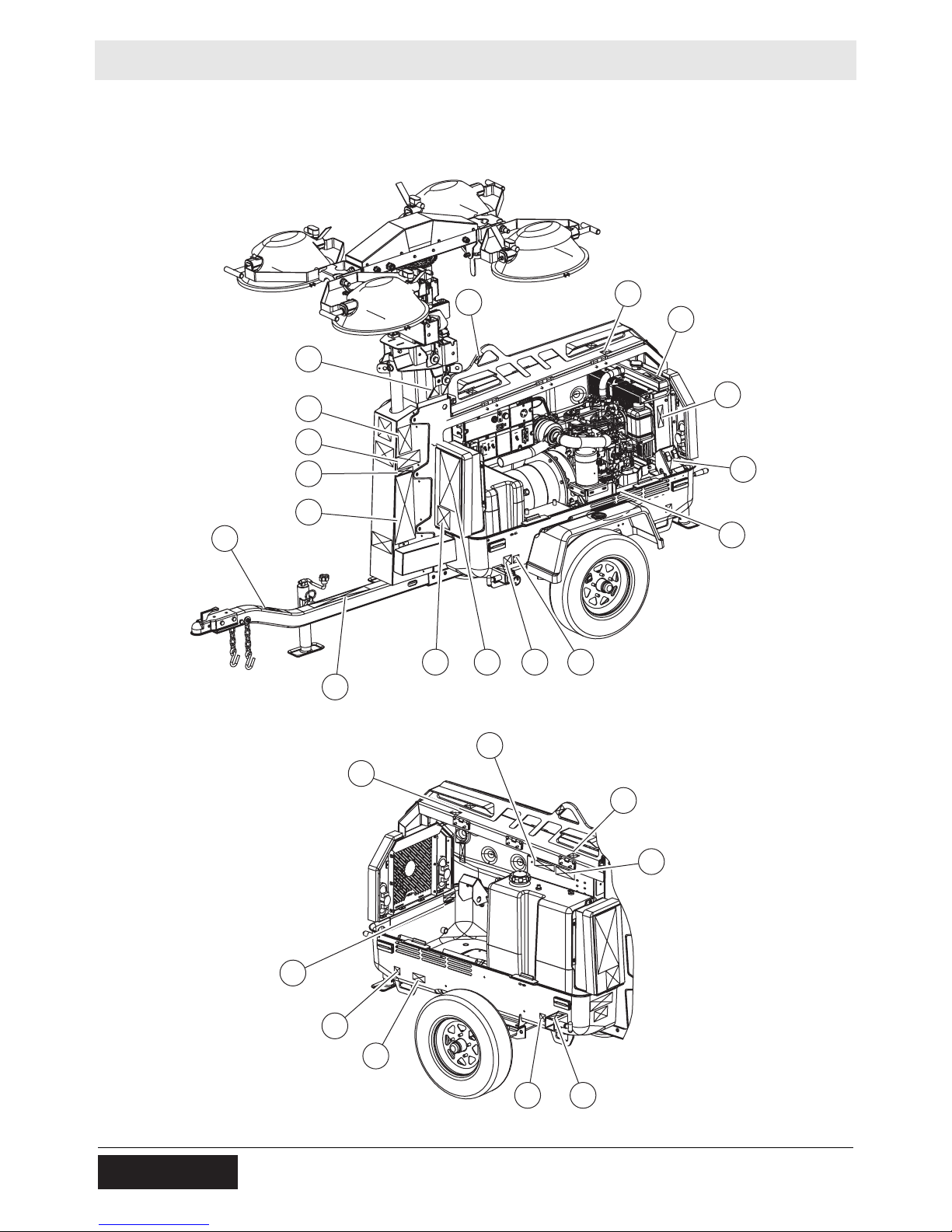
2 Labels
2.1 Label Locations
M
A
Q
P
O
N
B
HIJK
L
C
D
E
F
G
Y
H
C
X
R
C
S
WH
wc_gr009301
20 wc_si000705gb.fm
Page 21
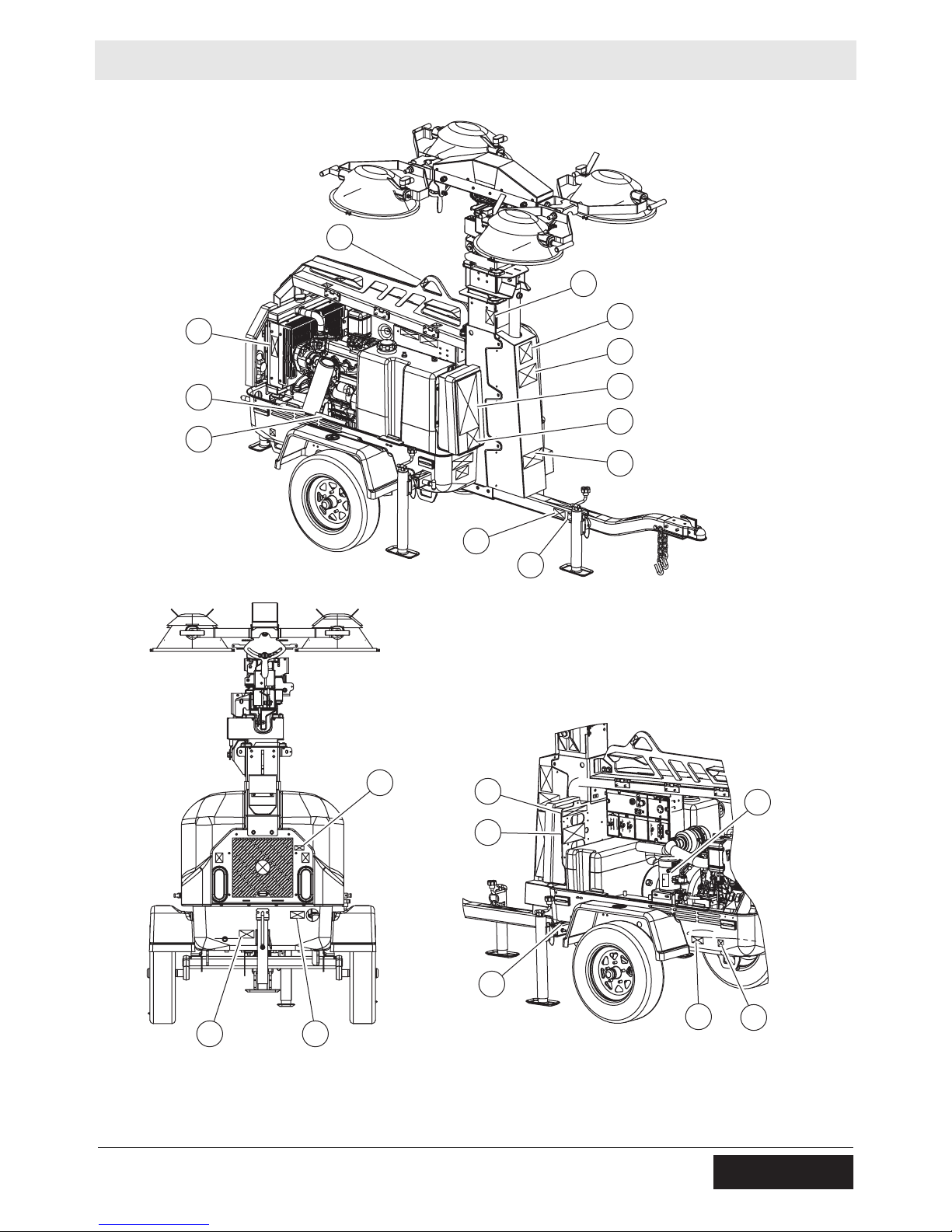
LTN Labels
B
A
E
DD
G
Z
EE
AA
K
BB
CC
W
FFW
wc_si000705gb.fm 21
JJ
GG
HH
W
X
wc_gr009302
II
H
Page 22
Labels LTN
176105
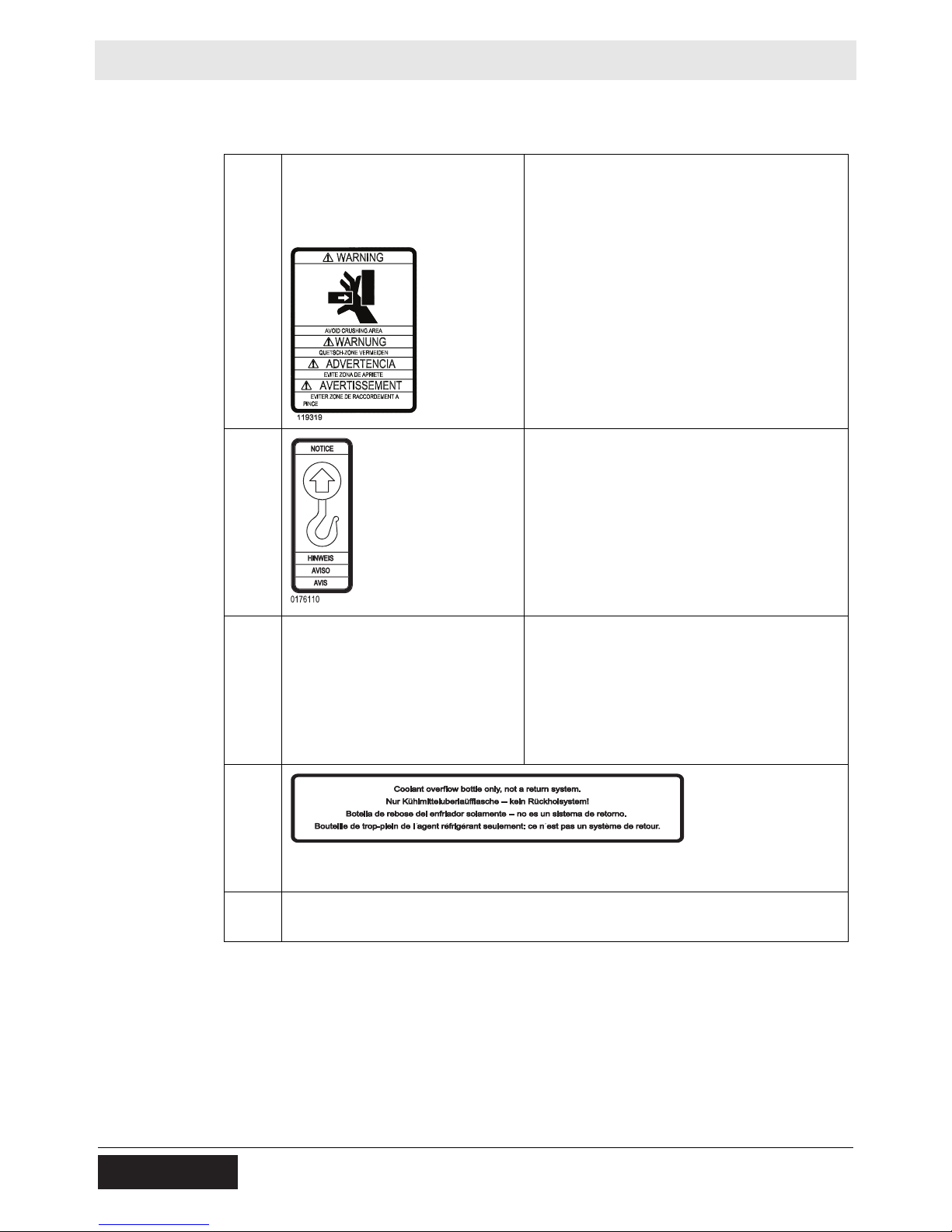
2.2 Label Meanings
A
B
WARNING
Avoid crushing area.
NOTICE
Lifting point
C
D
D
Fork lift pocket
176105
Coolant overflow bottle only, not a return system.
22 wc_si000705gb.fm
Page 23
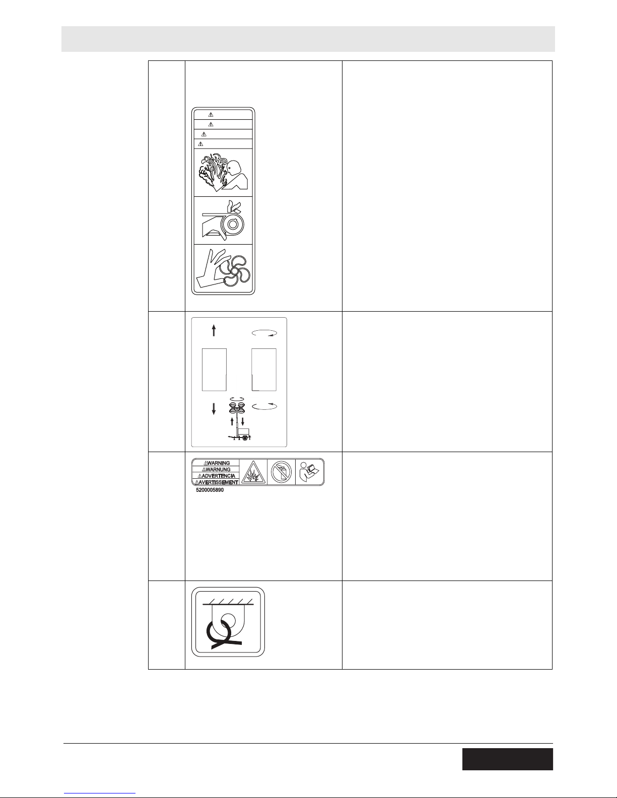
LTN Labels
178775
AVERTISSEMENT
ADVERTENCIA
WARNUNG
WARNING
113726
E
F
ADVERTENCIA
AVERTISSEMENT
178775
WARNING
WARNUNG
WARNING
Pressurized contents. Do not open when hot
Pinching / cutting hazards. Rotating machinery.
Tower and light adjustment switches.
The switch on the left controls the up and
down movement of the tower.
The switch on the right controls the auto-
rotation of the tower (optional).
G
H
WARNING
Explosion hazard. Do not use evaporative
starting fluids such as ether on this engine.
The engine is equipped with a cold starting
aid. Using evaporative starting fluids can
cause an explosion which can cause engine
damage, personal injury , or d eath. Read and
follow the engine starting instructions in this
Operator's Manual.
Tie-down point
113726
wc_si000705gb.fm 23
Page 24
Labels LTN
I
J
Electrical ground
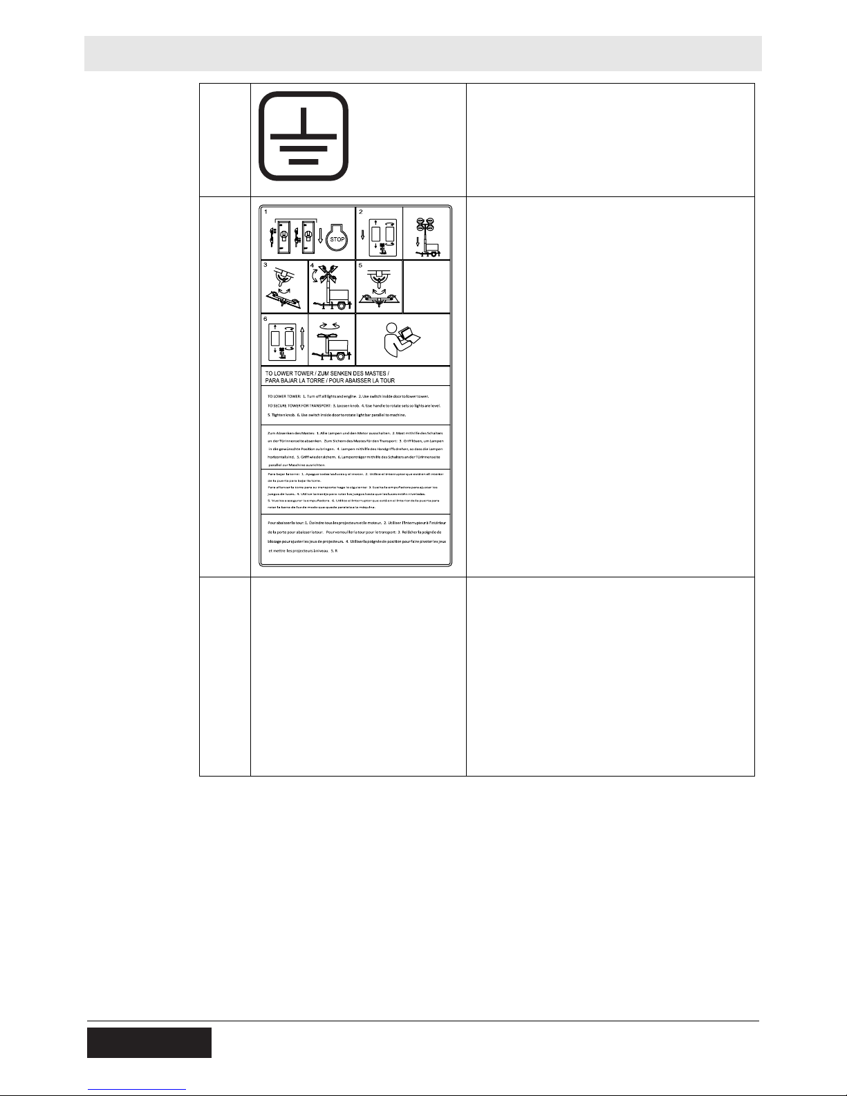
TO LOWER TOWER:
1. Turn off all lights and engine.
2. Use switch inside door to lower tower.
TO SECURE TOWER FOR TRANSPORT:
3. Loosen knob.
4. Use handle to rotate sets so lights are
level.
5. Tighten knob.
6. Use switch inside door to rotate light bar
parallel to machine.
K
WARNING
Electric shock and arc flash can cause serious injury or death. Electrical storage device
within. Contact a qualified electrician for service or to open electrical box.
24 wc_si000705gb.fm
Page 25
LTN Labels
Al remolcar, evite altas
velocidades, aceleracion
rapida, y vueltas agudas.
DANGER DE RETORNEMENT
AVERTISSEMENT
ADVERTENCIA
PELIGRO DE VUELCO
Avoid high speeds, rapid
acceleration and sharp turns
when towing.
WARNING
ROLL OVER HAZARD
178647
En remorquant, éé
viter des
vitesses rapides, acceleration
rapide, et virages tranchantes.
L
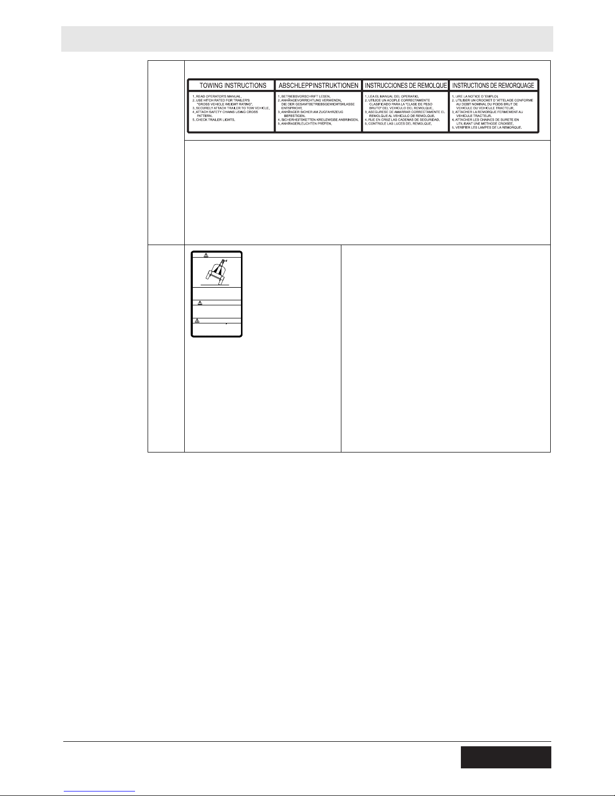
Towing Instructions
Read Operator’s Manual.
Use hitch rated from trailer’s “Gross Vehicle Weight Rating”.
Securely attach trailer to tow vehicle.
Attach safety chains using cross pattern.
Attach breakdown chain to vehicle.
Check trailer lights.
M
BB
WARNING
ROLL OVER HAZARD
Avoid high speeds, rapid
acceleration and sharp turns
when towing.
ADVERTENCIA
PELIGRO DE VUELCO
Al remolcar, evite altas
velocidades, aceleracion
rapida, y vueltas agudas.
AVERTISSEMENT
DANGER DE RETORNEMENT
En remorquant,
vitesses rapides, acceleration
rapide, et virages tranchantes.
178647
WARNING
Roll-over hazard
To prevent injury or equipment damage,
avoid high speeds and sharp turns when
towing.
viter des
wc_si000705gb.fm 25
Page 26
Labels LTN
N
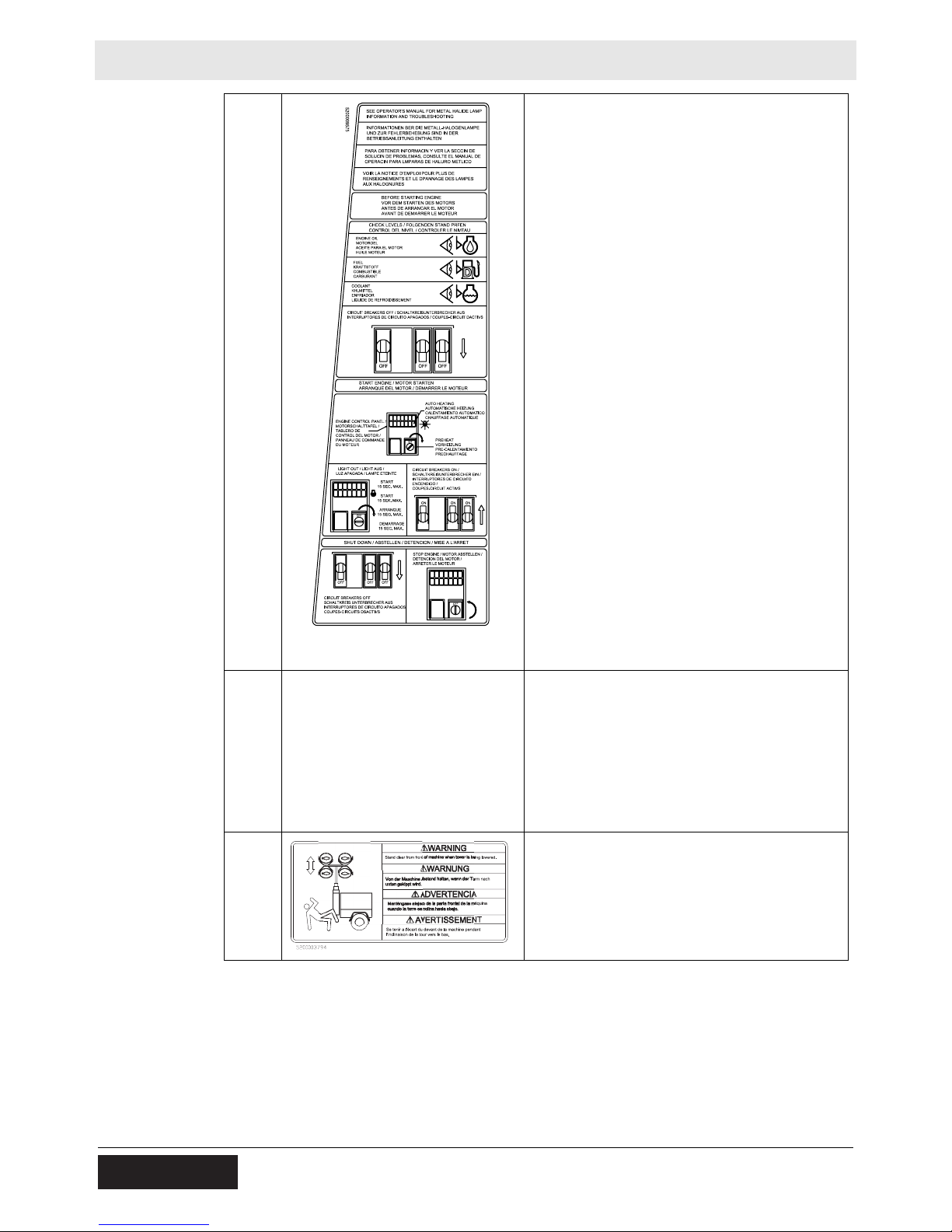
See Operator’s Manual for metal halide lamp
information and troubleshooting.
BEFORE STARTING THE ENGINE:
1. Check levels of
Engine oil
Fuel
Coolant
2. Move the circuit breakers to the OFF
position.
TO START THE ENGINE:
1. On the engine control panel, turn the key
switch to the PREHEAT position; the
indicator light will illuminate during
preheating.
2. When the PREHEAT indicator light goes
out, turn the key switch to the START
position for a maximum of 15 seconds.
3. When the engine is running, move the
circuit breakers to the ON position.
TO SHUT DOWN THE MACHINE:
Move the circuit breakers to the OFF
position.
Turn the key switch to the OFF
position to stop the engine.
O
P
WARNING
Operation of this equipment may create
sparks that can start fires around dry vegetation. A spark arrester may be required. The
operator should contact local fire agencies
for laws or regulations relating to fire prevention requirements.
WARNING
Crushing hazards.
Stand clear of front and rear of machine
when tower is being raised or lowered.
26 wc_si000705gb.fm
Page 27
LTN Labels
Q
R
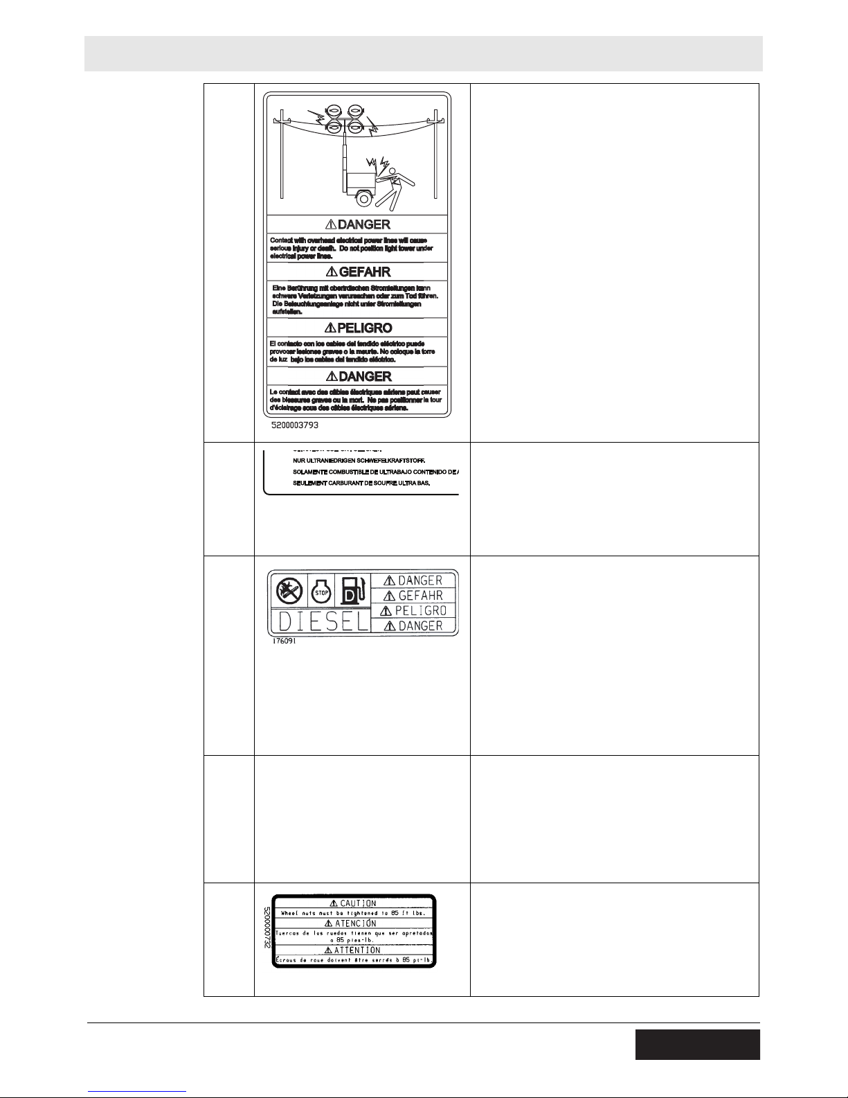
DANGER
Contact with overhead electrical power lines
will cause serious injury or death. Do not
position Light Tower under electrical power
lines.
Low sulfur fuel or ultra low sulfur fuel only.
S
W
X
DANGER
No sparks, flames, or burning objects near
machine. Stop the engine before adding fuel.
Use only diesel fuel.
Insert jack locking pin before extending jack.
CAUTION
Wheel nuts must be tightened to 85 ft.lbs.
wc_si000705gb.fm 27
Page 28
Labels LTN
UTILITY 159116
U.S.PAT.Nos.: 6012285, 6471476,
D416858, D454357 OTHER U.S. AND
FOREIGN PATENTS PENDING
Y
Z
AA
U.S.PAT.Nos.: 6012285, 6471476,
D416858, D454357 OTHER U.S. AND
FOREIGN PATENTS PENDING
UTILITY 159116
This machine may be covered by one or
more patents.
Read and understand the supplied Operator’s Manual before operating the machine.
Failure to do so increases the risk of injury to
yourself and others.
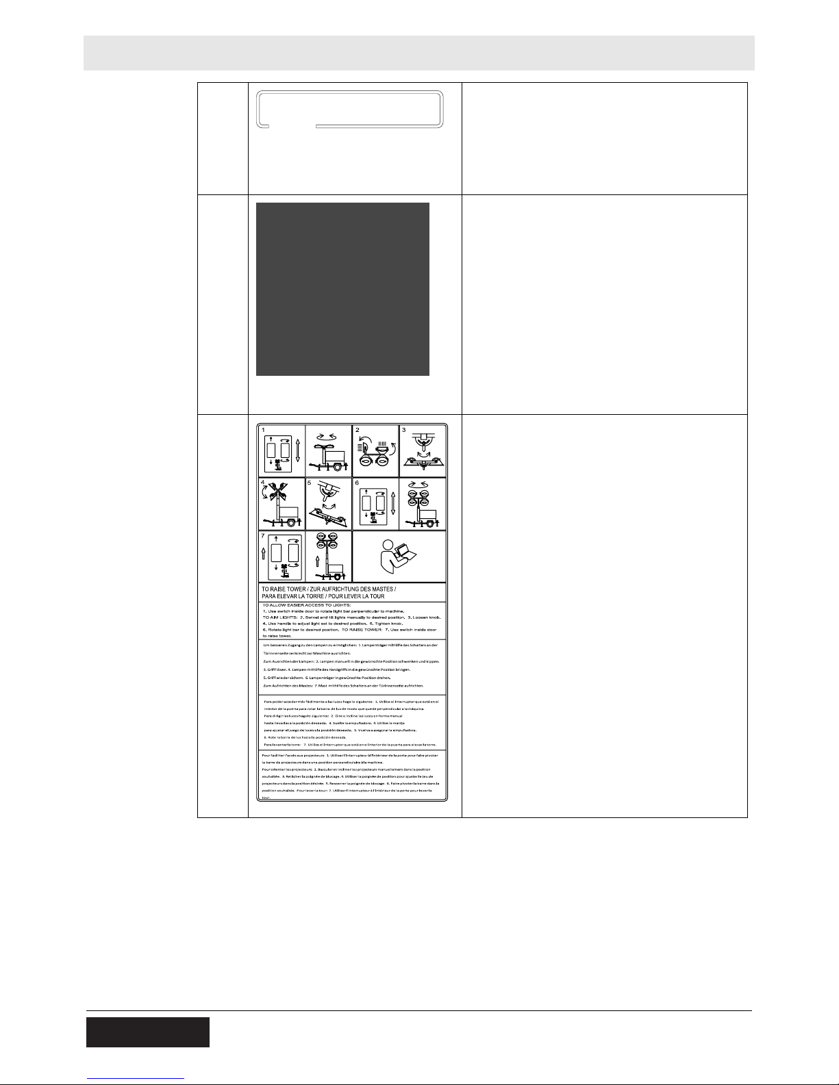
TO RAISE TOWER
TO ALLOW EASIER ACCESS TO LIGHTS:
1. Use switch inside door to rotate light bar
perpendicular to machine.
TO AIM LIGHTS:
2. Swivel and tilt lights manually to desired
position.
3. Loosen knob.
4. Use handle to adjust light set to desired
position.
5. Tighten knob.
6. Rotate light bar to desired position.
TO RAISE TOWER:
7. Use switch inside door to raise tower.
28 wc_si000705gb.fm
Page 29

LTN Labels
179213
WARNUNG
ADVERTENCIA
WARNING
AVERTISSEMENT
117037
CC
DD
EE
Transport position of the jack
179213
WARNING
Hot surface
WARNING
Ultraviolet radiation from lamp can cause
serious skin and eye irritation. Use only with
undamaged lamps. Use only with provided
undamaged lens cover and fixture.
FF
GG
HH
GG
HH
WARNING
WARNUNG
ADVERTENCIA
AVERTISSEMENT
117037
DANGER
Using a light tower indoors CAN KILL YOU IN MINUTES. Light tower exhaust
contains carbon monoxide. This is a poison you cannot see or smell.
NEVER use inside a home or garage, EVEN IF doors and windows are open.
WARNING
Hot surface
Only use OUTSIDE and far away from windows, doors, and vents.
wc_si000705gb.fm 29
Page 30
Labels LTN
117039
ADVERTENCIA
AVERTISSEMENT
WARNING
WARNUNG
II
JJ
117039
WARNING
WARNUNG
ADVERTENCIA
AVERTISSEMENT
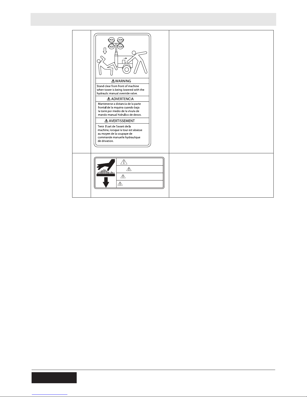
WARNING
Crushing hazards.
Stand clear of the front of the machine when
the tower is being lowered with the hydraulic
manual override valve.
WARNING
Hot surface
30 wc_si000705gb.fm
Page 31

LTN Lifting and Transporting
3 Lifting and Transporting
3.1 Lifting the Machine
Requirements
Procedure
Properly rated lifting equipment (crane or hoist). See Chapter Technical Data.
Machine stopped. See topic Stopping the Machine.
All doors and access covers closed and secured.
Tower is completely lowered.
Lights have been rotated so that they are level with the ground.
Outriggers have been returned to their travel position.
Outrigger bars and jacks are locked in place.
Tongue jack (c) is completely cranked in and rotated 90°.
WARNING
Crushing hazard. You may be crushed if the lifting devices fail.
f Never stand under, or get onto, the machine while it is being lifted or moved.
f Use only the designated lifting points to lift the machine.
Follow the procedure below to lift the machine.
1. Attach the lifting equipment to one of the lifting eyes (b) on the machine using
hooks, shackles, and chains or insert forks into the fork pockets (a).
a ab
c
wc_gr009966
2. Lift the machine a small distance.
WARNING
Crushing hazard. An unstable machine may cause the lifting devices to fail. You
may be crushed if the lifting devices fail.
f Check for stability before continuing.
3. Check for stability. If necessary, lower the machine, reposition the lifting device,
and lift the machine a small distance again.
4. Continue lifting the machine as necessary.
wc_tx003095gb.fm
31
Page 32

Lifting and Transporting LTN
3.2 Preparing the Machine for Transport on a Truck or Trailer
Requirements
Checklist
Machine stopped.
Flatbed truck or trailer capable of supporting the machine’s weight.
Chains, hooks, or straps capable of supporting the machine’s weight.
WARNING
Crushing hazard. Improperly securing the machine can lead to a crushing hazard.
f Use only the designated tie-down points to secure the machine to a truck or
trailer.
Before transporting the machine, check the following items:
Machine
Check that all doors and access panels of the machine are closed.
Check that all electrical supplies are disconnected from the machine.
Check that the generator is shut down.
Check that the tower is completely lowered.
Check that the outriggers are in the travel position.
Check that the outrigger bars and jacks are locked in place.
Check that the tongue jack is in the travel position.
Check that the the lights are rotated so they are level with the ground.
Loading and transporting equipment
Check that th e transport vehicle or trailer can support the weigh t of the machine.
Check that the wheels of the transport vehicle or trailer are chocked during the
loading process.
Check that the transport vehicle or trailer is clean and free of grease, oil, ice,
and other loose material.
Do not use the machine’s trailer jack to support the trailer tongue during
transporting.
Check that any ramps used in the loading process:
Can support the weight of the machine
Are clean and free of grease, oil, ice, and other loose material.
Are securely connected to the transport vehicle or trailer.
Are of sufficient length to keep the loading angle 15° or less.
In addition:
Check that the loading area is flat and the ground is stable.
Check the overall height of the machine once loaded. Plan your travel route so
there will be adequate clearance for overpasses, road signs, buildings, etc.
Check local regulations regarding transporting and obey these regulations.
32
wc_tx003095gb.fm
Page 33

LTN Lifting and Transporting
3.3 Preparing the Machine for Towing
Before towing the machine, check the licensing requirements for trailers in your
area. Also check the following items:
Machine
Check that all doors and access panels of the machine are closed.
Check that all electrical supplies are disconnected from the machine.
Check that the generator is shut down.
Check that the tower is completely lowered.
Check that the outriggers are in the travel position.
Check that the outrigger bars and jacks are locked in place.
Check that the tongue jack is in the travel position.
Check that the lights are rotated so they are level with the ground.
Hitch and coupler
Check that the towing vehicle and hitch have a rating equal to or greater than
the GVWR of the machine. See Technical Data.
Check that the hitch of the towing vehicle and coupler of the trailer are
compatible.
Check the condition of both the coupler and the hitch.
Check that all fasteners on the coupler are secure.
Check that the coupler has fresh grease applied to it.
Wheels
Check that all lug nuts are in place and are properly torqued.
Check the tread wear of the tires.
Check that the tires are inflated to the proper pressure.
Trailer operation
Check that the directional and running lights on the trailer function correctly.
Check that the safety chains of the trailer are connected to the towing vehicle
using a crisscross pattern.
Check that the trailer’s breakaway cable is attached to the towing vehicle.
Check th e operation of the trailer brake s by braking the towing vehicle at a slow
speed.
wc_tx003095gb.fm
33
Page 34

Lifting and Transporting LTN
3.4 Towing the Machine
WARNING
Risk of severe injury or death. Improperly torqued lug nuts can lead to loss of
wheels. Loss of wheels can cause an accident, severe injury or death.
f Tighten the lug nuts to the proper torque before towing the machine.
NOTICE: Wacker Neuson recommends a maximum towing speed of 88km/h
(55mph) on highways and paved roads and 16km/h (10mph) on rugged roads an d
terrain.
Procedure
Perform the procedure below when towing the machine.
1. Read and follow the towing safety guidelines. See topic Safety Guidelines for
Towing the Machine.
2. Complete the shut-down procedures.
3. Adjust the amount of fuel in the machine to approximately 70% cap acity to avoid
fuel spillage.
4. Complete the Before Towing Checklist. See topic Before Towing Checklist.
5. Connect the machine to the towing vehicle.
6. Rotate the trailer and tongue jacks to a horizontal position.
7. Tow the machine as needed.
34
wc_tx003095gb.fm
Page 35

LTN Operation
4 Operation
4.1 Preparing the Machine for First Use
1. Make sure all loose packaging materials have been removed from the machine.
2. Check the machine and its components for damage. If there is visible damage,
do not operate the machine! Contact your Wacker Neuson dealer immediately
for assistance.
3. Take inventory of all items included with the machine and verify that all loose
components and fasteners are accounted for.
4. Attach component parts not already attached.
5. Add fluids as needed and applicable, including fuel, engine oil, and battery acid.
6. Move the machine to its operating location.
4.2 Generator Derating
Description
Derating
percentages
All generator sets are subject to derating (reduced power output) depending on the
altitude and ambient temperature. Derating should not affect the operation of the
floodlights, although it will reduce the available reserve power to the receptacle.
Power ratings are typically reduced by the following percentages:
3% per 300 m (1000 ft.) elevation above sea level
2% per 5.5°C (10°F) increase in ambient temperature above 25°C (78°F).
wc_tx003098gb.fm
35
Page 36

Operation LTN
4.3 Positioning the Machine
DANGER
Asphyxiation hazard. Exhaust gas from the machine contains carbon monoxide, a
deadly poison you cannot see or smell. Exposure to carbon monoxide can kill you
in minutes.
f Position the machine so that exhaust will not enter any nearby structures.
WARNING
Fire hazard. Do not move the machine while it is running.
f Shut down the machine before moving or repositioning it.
WARNING
Electric shock hazard. The tower extends up to 9 m (30 ft.) and could contact
overhead wires or obstructions.
f
Position the trailer on a firm, flat surface clear of overhead wires and obstructions.
CO Alarms
Requirements
WARNING
Fire hazard. Machines positioned on a hill or an incline may slide, break away or
roll over.
f Do not position the machine on a hill or an incline.
WARNING
Explosion and fire hazard. Risk of severe injury or death.
f Do not operate the machine near flammable vapors, fuels, or combustibles.
Because this machine produces carbon monoxide (CO), Wacker Neuson
recommends that CO alarms be installed in all structures in close proximity to the
machine. CO alarms provide an extra measure of protection against this poison
that you cannot see or smell.
Install battery-operated CO alarms or plug-in CO alarms with battery backup,
according to the manufacturer’s instructions. CO alarms should be certified to the
requirements of the latest safety standards (UL 2034, IAS 6-96, or CSA 6.19.01).
Test the CO alarm batteries monthly.
Position the machine:
so that machine exhaust will not enter nearby structures.
so that the machine does not block traffic.
so that the machine is not near any combustible material or flammable vapor.
so that all of the machine’s access doors/panels may be accessed.
so that the area to be illuminated is at or below the level of the lights.
so that there is room around the machine for the outriggers to be extended.
36
wc_tx003098gb.fm
Page 37

LTN Operation
4.4 Ground Connection
A ground connection (a) is located on the trailer frame.
a
wc_gr010503
Function
This ground connection is used for electrically grounding the Light Tower when
necessary to comply with the National Electrical Code and other federal, state, and
local regulations. For grounding requirements in you r area, consult with a qualified
electrician, electrical inspector, or local agency having jurisdiction over electrical
compliance.
If the Light Tower is used at a construction site, there may be additional
regulations which must be observed.
wc_tx003098gb.fm
37
Page 38

Operation LTN
4.5 Leveling Trailer
WARNING
Tipping and falling hazard. Failure to level the trailer or extend the outriggers will
severly reduce the stability of the unit.
f Level the trailer and extend the outriggers before raising the tower. The outrig-
gers must remain extended while the tower is up.
Procedure
Perform the procedure below to level the trailer.
1. Pull the locking pin on the tongue jack (a) and rotate the tongue jack down 90°
as shown. Reinsert the pin once the jack is in position.
e c d
f
b
2. Block or chock the trailer wheels (b).
3. Crank the tongue jack (a) down to raise the trailer tongue off the vehicle.
4. Pull the outrigger lock pins (c) to release the outriggers. Pull both outrig gers (d)
out until you feel lock pin snap into place.
5. Pull the locking pins on the outrigger jacks (e). Rotate the jacks 90° down.
Reinsert the pins once the jacks are in position.
a
wc_gr009972
6. Pull the locking pin on the rear jack (f) and rotate the rear jack down 90°.
Reinsert the pin once the jack is in position.
7. Extend the jack(s) on the highest side(s) of the trailer until they rest firmly on the
ground. Extend the remaining jacks until the trailer is level.
38
wc_tx003098gb.fm
Page 39

LTN Operation
4.6 Refueling the Machine
Requirements
Procedure
Machine shut down
Engine cool
Machine/fuel tank level with the ground
Fresh, clean fuel supply
Perform the procedure below to refuel the machine.
WARNING
Fire hazard. Fuel and its vapors are extremely flammable. Burning fuel can cause
severe burns.
f Keep all sources of ignition away from the machine while refueling.
f Refuel only when the machine is outdoors.
f Clean up spilled fuel immediately.
1. Remove the fuel cap (a).
a
Result
D
wc_gr008825
2. Fill the fuel tank, allowing a minimum of 50 mm (2 in.) exp ansion space b etween
the fuel level and the top of the tank.
CAUTION
Fire and health hazard. Fuel expands when heated. Expanding fuel in an over-filled
tank can lead to spills and leaks.
f Do not fill the fuel tank completely.
3. Reinstall the fuel cap.
The procedure to refuel the machine is now complete.
wc_tx003098gb.fm
39
Page 40

Operation LTN
4.7 Aiming the Lights - LTN-V
Overview
Requirements
Aiming the
light fixtures
Each individual light fixture can be aimed up, down, left, or right independent of
one another. There are four total light fixtures on each machine.
The light bars, which include two light fixtures each, can be tilted 45° in each
direction from horizontal.
This procedure is not for rotating the lights as a single unit while the tower is
raised. This procedure requires the tower is lowered and the is machine
stopped. To rotate the lights, see topic Rotating the Lights.
Before adjusting the lights, make sure that the following conditions have been met.
Machine is stopped
Tower is completely lowered
Lights are cool to the touch
Aiming Up or Down
Perform the procedure below to aim an individual light fixture up or down.
1. Loosen the T-handle (a) and aim the light up or down.
NOTICE: Do not loosen the nut (b). Damage to the light fixture may occur.
a
a a
b
2. Tighten the T-handle (a) when the light is aimed properly.
3. Repeat steps 1—3 for each remaining light fixture, if desired.
This procedure continues on the next page.
wc_gr009317
40
wc_tx003098gb.fm
Page 41

LTN Operation
Continued from the previous page.
Aiming Left or Right
1. Grasp the light fixture and aim it to the light lef t or right. If necessary, loosen the
bracket nut (c) to allow movement of the fixture.
NOTICE: Do not loosen the nut (b). Damage to the light fixture may occur.
c c
b
c
wc_gr010507
2. If loosened, tighten the bracket nut (c) when the light is aimed properly.
Note: The bracket nut (c) should be only tight enough so that slight resistance is
present when aiming the fixture.
3. Repeat steps 1—2 for each remaining light fixture, if desired.
This procedure continues on the next page.
wc_tx003098gb.fm
41
Page 42

Operation LTN
Continued from the previous page.
Aiming the
light bars
Perform the procedure below to aim the light bars.
1. Loosen the knob (d), grasp the handles (e), and tilt the light bar to the desired
angle.
2. Tighten the knob (d) when the light bar is in the desired position.
3. Repeat steps 1—2 for the other light bar, if desired.
42
wc_tx003098gb.fm
Page 43

LTN Operation
4.8 Control Panels
l fl f gk k gh
1
6K 8K
ea
bb c d c dc d
2
Ref Description Ref Description
Floodlight control panel
1
Tower control panel
2
25A main circuit breaker
a
30A lights circuit breaker
b
20A GFI circuit breaker
c
20A GFI receptacle
d
33A main circuit breaker
e
Hour meter
f
30A receptacle
g
30A receptacle breaker
h
Tower actuation switch
i
Tower rotation switch
j
Glow plug indicator
k
Key switch
l
ji
wc_gr009973
wc_tx003098gb.fm
43
Page 44

Operation LTN
KOHLER
4.9 Control Panels - LTN 6L-VS
12
e
f
o
p
a
b
c d
h k
g
KOHLER
m
l
n
q
wc_gr005141
1: Floodlight Control Panel
2: Engine Control Panel
Ref. Description Ref. Description
a 50 Amp circuit breaker k High coolant temperature shut-
down indicator
b 30 Amp lights circuit breaker l Alternator indicator
c 20 Amp circuit breaker m Auxiliary lights (not used)
d 20 Amp GFI receptacle n Glow plug indicator
e Hour meter o Air filter restriction indicator
f Low fuel indicator (not used) p Auxiliary lights (not used)
g Safety shutdown indicator q Key access door
h Low oil pressure shutdown indi-
cator
r GFCI circuit breaker
wc_tx003098gb.fm
44
Page 45

LTN Operation
4.10 Befo re Starting
Before putting the Light Tower into service, review each item on the following
checklist. Light Towers often run unattended for long periods of time. Therefore, it
is important to make sure that the machine is set up properly to avoid possible
operating problems.
CAUTION
Improper machine setup may cause injury or equipment damage.
f Perform all pre-start checks listed below. Do not operate the machine until all
items on the checklist have been addressed.
Check
machine
condition
Check the
engine
Review safety
information
Verify that the machine is level and positioned on a stable surface.
Perform a walk-around to check for visible damage.
Inspect the lights and lamps: ensure that glass is not broken or cracked.
Ensure that all electrical connections are tight.
Verify that all electrical cords are in serviceable condition with no exposed wires,
cuts, or cracks in the insulation.
Close and secure access covers before starting the machine.
Check fuel, engine oil, and coolant levels. Add fluids if necessary.
Verify that the air filter element is clean and undamaged. Replace if necessary.
Check to make sure no debris has lodged in vents, near the radiator, or around
the fan.
Check to make sure that the exhaust compartment is clean and nothing is
touching the muffler or exhaust pipes.
Check fan belt and hose s on engine for loose connections or fraying. T ighten or
replace as required.
Review and follow instructions provided in the “Safety Information” chapter at
the beginning of this Operator’s Manual.
wc_tx003098gb.fm
45
Page 46

Operation LTN
4.11 Starting the Machine - L TN 6K-V, LTN 8K-V
Requirements
NOTICES
Procedure
Before starting checks completed. See Before Starting
Do not use evaporative starting fluids (for example, ether) to start the engine.
Do not start the engine under load.
q n
OFF
GL
Perform the procedure below to start the machine.
1. Rotate the key (q) counter-clockwise to the glow plug position (GL).
The glow plug indicator (n) will illuminate.
The glow plug indicator will turn off when the engine is preheated.
ON
ST
a c
b
wc_gr009978
NOTICE: Cranking the engine longer than 20 seconds could cause damage.
f If the engine does not start, return the key to the “OFF” position and wait 1
minute for the starter to cool before proceding.
2. Immediately rotate and hold the key to the start (ST) position until the engine
starts then release the key.
3. Allow the engine to warm up before operating the lights.
Note: If the oil does not reach operating pressure within 30 seconds, the engine
will stop. You must retu rn the key to the “OFF” for 30 seconds before rest arting the
engine.
46
wc_tx003098gb.fm
Page 47

LTN Operation
4.12 Starting the Machine - LTN 6L
Pre-start
checklist
NOTICES
Check the following items before starting the machine.
Engine oil, fuel and coolant are filled to the proper levels.
Electrical cables in good condition with no cuts or abrasions in the insulation.
Circuit breakers (a, b, c) are in their “OFF” positions.
All loads are disconnected from the machine.
Do not use evaporative starting fluids (i.e., ether) to start the engine.
Do not start the engine under load.
If the fuel tank was empty, you many need to bleed the fuel lines. Refer to the
engine manufacturer’s documentation.
n
a
b
c
q
Procedure
wc_gr011147
Follow the procedure below to start the machine.
1. Rotate the starting key (q) one click to the right.
The glow plug indicator (n) will illuminate.
The glow plug indicator will turn off when the engine is preheated.
2. Immediately rotate and hold the starting key to the “START” position until the
engine starts, then release the key.
NOTICE: Cranking the engine longer than 20 seconds can cause damage. If the
engine does not start, return the starting key to the “OFF” position and wait 1
minute for the starter motor to cool before proceeding.
3. Allow the engine to warm up before operating the lights.
Note: If the oil does not reach operating pressure within 30 seconds, the engine
will stop. You must return the starting key to the “OFF” position for 30 seconds
before restarting the engine.
wc_tx003098gb.fm
47
Page 48

Operation LTN
4.13 Operating the Lights
Requirements
Procedure
Notes
All items in “Before Starting” checklist have been checked
Tower is raised to the desired height
Engine is running and has warmed up
Perform the procedure below to operate the lights.
1. Turn on the main circuit breaker (a).
a b
wc_gr009327
2. Turn on individual circuit breakers (b) one at a time.
Metal halide floodlights require a warm-up time of 5–15 minutes before they
reach full brightness.
After turning the lights off, a cool-down time of 10 minutes is necessary before
they can be turned on again.
48
wc_tx003098gb.fm
Page 49

LTN Operation
4.14 Raising the Tower - LTN -V
Overview
Procedure
The tower is raised by the action of a hydraulic cylinder (c).
Note: The tower can be raised without running the engine.
WARNING
Personal injury hazard. Raising or lowering the tower creates situations that if not
avoided, will cause death or serious injury from striking, crushing, pinching,
electrocution, etc.
f Keep the area under and around the lights clear of people and obstructions
while raising and lowering the tower.
Perform the procedure below to raise the tower.
1. If equipped, engage the parking brake on the trailer.
Note: The tower will not raise if the brake is not engaged.
2. Aim the lights. See topic Aiming the Lights.
3. Start the engine. See topic Starting the Machine.
4. Turn on the circuit breakers (a,b). See topic Operating the Lights.
c
5. Press and hold the upper half of the tower switch (d). Release the switch when
the tower reaches the desired height. See topic Rotating the Mast for more
information.
a b d e
wc_gr009319
wc_tx003098gb.fm
49
Page 50

Operation LTN
4.15 Manually Rotating the Mast
Overview
Procedure
The operator can rotate the mast 360° while the tower is lowered.
To rotate the mast, perform the procedure below.
1. Pull out the locking pin (a) on the bottom of the mast.
2. Rotate the mast to the desired position.
3. Engage the locking pin (a).
Note: Be sure the locking pin seats into a groove on the sprocket.
50
wc_tx003098gb.fm
Page 51

LTN Operation
4.16 Lowering the Tower
Overview
Notes
Procedure
A low-voltage electrical circuit controls the release of pressure in the hydraulic
cylinder (c). When pressure is released, the tower will lower.
The engine does not need to be running to lower the tower.
The hydraulic circuit includes a pressure release valve that lowers the tower in
an emergency situation. See topic Emergency Shutdown Procedure.
If the parking brake on the trailer is disengaged while the tower is raised, it will
lower automatically.
WARNING
Personal injury hazard. Raising or lowering the tower creates situations that if not
avoided, will cause death or serious injury from striking, crushing, pinching,
electrocution, etc.
f Keep the area under and around the lights clear of people and obstructions
while raising and lowering the tower.
Perform the procedure below to lower the tower.
1. Stop the engine.
2. Turn off the circuit breakers (a, b).
wc_tx003098gb.fm
c
a b d
wc_gr009321
3. Press and hold the lower half of the tower switch (d). Release the switch when
the tower is completely lowered.
51
Page 52

Operation LTN
4.17 Automatic Shutdown
Description
This machine is equipped with a low oil, high temperature automatic shutdown
system. This system will automatically interrupt the fuel supply to the engine if the
oil pressure drops too low or the engine exceeds normal operating temperatures.
Resetting
after
If an automatic shutdown occurs, the engine will stop. Return the key switch to the
off position to reset the system.
automatic
shutdown
See Troubleshooting or contact Wacker Neuson Product Support if automatic
shutdown frequently occurs.
4.18 Stopping the Machine - LTN 6K/8K-V
NOTICE: Turn off the lights before stopping the engine. Failure to do so will
damage the electrical system.
Procedure
Perform the procedure below to stop the machine.
1. Disconnect all loads from the machine.
2. Turn the circuit breakers (a, b, c) off.
OFF
GL
ON
ST
3. Rotate the key to the “OFF” position.
q n
a
b
c
wc_gr009978
52
wc_tx003098gb.fm
Page 53

LTN Operation
4.19 Stopping the Machine - LTN 6L-V
NOTICE: Do not stop the machine without turning off the lights. Damage to the
electrical generator will occur.
Procedure
Follow the procedure below to stop the machine.
1. Remove all connected loads from the machine.
2. Turn the circuit breakers (a, b, c) off.
230VAC
q
b ca
wc_gr009360
3. Rotate the starting key (q) to the “OFF” position.
wc_tx003098gb.fm
53
Page 54

Operation LTN
4.20 Emergency Shutdown Procedure
General
procedures
Hydraulic
release valve
If a breakdown or accident occurs while the machine is operating, follow the
procedure below:
1. Stop the engine.
2. Disconnect all loads from the machine.
3. Lower the tower.
4. Allow the machine to cool before opening the cabinet.
5. Contact the rental yard or machine owner for further instructions.
The hydraulic pump (b) is equipped with a pressure release valve (c). This valve
enables the tower to be lowered manually.
If electrical power is lost, or the tower switch is inoperable, pull the knob on the
pressure release valve. The hydraulic cylinder will retract and the tower will
lower. Push the knob to close the valve after the tower is fully lowered.
WARNING
Personal injury hazard. Raising or lowering the tower creates situations that if not
avoided, will cause death or serious injury from striking, crushing, pinching,
electrocution, etc.
f Keep the area under and around the lights clear of people and obstructions
while raising and lowering the tower.
wc_gr009980
wc_tx003098gb.fm
54
Page 55

LTN Operation
CONDUCTOR NEUTRO
CONECTADO AL CHASIS
NULL-LEITER AM RAHMEN
ANGESCHLOSSEN
NEUTRAL BONDED TO FRAME
CONDUCTEUR NEUTRE MIS
A LA MASSE DU CHASSIS
ADVERTENCIA
AVERTISSEMENT
WARNING
WARNUNG
4.21 Using the Convenience Receptacles - 60 Hz
Description
Mandates
This machine is equipped with one or more convenience receptacles (b) for
running accessories and tools from the generator. Each receptacle is protected by
its own circuit breaker (a). Power to the receptacle(s) is available any time the
engine is running and the circuit breaker is set to the ON position.
a b
WARNING
WARNUNG
ADVERTENCIA
AVERTISSEMENT
NEUTRAL BONDED TO FRAME
NULL-LEITER AM RAHMEN
ANGESCHLOSSEN
CONDUCTOR NEUTRO
CONECTADO AL CHASIS
CONDUCTEUR NEUTRE MIS
A LA MASSE DU CHASSIS
wc_gr011034
Obey the mandates below to avoid damaging the machine, accessories, or tools.
Do not use frayed or damaged cords or plugs with the convenience receptacle.
The maximum wattage (with the lights on) drawn from the recptacles shall not
exceed the values below.
LTN 6:1660W
LTN 8: 3660W
Use only tough rubber-sheathed flexible cable or equivalent. (per 1EC245-4).
When using extension cords or mobile distribution networks, the total length of
cords should not exceed the values below.
16 gauge: 60 m (197 ft.)
13 gauge: 100 m (328 ft.)
This machine generates increased voltage while the lights are reaching full
brightness. To avoid damaging sensitive electronic equipment, do not connect
any such devices to the convenience outlet until the machine and lights have
been operating for at least ten minutes.
Each 120V GFI receptacle (b) is protected by a 20A circuit breaker (a).
Testing a GFI
Before each use, perform the procedure below to test a GFI receptacle.
receptacle
1. Push the test button in.
The reset button should pop out.
Power to the receptacle is now off.
2. Push the reset button in.
NOTICE: If the reset button does not pop out, the GFI is defective. Do not use the
receptacle until the problem is corrected.
wc_tx003098gb.fm
55
Page 56

Factory-Installed Options LTN
5 Factory-Installed Options
This machine may be equipped with one or more of the following factory-installed
options. To verify if any of these options are installed on your machine, contact
Wacker Neuson Corporation at 1-800-770-0957. A nameplate listing the Model
Number, Item Number, Revision, and Serial Number is attached to each unit.
Please have this information available when contacting Wa cker Neuson
Corporation.
The illustrations shown in this chapter represent typical installations. The factoryinstalled options on your machine may look different.
5.1 E ngine Block Heater
The engine block heater includes a block heater (a) with a cord (b). The function of
the block heater is to heat the engine coolant/ engine block to improve coldweather engine starting. Plug the cord into a 120V power supply.
5.2 Battery Blanket
An electrically powered blanket (a) warms the battery while the machine is not in
use. The blanket eliminates engine starting difficulties caused by a cold or frozen
battery. Plug the cord into a 120V power supply.
a
b
wc_gr006975
a
wc_gr007422
56 wc_tx001650gb.fm
Page 57

LTN Factory-Installed Options
5.3 Oil Pan Heater
Cold, thick engine oil does not flow freely and may cause engine starting
difficulties. An oil pan heater installed on the engine oil pan keep s the oil warm and
flowing. Heat from this electrical device warms the supply of engine oil contained in
the pan while the machine is not in use. Plug the cord into a 120V power supply.
5.4 RCBO Circuit Breaker
Available for 50 Hz machines is an Residual Current Circuit Breaker with
Overcurrent Protection (RCBO). On these machines, the RCBO takes the place of
the standard receptacle circuit breaker. Machines with RCBOs have neutral
bonded to ground and thus these machines require grounding.
The RCBO functions as an overcurrent protection device and a current leakage
detection device.
Whenever an overcurrent condition or a current leakage condition exists, the
RCBO’s activation lever springs to the OFF position. This opens the circuit. If the
activation lever springs to the OFF position during use, there is a problem. Do not
use the receptacle until the problem is corrected.
a
b
wc_gr011379
Test the RCBO every 6 months.
Note: The RCBO must be connected and the main circuit breaker must be in the
ON position when testing.
To test:
1. Set the activation lever (a) to the ON position.
2. Press the “TEST” button (b). The activation lever must spring to the OFF
position. If it does not, the RCBO has failed. Replace it.
wc_tx001650gb.fm 57
Page 58

Factory-Installed Options LTN
5.5 L ED Lights
The LED light option includes 4 X 320 Watt LED fixtures that require less than 1
second warm-up time, no maintenace, and 100-264 VAC. The LED fixtures are
rated for use in extreme cold temperatures to -40° F and offer voltage and current
protection. This feature is offered as a retrofit kit or as a factory-installed option.
wc_gr011912
58 wc_tx001650gb.fm
Page 59

LTN Maintenance
6 Maintenance
WARNING
A poorly maintained machine can malfunction, causing injuries or permanent
damage to the machine.
f Keep the machine in safe operating condition by performing periodic mainte-
nance and making repairs as needed.
6.1 Preparing for Maintenance
Do not perform even routine service (oil/filter changes, cleaning, etc.) unless all
electrical components are shut down. Use the checklist below to prepare this
machine for maintenance.
Key switch in the “OFF” position.
Circuit breakers in the “OFF” position.
Negative terminal on the battery disconnected.
“DO NOT START” sign attached to the control panel.
wc_tx003101gb.fm
59
Page 60

Maintenance LTN 6K/8K-V
6.2 P eriodic Maintenance Schedule
The table below lists basic machine maintenance. Tasks designated with check
marks may be performed by the operator. Tasks designated with square bullet
points require special training and equipment.
Interval (hours of service)
Before
Item Task
each
use
100 200 400 500 800 1 yr 2 yr
Fluids Check for leaks.
Engine oil Check level.
Fuel Check level.
Coolant Check level.
Air filter dust
cup
Battery
electrolyte
Fan belt Check condition
Air filter element Clean.
Radiator hoses Check
Intake air hose Check condition
Empty dust.
Check level.
and tension.
condition.
and clear
obstructions.
3
3
3
3
3
3
3
3
3
Fuel filter Replace. Replace after ev ery 250 hours of operation.
Engine oil Change.* Replace after every 250 hours of operation.
Oil filter Replace.
Radiator Flush.
Fan belt Replace.
Fuel tank Remove
sediment.
Valve clearance Check and
adjust as
needed.
Air filter element Replace.
Radiator coolant Change.
wc_tx003101gb.fm
60
Page 61

LTN 6K/8K-V Maintenance
Interval (hours of service)
Before
Item Task
each
use
100 200 400 500 800 1 yr 2 yr
Battery Replace.
Radiator hoses
Replace.
and clamps
Fuel pipes and
Replace.
clamps
* Change engine oil and filter after first 50 hours of operation.
6.3 Cleaning the Machine
When
Requirements
As needed
Clean water supply
Mild detergent
Clean, dry cloths
NOTICE: Do not use a pressure washer to clean this machine. Pressurized water
can severely damage the generator and sensitive electronic components.
Interior
Exterior
Clean the interior of the machine.
Remove rags, containers, or other debris from the cabinet. Nothing should be
stored inside the machine.
Remove leaves and twigs from the exhaust pipe.
Wipe interior surfaces clean of oil, dust, and dirt.
Clean the exterior of the machine with clean water and a mild detergent.
wc_tx003101gb.fm
61
Page 62

Maintenance LTN 6K/8K-V
6.4 Inspecting the Machine
When
Overview
External
inspection
Internal
inspection
Daily
Inspect the machine before each use. A thorough inspection will help to identify
mechanical faults or potentially unsafe operating conditions. Correct these
problems before operating the machine.
Perform an external inspection of the machine. Check for:
External damage (dents, cracks, broken door latches, etc.)
Loose or missing fasteners
Loose or missing parts
Cut or worn insulation on electrical cords
Damaged light fixtures or lamps
Fluid leaks
Restricted air flow at the engine exhaust
Problems with the trailer (if equipped)—see “Maintaining the Trailer”
Open the access doors on both sides of the machine. Check for:
Damage to control panels, switches, or convenience receptacles
Loose or missing fasteners
Loose or missing parts
Loose or damaged hoses
Fluid leaks
Rags, containers, or other debris inside the cabinet
62
wc_tx003101gb.fm
Page 63

LTN 6K/8K-V Maintenance
6.5 Checking the Engine Oil
Requirements
When
Procedure
Park the machine on a level surface
Shut down the machine
Every 10 hours of service or daily
Perform the procedure below to check the engine oil.
1. Clean around the dipstick (a).
2. Extract the dipstick and check the oil level. Maintain the oil level between the
two markings on the dipstick.
b
a
wc_gr011091
3. Remove the oil filler cap (b) and add oil as needed. When full, the oil level will
reach the upper mark on the dipstick (c).
NOTICE: Do not overfill the machine with oil. Overfilling the engine with oil may
lead to excessively high operating temperatures.
4. Reinstall the oil filler cap after adding oil.
wc_tx003101gb.fm
63
Page 64

Maintenance LTN 6K/8K-V
6.6 Changing the Engine Oil
When
Requirements
Procedure
Change the engine oil every 200 hours.
Warm engine
Plastic sheet and container of suitable size to collect drained oil
Replacement oil (see Technical Data for oil quantity and type)
Note: In the interests of environmental protection, place a plastic sheet and a
container under the machine to collect any liquid which drains off. Dispose of this
liquid in accordance with environmental protection legislation.
Perform the procedure below to change the engine oil.
1. Locate the oil drain hose (a) at the base of the engine and feed it through the
opening at the rear of the light tower cabinet.
c
b
MAX
Result
a
MIN
wc_gr007339
2. Remove the cap from the oil drain hose.
3. Allow the oil to drain into a suitable container.
4. Replace the cap on the oil drain hose. Return the hose to its stored location.
5. Fill the engine crankcase through one of the oil filler openings (c) to the upper
mark on the dipstick (b). Engine oil level should fall within the “A” range on the
graphic. See Technical Data for oil quantity and type.
6. Reinstall the oil filler plug.
The procedure is now complete.
64
wc_tx003101gb.fm
Page 65

LTN 6K/8K-V Maintenance
6.7 Checking the Engine Coolant Level
When
Requirements
Procedure
Daily
Machine shut down
Engine cool
50/50 coolant/water solution (as needed)
NOTICE: Use a long-life ethylene glycol coolant/water solution in this engine. Refer
to the engine owner’s manual for more information.
Perform the procedure below to check the engine coolant level.
WARNING
Burn hazard. Engine coolant is hot and under pressure at operating temperature.
f Check the coolant level only after the engine has been shut down and is cool.
NOTICE: Do not add fluid to the over-flow reservior.
1. Open one of the cabinet doors.
a
2. Slowly rotate the radiator cap (a)
counterclockwise to release any
remaining system pressure. Unscrew
and remove the radiator cap after the
pressure has been released.
Result
3. Verify that the coolant level of the
radiator is 19 mm (3/4 in.) below the
bottom of the filler neck. Add more
coolant if necessary to maintain this
level.
wc_gr009992
WARNING
Burn hazard. Coolant can contain alkali.
f Avoid coolant contact with skin and eyes.
NOTICE: Do not overfill the radiator. The machine will be damaged.
4. Inspect the radiator filler cap and seal for damage. Clean the radiator filler cap
or replace it if necessary.
5. Reinstall the radiator filler cap.
The coolant level has been checked.
wc_tx003101gb.fm
65
Page 66

Maintenance LTN 6K/8K-V
6.8 F lushing the Radiator
When
Requirements
Procedure
Every 500 hours
Engine is stopped and cool to the touch
Plasitc sheet
Container of suitable size to collect drained coolant
Fresh 50/50 coolant/water solution
NOTICE: Use a long-life ethylene glycol coolant/water solution in this engine. Refer
to the engine owner’s manual for more information.
Perform the procedure below to flush the radiator.
WARNING
Burn hazard. Engine coolant is hot and under pressure at operating temperature.
f Stop the engine and let it cool before flushing the radiator.
NOTICE: Do not add fluid to the over-flow reservoir.
1. Open one of the cabinet doors.
a
2. Slowly rotate the radiator cap (a) counterclockwise to release any remaining
system pressure. Unscrew and remove the radiator cap after the pressure has
been released.
3. Place a plastic sheet and container under the radiator.
This procedure continues on the next page.
wc_gr009992
wc_tx003101gb.fm
66
Page 67

LTN 6K/8K-V Maintenance
Continued from the previous page.
WARNING
Burn hazard. Coolant can contain alkali.
f Avoid contact with skin and eyes.
4. Open the radiator drain cock (b) and let the coolant drain into the container.
Result
b
5. Open the engine block coolant drain cock (c) and let the remaining coolant drain
into the container.
6. Close both drain co cks.
7. Inspect the radiator filler cap and seal, hoses, clamps and plugs for damage.
Replace any damaged parts.
8. Fill the radiator to approximately 19 mm (3/4 in.) below the bottom of the filler
neck.
NOTICE: Do not overfill the radiator. The machine will be damaged.
9. Clean and reinstall the radiator filler cap.
The radiator has now been flushed.
c
wc_gr009990
wc_tx003101gb.fm
67
Page 68

Maintenance LTN 6K/8K-V
6.9 Cleaning the Air Filter Element
When
Procedure
Clean the air filter element every 100 hours.
Perform the procedure below to clean the air filter element.
1. Remove the cover (b) from the air filter housing (a).
2. Remove the air filter element (c).
a
b
d
3. To clean the air filter element, lightly tap it on a hard surface to eliminate all
excess dirt. Do not blow the paper with compressed air to clean.
4. Wipe the inside of the air cleaner housing with a clean, dry cloth.
c
wc_gr007338
5. Set the air filter element inside the air cleaner housing, and then reinstall the
cover.
6. Open the evacuator valve (d) once a week under ordinary operating conditions,
or daily if the light tower is being used in a dusty place. This will clean large
particles of dust and dirt from the air cleaner.
68
wc_tx003101gb.fm
Page 69

LTN 6K/8K-V Maintenance
6.10 Maintaining the Battery
Location
Safety
precautions
The battery (a) is located beneath the control panel.
a
wc_gr009366
WARNING
Explosion hazard. Batteries can emit explosive hydrogen gas.
f Keep all sparks and flames away from the battery.
f Do not short-circuit battery posts.
Observe the following safety precautions to prevent serious damage to the
electrical system.
Do not disconnect the battery while the machine is running.
Do not attempt to run the machine without the battery.
Do not attempt to jump-start the machine.
In the event that the machine has a discharged battery, either replace the
battery with a fully charged battery or charge the battery using an appropriate
battery charger.
Dispose of waste batteries in accordance with local environmental regulations.
Battery
connections
To connect the battery:
Connect the red positive (+) battery cable to the battery.
Connect the black negative (-) battery cable to the battery.
To disconnect the battery:
Stop the engine.
Place all electrical switches in the OFF position.
Disconnect the black negative (-) battery cable from the battery.
Disconnect the red positive (+) battery cable from the battery.
Maintaining
battery
condition
Follow the battery manufacturer’s maintenance recommendations.
Keep battery terminals clean and connections tight.
When necessary, tighten the cables and grease the cable clamps with
petroleum jelly.
Maintain the battery at full charge to improve cold weather starting.
wc_tx003101gb.fm
69
Page 70

Maintenance LTN 6K/8K-V
6.11 Checking Fan Belt Tension
When
Overview
Procedure
Check the fan belt for proper tension and wear every 250 hours.
Correct fan belt tension is critical to proper engine operation. An over-tensioned fan
belt can damage the fan belt and bearings. A fan belt t hat is too loose or worn may
slip, resulting in shortened belt life, increased noise, and loss of power to the fan.
WARNING
Pinching and crushing hazards.
f Stop the engine before checking the fan belt tension.
Perform the procedure below to check the fan belt tension and wear.
1. Open the access door on the fuel tank side of the machine.
2. Inspect the fan belt (a) for cuts, frayed edges, tears, or glazed surfaces.
b
a
Result
wc_gr009989
3. Apply 10 kg (22 lb) of force between the fan pulley and alternator. If the
deflection (b) is greater than 9 mm (0.35 in.), the belt tension must be adjusted.
4. Replace the fan belt if it is damaged or worn.
The fan belt tension has now been checked.
70
wc_tx003101gb.fm
Page 71

LTN 6K/8K-V Maintenance
6.12 Checkin g Radiator Hoses
When
Overview
Procedure
Check the condition of the radiator hoses every 250 hours.
Dry, cracked radiator hoses or loose clamps can cause a coolant leak. A coolant
leak will cause the engine to overheat, possibly leading to permanent damage.
Regular inspection of the radiator hoses will help to identify coolant leaks.
There are two radiator hoses on the LTN. The upper hose (a) supplies coolant to
the engine. The lower hose (b) returns coolant to the radiator.
c
a
c
b
c
wc_gr009991
Perform the procedure below to check the radiator hoses.
Result
1. Inspect each hose for cuts, cracks, abrasions, or bulges. Replace the hose if
any of these conditions exist.
2. Squeeze each hose to check the elasticity. A hose in serviceable condition will
yield to slight pressure. Replace the hose if it appears to be stiff or brittle.
3. Check the hose clamps (c) to make sure that they are tight. Check for coolant
leaks at the hose connections. Tighten loose clamps as needed.
The radiator hoses have now been checked.
wc_tx003101gb.fm
71
Page 72

Maintenance LTN 6K/8K-V
6.13 Performing Coolant Solution Analysis
When
Overview
Requirements
Procedure
Every 500 hours or 12 months, whichever comes first.
Engine coolant must be regularly tested to ensure that it remains at an acceptable
pH level. Unacceptably low pH levels in coolant create an acidic mixture that will
permanently damage the radiator, engine, and engine-related components.
Machine shut down
Engine cool
Coolant test strips (provided by owner/operator)
Perform the procedure below to check the engine coolant level.
WARNING
Burn hazard. Engine coolant is hot and under pressure at operating temperature.
f Test the coolant pH level only after the engine has been shut down and is cool.
1. Slowly rotate the radiator cap (a) counterclockwise to release any remaining
system pressure. Unscrew and remove the radiator cap after the pressure has
been released.
a
2. Dip a coolant test strip into the filler neck and read the pH level.
Coolant pH level tests below 8.5
or above 10.5,
Coolant pH level tests between 8.5 and
10.5,
NOTICE: Do not u se plain water or any other liquid as engine coolant. Doing so will
quickly corrode and permanently damage the coolant system. Damage caused by
incorrect coolant will not be covered under warranty.
Result
The coolant solution has now been analyzed.
wc_gr009992
If Then
the coolant is not acceptable for use.
Drain, flush, and refill the system with a new
ethylene glycol solution (50/50).
the coolant is acceptable for use.
wc_tx003101gb.fm
72
Page 73

LTN 6K/8K-V Maintenance
6.14 Testing the Cooling System Pressure
When
Background
Requirements
Test the cooling system pressure every 1200 hours, or 24 months (whichever
comes first).
The cooling system is under pressure while the engine is operating. Internal or
external leaks will cause the cooling system to lose pressure. These leaks can be
detected by forcing pressurized air into the radiator cap and cooling system while
the engine is stopped.
WARNING
Burn hazard. Engine coolant is hot and under pressure at operating temperature.
f Test the cooling system pressure only when the engine is stopped and the radi-
ator is cool to the touch.
WARNING
Burn hazard. Engine coolant may contain alkali.
f Avoid coolant contact with skin and eyes.
Engine is stopped and cool to the touch
Pressure test kit
Cooling system filled (see Checking the Engine Coolant Level)
Procedure
Perform the following procedure to test the cooling system pressure.
1. Slowly rotate the radiator cap (a) counterclockwise to release any remaining
system pressure. Unscrew and remove the radiator cap after the pressure has
been released.
a
wc_gr009992
2. Note the rated operating pressure marked on the outside of the radiator cap.
When this pressure level is reached, a relief valve in the cap discharges coolant
into the overflow bottle.
This procedure continues on the next page.
wc_tx003101gb.fm
73
Page 74

Maintenance LTN 6K/8K-V
Continued from the previous page.
3. Attach the radiator cap (b) to the pressure tester (c) according to the
instructions provided by the manufacturer.
4. Pressure test the radiator cap, observing the pressure reading on the tester.
d
c b
Result
If Then
Pressure holds just below the rated
operating pressure marked on the cap,
Pressure drops, or the rated operating
pressure cannot be reached,
radiator cap is acceptable for use.
radiator cap must be replaced. Contact your
Wacker Neuson dealer.
wc_gr009025
5. Attach the pressure tester to the radiator filler neck (d).
6. Pressure test the cooling system at slightly above the rated operating pressure
marked on the radiator cap. Observe the pressure reading.
If Then
Pressure holds steady, there are no leaks in the cooling system.
Pressure drops, or the rated operating
pressure cannot be reached,
there is an internal or external leak in the
cooling system. Repair the leak before
putting the machine back into service.
The cooling system pressure has now been tested.
74
wc_tx003101gb.fm
Page 75

LTN 6K/8K-V Maintenance
6.15 Removing and Replacing Lamps
Prerequisites
Engine shut down
Light circuit breakers turned OFF
Lamps and fixtures cool to the touch
Eye and hand protection
WARNING
Burn hazard. Lamps become extremely hot in use.
f Allow lamps and fixtures to cool 10–15 minutes before handling.
WARNING
Personal injury hazard. Ultraviolet radiation from the lamps can cause serious skin
and eye irritation.
f Use only undamaged lamps.
f Use the lamps only with undamaged original equipment lenses and fixtures.
WARNING
Explosion hazard. Grease or oil residue on the lamp can cause the outer jacket to
burst or shatter. Hot flying glass particles can cause personal injury, property
damage, burns, or fire.
f Do not operate the lights with a lens that is cracked, damaged, or missing.
f Do not scratch the lamp or subject the lamp to excess pressure.
f Wear eye and hand protection when removing or replacing lamps.
This procedure continues on the next page.
wc_tx003101gb.fm
75
Page 76

Maintenance LTN 6K/8K-V
Continued from the previous page.
Perform the procedures below to remove and install the lamp.
Removing the
lamp
Installing the
lamp
1. Remove the screws (a) securing the flange rings (b) and remove the flange
rings.
c
f
d
b
e
a
wc_gr005881
2. Remove the lens (c) with the gasket (d) attached.
3. Remove the hardware securing one side of the lamp stabilizer (e). Once
removed, swing the lamp stabilizer to the side and unscrew the lamp (f).
1. Screw the lamp in firmly, but not forcibly, to minimize loosening due to vibration.
Secure it with the lamp stabilizer.
2. Install the gasket around the lens and secure the lens to the reflector with the
flange rings and screws.
76
wc_tx003101gb.fm
Page 77

LTN 6K/8K-V Maintenance
6.16 Long-Term Storage
Introduction
When
Preparing for
storage
Stabilizing the
fuel
Extended storage of equipment requires preventive maintenance. Performing
these steps helps to preserve machine components and ensures the machine will
be ready for future use. While not all of these steps necessarily apply to this
machine, the basic procedures remain the same.
Prepare your machine for extended storage if it will not be operated for 30 days or
more.
Follow the procedures below to prepare your machine for storage.
Complete any needed repairs.
Replenish or change oils (engine, exciter, hydraulic, and gearcase) per the
intervals specified in the Scheduled Maintenance table.
Grease all fittings and, if applicable, repack bearings.
Inspect engine coolant. Replace coolant if it appears cloudy, is more than two
seasons old, or does not meet the average lowest temperature for your area.
If your machine has an engine equipped with a fuel valve, start the engine, close
the fuel valve, and run the engine until it stops.
Consult the engine owner’s manual for instructions on preparing the engine for
storage.
After completing the procedures listed above, fill the fuel tank completely and add a
high-quality stabilizer to the fuel.
Choose a stabilizer that includes cleaning agents and additives designed to
coat/protect the cylinder walls.
Make sure the stabilizer you use is compatible with the fuel in your area, fuel
type, grade and temperature range. Do not add extra alcohol to fuels which
already contain it (for example, E10).
For engines with diesel fuel, use a stabilizer with a biocide to restrict or prevent
bacteria and fungus growth.
Add the correct amount of stabilizer per the manufacturer’s recommendations.
Storing the
machine
Perform these remaining steps to store your machine.
Wash the machine and allow it to dry.
Move the machine to a clean, dry, secure storage location. Block or chock
wheels to prevent machine movement.
Use touch-up paint as needed to protect exposed metal against rust.
If the machine has a battery, either remove or disconnect it.
NOTICE: Allowing the battery to freeze or completely discharge is likely to cause
permanent damage. Periodically charge the battery while the machine is not in
use. In cold climates, store and charge the battery indoors or in a warm location.
Cover the machine. Tires and other exposed rubber items should be protected
from the weather. Either cover them or use a readily available protectant.
wc_tx003101gb.fm
77
Page 78

Maintenance LTN 6K/8K-V
6.17 Machine Disposal / Decommissioning
Introduction
Preparation
Disposal
This machine must be properly decommissioned at the end of its service life.
Responsible disposal of recyclable components, such as plastic and metal,
ensures that these materials can be reused—conserving landfill space and
valuable natural resources.
Responsible disposal also prevents toxic chemicals and materials from harming
the environment. The operating fluids in this machine, including fuel, engine oil,
and grease, may be considered hazardous waste in many areas. Before
decommissioning this machine, read and follow local safety and environmental
regulations pertaining to the disposal of construction equipment.
Perform the following tasks to prepare the machine for disposal.
Move the machine to a protected location where it will not pose any safety
hazards and cannot be accessed by unauthorized individuals.
Ensure that the machine cannot be operated from the time of final shutdown to
disposal.
Drain all fluids, including fuel, engine oil, and coolant.
Seal any fluid leaks.
Perform the following tasks to dispose of the machine.
Disassemble the machine and separate all parts by material type.
Dispose of recyclable parts as specified by local regulations.
Dispose of all non-hazardous components that cannot be recycled.
Dispose of waste fuel, oil, and grease in accordance with local environmental
protection regulations.
78
wc_tx003101gb.fm
Page 79

LTN 6K/8K-V Maintenance
wc_tx003101gb.fm
79
Page 80

Engine Maintenance: Kubota (T4f)
7 Engine Maintenance: Kubota (T4f)
The engine maintenance schedule(s) in this chapter are reproduced from the
engine owner’s manual. For additional information, see the engine owner’s
manual.
Interval Item
Every 50 hours Check of fuel pipes and clamp bands 13 @
See NOTE Change of engine oil 15 to 16
Cleaning of air cleaner element 19 *1 @
Every 100 hours
Every 200 hours
Every 400 hours
Every 500 hours
Every year
Every 800 hours Check of valve clearance 23
Every 1500 hours Check of fuel injection nozzle injection pressure - *3 @
Every 3000 hours
Every two years
Cleaning of fuel filter 14
Check of fan belt tightness 21
Draining water separator Check of radiator hoses and clamp bands 18
Replacement of oil filter cartrid ge
(oil pan depth: 90 mm (3.5 4 i n. ))
Check of intake air line - @
Replacement of oil filter cartrid ge
(oil pan depth: 124 mm (4.88 in.) )
Cleaning of water separator Removal of sediment in fuel tank Cleaning of water jacket (radiator interior) 17 to 19
Replacement of fan belt 21
Replacement of air cleaner e le m ent 19 *2 @
Check of damage in electric wiring and loose
connections
Check of turbo charger - *3 @
Check of injection pump - * 3 @
Change of radiator coola nt (L.L. C . ) 18 to 19
Replacement of radiator hoses and clamp bands 18
Replacement of fuel pipes and clam p ba nd s 13 *3 @
Replacement of intake air line - * 4
Ref. page
16
16 @
-
@
ENGLISH
80
wc_tx003733gb.fm
Page 81

Engine Maintenance: Kubota (T4f)
The viscosity of the engine oil is an important factor when determining the correct
engine oil to use in your machine. Use an engine oil of app ropriate viscosity based
on the expected outside air temperature. See the table below.
WARNING
Most used liquids from this machine such as oil, gasoline, grease, etc., contain
small amounts of materials that can cause cancer and other health problems if
inhaled, ingested, or left in contact with skin for prolonged periods of time.
f Take steps to avoid inhaling or ingesting used liquids.
f Wash skin thoroughly after exposure to used liquids.
$ The jobs indicated by must be done after the first 50 hours of operation.
*1 Air cleaner should be cleaned more often in dusty conditions than in normal conditions.
*2 After 6 times of cleaning.
*3 Consult your local KUBOTA Dealer for this service.
*4 Replace only if necessary.
$ When the battery is used for less than 100 hours in a year, check its electrolyte yearly. (for refillable battery's only)
$ The items listed above (@ marked) are registered as emission related critical parts by KUBOTA in the U.S. EPA
nonroad emission regulatio n. As the engine owner, you are responsible for the performance of the required
maintenance on the engine according to the above instruction.
Please see the Warranty Statement in detail.
$ Changing interval of engine oil
Oil pan depth
Models
All models 200 Hrs 150 Hrs
Initial 50 Hrs
* 101 mm oil pan depth is optional.
**Standard rep lace men t in terv al
$ API service classification: above CF grade
$ Ambient temperature: below 35°C (95°F)
Lubricating oil
With strict emission control regulations now in effect, the CF-4 and CG-4 engine oils have been developed for use
with low sulfur fuels, for On-Highway vehicle engines. When a Non-Road engine runs on high sulfur fuel, it is
advisable to use a "CF or be tter " classific ation en gine oil with a hig h Tota l B ase Num be r (a m inim um TB N o f 10
is recommended).
$ Lubricating oil recommended when a low-sulfur or high-sulfur fuel is employed.
: Recommendable : Not recommendable
Lubricating
oil classification
CF *TBN 10
CF-4
CG-4
CH-4
CI-
4
*TBN: Total Base Number
**Fuel
$ D iesel Fue l Specific ation Type a nd Sulfur Conten t % (ppm) used, m ust be compliant with all applicab le emission
regulations for the area in which the engine is operated.
$ Use of diesel fuel with sulfur content less than 0.10 % (1000 ppm) is strongly recommended.
$ I f high-sul fur fue l (sulfur content 0.50 % (5 000 p pm) to 1. 0 % (100 00 ppm)) is use d as a d iesel fuel , change the
engine oil and oil filter at shorter intervals. (approximately half).
$ DO NOT USE Fuels that have sulfur content greater than 1.0 % (10000 ppm).
$ Since KUBOTA diesel engines of less than 56 kW (75 hp) utilize EPA Tier 4 and Interim Tier 4 standards, the use
of ultra low sulfur fuel is mandatory for these engines, when operated in US EPA regulated areas. Therefore, please
use No.2-D S15 diesel fuel as an alternative to No.2-D, and use No .1- D S1 5 dies el fuel a s an alte rna tive to N o.1 D for ambient temperatures below -10°C (14°F).
No.1-D or No.2-D, S15 : Ultra Low Sulfur Diesel (ULSD) 15 ppm or 0.0015 wt.%
Above 125 mm (4.9 in.)
(110 mm D1305-E3)
**Fuel
Low-sulfur High-sulfur
*below 101 mm
(4.0 in.)
Remarks
wc_tx003733gb.fm
81
Page 82

Engine Maintenance: Kubota (T4f)
$ O il us ed i n the engi ne sh oul d have API cl assi fica tion and Prop er SAE En gin e Oil a ccor din g to the am bien t
temperatures as shown below:
Above 25°C (77°F) SAE30, SAE10 W-30 or 15W-40
-10 to 25°C (14°F to 77°F)
Below -10°C (14°F)
$ R ecom mended API classifica tion
Refer to the following table for the suitable American Petroleum Institute (API) classification of engine oil according
to the engin e typ e (wi t h i nternal EGR, ext ernal EGR or no n- EGR) an d the Fuel Type Used : (U l tra Low Sulf ur o r
High Sulfur Fuels).
Fuel typ e
High Sulfur Fu el
[0.05 % (500 ppm)
Sulfur Content <
0.50 % (5000 ppm)]
SAE10W-30 or 15W-40
SAE10W-30
Engine oil classification (API classificatio n)
Engines with non-E GR
Engines with internal EGR
CF
(If the "CF -4, CG-4, CH-4 or CI-4" engine oil is used
with a high-sulfur fuel, change the engine oil at
shorter intervals. (approximately half))
ENGLISH
Engines with external EG R
---
Ultra Low Sulfur Fuel
[Sulfur Conte nt <
0.0015 % (15 ppm)]
EGR: Exhaust Gas Re-circulatio n
CF, CF-4, CG-4, CH-4 or CI-4
CF or CI-4
(Class CF-4, CG-4 and CH-4 eng ine, oils
cannot be used on EG
R type engines.)
82
wc_tx003733gb.fm
Page 83

Engine Maintenance: Kubota (T4f)
wc_tx003733gb.fm
83
Page 84

Engine Maintenance: Kohler (T4f)
8 Engine Maintenance: Kohler (T4f)
The viscosity of the engine oil is an important factor when determining the correct
engine oil to use in your machine. Use an engine oil of appropriate viscosity based
on the expected outside air temperature. See the table below.
WARNING
Most used liquids from this machine such as oil, gasoline, grease, etc., contain
small amounts of materials that can cause cancer and other health problems if
inhaled, ingested, or left in contact with skin for prolonged periods of time.
f Take steps to avoid inhaling or ingesting used liquids.
f Wash skin thoroughly after exposure to used liquids.
***
Base Sintetica
Synthetic Base
Base Synthétique
Base Sintetica
Base Sintética
Synthetische Basis
770005
API/MIL-SEQUENZEN - SECUENCIAS API/MIL - SEQUÊNCIAS API/MIL
OIL CLASSIFICATIONS API/MIL - SEQUENZE API/MIL - SEQUENCES API/MIL
SLCH-4 CG-4 CF-4
SJ
SH
BENZIN - GASOLINA
GASOLINE - BENZINA - ESSENCE
CF CE CD CC SC SD SE SF SG
CF-2
DIESEL
API
OBSOLETE - OBSOLETICURRENT - CORRENTI
L- 46152 D / E
MIL
**
Base Semi-Sintetica
Semi-Synthetic Base
Halbsynthetische Basis
Base Semi-Synthétique
SAE 30
SAE 20W
SAE 10W
*
Mineral Base
Base Minerale
SAE 40
SAE 10W-30
Base Minérale
Mineralölbasis
SAE 10W-40
SAE Viscosity Grade - Gradazioni SAE - Viscosité SAE
SAE Viskositätsklasse - Viscosidad SAE - Gradação SAE
50
122
45
113
40
104
95
35
86
30
77
25
68
20
59
15
50
10
5
41
0
32
-5
23
14
-10
5
-15
-4
-20
-13
-25
-22
-30
-31
-35
-40
-40
F°
C°
Base Semi-Sintetica
Base Semi-Sintética
Base Mineral
Base Mineral
SAE 15W-40*
SAE 20W-60**
SAE 15W-40**
SAE 10W-60
SAE 10W-30***
SAE 5W-30***
84
wc_tx003649gb.fm
Page 85

Engine Maintenance: Kohler (T4f)
The engine maintenance schedule(s) in this chapter are reproduced from the
engine owner’s manual. For additional information, see the engine owner’s
manual.
PERIODO x HORAS - FREQUÉNCIA x HORAS
FREQUENCY x HOURS - PERIODICITA’ x ORE
770002
FREQUENCE x HEURES - WARTUNGSPERIODEN x STUNDEN
10 250 300 500 1000 5000 10000
ENTRETIEN ORDINAIRE - ORDENTLICHE WARTUNG
MANUTENCION ORDINARIA - MANUNTENAÇÃO NORMAL
ORDINARY MAINTENANCE - MANUNTENZIONE ORDINARIA
Troca do Radiador
(***)
(***)
(*)
, dirty conditions.
wc_tx003649gb.fm
OPERATION DESCRIPTION - DESCRIZIONE OPERAZIONE
DESCRIPCIÓN DE LA OPERACIÓN - DESCRIÇÃO DA OPERAÇÃO
CHECK - CONTROLLO - CONTRôLE - KONTROLLE - COMPROBACìON - CONTRôLE
DESCRIPTION DE L’OPÉRATION - BESCHREIBUNG DES ARBEITSVORGANGS
Oil Level - Livello Olio Motore - Niveau huile Moteur - Ölstanddaten - Nivel Aceite Del Motor - Nivel Óleo
do Motor
- Nivel Liquido para Refrigeración - Nivel Liquido Esfriamento.
Panel Air Filter (Dry-Type) - Filtro Aria a Pannello (a Secco) - Filtre à Air à Panneau (à Sec) -
Remote Air Filter (Dry-Type) - Filtro Aria a Distanza (a Secco) - F iltre à A ir à D istance ( à S ec)
85
Combustíveis
Fan/Alternator Belt Tension - Tensione Cinghia Ventola/Alternatore - Tension Courroie Ventilateur/
Alternateur Keilriemens Lüfter - Tensión Correa Ventilador/Alternador - Tensão Cincha Ventilador/
Alternador
(***) - Check paper element for dirty, loose, or damaged parts, in accordance with the maintenance schedule. Depending on the environment the engine is used in, clean and replace
-
-
- Das Zeitintervall zwischen den Reinigungen oder dem Auswechseln des Filterelements hängt von der Umgebung ab, in der der Motor verwendet wird. In sehr staubiger
- . En ambientes muy polvorientos
-
Page 86

Engine Maintenance: Kohler (T4f)
FREQUENCY x HOURS - PERIODICITA’ x ORE
PERIODO x HORAS - FREQUÉNCIA x HORAS
770003
FREQUENCE x HEURES - WARTUNGSPERIODEN x STUNDEN
10 250 300 500 1000 5000 10000
(*)
(**)
OPERATION DESCRIPTION - DESCRIZIONE OPERAZIONE
DESCRIPCIÓN DE LA OPERACIÓN - DESCRIÇÃO DA OPERAÇÃO
CHECK - CONTROLLO - CONTRôLE - KONTROLLE - COMPROBACÍON - CONTRôLE
DESCRIPTION DE L’OPÉRATION - BESCHREIBUNG DES ARBEITSVORGANGS
Cooling Hoses - Manicotti Liquido di Raffreddamento - Manchons de Liquide de Refroidissement - Muffen
des Kühlmittels - Manguitos de Líquido de Refrogeración - Casquilhos para Líquido de Arrefecimento
Rubber Intake Hose (Air Filter and Intake Manifold) for Engines with Remote Air F ilter - Tubo in Gomma
Asp. (Filtro Aria Coll. Asp.) P er Mot. C on Filtro Aria a Dist. - T uyau d’ A spiration en C aoutchouc (Filtre à Air
du Collecteur d’Admission) Pour Mot. Avec Système de Filtrage d’ A ir à D istance - Gummiansaugschlauch
Aire Colector de Admisión) Para Mot. Con Filtro de Aire Remoto - Tubo de Borracha de Aspiração (Filtro
ar Colector de Aspiração) Para Mot. com Filtro de ar a Distância
Valve Clearance - Registro Gioco Valvole - Réglage Jeu Soupapes - Einstallen des Ventilspiels Ajuste
da Tolarância - Registro Juego de Válvulas - Apuramento válvula
86
Injector Cleaning and Adjustment - Taratura e Pulizia Iniettori - Tarage et Nettoyage Injecteur
Einspritzdüsen Überprüfen - Ajuste y Limpieza Inyectores - Taradura e Limpeza Injectores
Flush Radiator - Pulizia Interna Radiatore - Nettoyage Intérieur du Radiateur - Innenreinigung des Kühlers
- Limpieza del Interior del Radiador - Limpeza Interna do Radiador
Clean Fuel Tank - Pulizia Serbatotio Combustibile - Nettoyage du Réservoir à Combustible - Reinigung
Kraftstofftank - Limpieza Depósito Combustible - Limpeza do Depósito do Combustível
wc_tx003649gb.fm
Page 87

PERIODO x HORAS - FREQUÉNCIA x HORAS
FREQUENCY x HOURS - PERIODICITA’ x ORE
FREQUENCE x HEURES - WARTUNGSPERIODEN x STUNDEN
10 250 300 500 1000 5000 10000
(*)
(*)
(*)
(**)
Engine Maintenance: Kohler (T4f)
Every 4000 hours or 4 Years - Ogni 4000 ore o 4 anni - Toutes les
4000 heures ou 4 ans - Alle 4000 Stunden und 4 yahre - Cada 4000
horas o 4 anos - Cada 4000 oras o 4 anos
After six cleaning checks - Dopo 6 Controlli con Pulizia - Au
Bout de 6 Contrôles Avec Nettoyage - Nach 6 Kontrollen
Mit Reinigung - Tras 6 Inspecciones Con Limpieza - Após 6
Controlos com Limpeza
(**)
(**)
(**)
(**)
(***)
(****)
770004
OPERATION DESCRIPTION - DESCRIZIONE OPERAZIONE
DESCRIPTION DE L’OPÉRATION - BESCHREIBUNG DES ARBEITSVORGANGS
REPLACEMENT - SOSTITUZIONE - REMPLACEMENT - AUSWECHSELN - SUSTITUCIÓN - SUBSTITUIÇÃO
wc_tx003649gb.fm
DESCRIPCIÓN DE LA OPERACIÓN - DESCRIÇÃO DA OPERAÇÃO
Engine Oil (°) - Olio Motore (°) - Huile Moteur (°) - Öldaten (°) - Aceite del Motor (°) - Óleo do Motor (°)
Oil Filter - Filtro Olio - Filtre a Huile - Öl Filter - Filtro Aceite - Filtro Óleo
Alternator Belt - Cinghia Alternatore - Courroie Alternateur - Drehstromgenerator Riemen - Correa Alternador - Cincha
Alternador
Rubber Intake Hose (Air Filter and Intake Manifold) - Tubo in Gomma Asp. (Filtro Aria Coll. Asp.) - Tuyau d’aspir. en
87
surdimensionné.
Stunden gewechselt werden.
Líquido de Refriger - Casqilhos para Líquido de Arrefecimento
Admis (Filtro de Aire Col. De Admis.) - Tubo de Borracha de Aspir. (Filtro ar Col. de Aspir.)
Coolant Hoses - Manicotti Liquido di Raffredd. - Manchons de Liquide de Refroid. - Muffen des Kühlmittels - Manguitos
de
Timing Belt - Cinghia Distribuzione - Courroie de Distribution - Verteilerriemen Correa de Distribución - Correia de Distribuição
Dry Air Cleaner, External Cartridge - Cartuccia Esterna Filtro Aria a Secco - Cartouche Extérieure Filtre a Air
Seco
Filter Element, Panel Air Filter - Massa Filtrante Filtro Aria a Pannello - Masse Filtrante de Filtre à Air á Panneau
(°)
- If you are using oil of a quality lower than the prescribed one then you will have to replace it every 125 hours for the standard sump and every 150 hours for the enhanced sump.
- Se si utilizza olio di qualità inferiore a quello prescritto sostituirlo ogni 125 ore per la coppa standard e 150 per la coppa maggiorata.
- Si l’huile utilisée est de qualité inférieure à celle indiqué, la vindanger toutes les 125 heures s’il s’agit d’un carter standard et toutes les 150 heures s’il s’agit d’un carter
- Wenn Öl einer niedrigeren Qualität als vorgeschriebenen verwendet wird, sollte es bei Standardölwannen alle 125 Betriebsstunden, bei vergrößererten Ölwannen alle 150
- Si se utiliza un aceite de calidad inferior al que recomendado deberà sustituirse cada 125 horas en caso de càrter estàndar o cada 150 en caso de càrter sobredimensionado.
- Se utilizar óleo de qualidade inferior à quele prescrito, substitua- o a cada 125 horas para o càrter padrao e 150 para o càrter aumentado.
Page 88

Troubleshooting LTN
9 Troubleshooting
WARNING
HIGH VOLTAGE! This unit uses high voltage circuits capable of causing serious
injury or death.
f Only a qualified electrician should troubleshoot or repair electrical problems
occurring in this equipment.
Problem Cause Remedy
Engine doesn’t start Battery discharged Charge battery.
Battery connections corroded Clean battery connections.
Blown fuse Replace fuse.
Faulty starter Replace starter.
Engine tries to start
but stops
No generator output Main circuit breaker open Close main circuit breaker.
Low oil pressure Low oil level Fill engine sump with oil.
High coolant
temperature
Engine emits black
smoke
No fuel Fill tank with fuel.
Bleed fuel lines.
Clogged fuel filter Replace fuel filter.
Fuel circuit failure Check fuel lines.
Voltage regulator malfunction Call Wacker Neuson for service.
Clogged oil filter Replace oil filter.
Oil pump failure Call Wacker Neuson for service.
Electrical overload Reduce load.
Low coolant level Fill with coolant.
Low oil level Fill sump with oil.
Clogged oil filter Replace oil filter.
Clogged air filter Clean/replace air filter cartridges.
Electrical overload Reduce load.
High oil level Remove excess oil.
Fuel circuit failure Call Wacker Neuson for service.
88
wc_tx003104gb.fm
Page 89

LTN 6K/8K-V Troubleshooting
Problem Cause Remedy
Lamp will not light Lamp is too hot Allow lamp to cool 10–15 minutes before
restarting.
Faulty lamp connection Check that lamp is tight in socket. Check
connections inside connection boxes on
light fixtures and tower.
Plug connection at fixture is loose or
Repair or replace the plug connection.
damaged
Lamp broken or burned out Check for:
broken arc tube or outer lamp jacket,
broken or loose components in lamp
envelope,
or blackening or deposits inside lamp
tube.
Circuit breaker turned on Turn off circuit breaker.
Circuit breaker loose or faulty Repair or replace the circuit breaker.
Generator output incorrect Check incoming voltage to ballast.
Incoming voltage should be 120V ± 5V. If
voltage is incorrect, engine speed may
need to be adjusted or generator may
require service.
Low or no ballast output With the fixture cord removed from its
receptacle, the voltage should measure
400 to 445 VAC. If proper voltage is not
achieved, perform capacitor check to
determine if capacitor or coil needs to be
replaced.
Low light output Lamp degraded Replace lamp due to normal lamp life.
wc_tx003104gb.fm
Low ballast output Check ballast for proper voltage output.
Fixture or lens dirty Clean reflective surface inside fixture and
both inside and outside surface of glass
lens.
89
Page 90

Technical Data LTN
10 Technical Data
10.1 Engine - Kubota
Engine Power Rating
Net power rating per ISO 3046 IFN. Actual power output may vary due to conditions of specific use.
Machine LTN 6K, LTN 6K-V LTN 8K, LTN 8K-V
Engine
Make Kubota
Model D1005 D1105
Type 3-cylinder, 4-cycle, liquid-cooled diesel
Max. rated power @ rated
speed
Operating speed
(no-load)
Alternator V / A / W 12 / 15 / 180
Battery V/Ah/ccA 12 / 650
Air cleaner type Dry-type element
Fuel type No. 2 diesel
Fuel tank capacity L (gal) 123 (32.5)
Fuel consumption L (gal) / hr 2.35 (0.61) 3.07 (0.80)
Running time hours 53.3 40.6
Coolant capacity L (qt) 5.78 (4.7)
Oil capacity L (qt) 3.5 (3.7)
Oil grade SAE / API 15W40 / CF or higher
kW (hp) 9.8 (13.1)
@ 1800 rpm
rpm 1800
11.5 (15.4)
@ 1800 rpm
90
wc_td000530gb.fm
Page 91

LTN Technical Data
10.2 Engine - Kohler
Engine Power Rating
Net power rating per ISO 3046 IFN. Actual power output may vary due to conditions of specific use.
Machine LTN 6L
Engine
Make Kohler
Model KDW1003
Type 3-cylinder, 4-cycle, liquid-cooled diesel
Max. power rating @ rated
speed
Operating speed
(no-load)
Alternator V / A / W 12 / 45 / 540
Battery V/Ah/ccA 12 / 650
Air cleaner type Dry-type element
Fuel type No. 2 diesel
Fuel tank capacity L (gal) 123 (32.5)
Fuel consumption L (gal) / hr 1.71 (0.45)
Running time hours 67
Coolant capacity L (qt) 4.7 (5.0)
Oil specification type AGIP SINT 2000 5W-40
Oil capacity L (qt) 2.4 (2.5)
kW (hp) 10.0 (13.4) @ 1800 rpm
rpm 1800
API SJ / CF 4
ACEA A3-96 B3-96
MIL-L-46152 D/E
wc_td000530gb.fm
91
Page 92

Technical Data LTN
10.3 Generator
Machine: LTN 6 LTN 8
Frequency Hz 60
Continuous output kW 6.0 8.0
Output volts/phase 120/240, 1Ø
Amps A 50
Excitation type Capacitor / Brushless
Power factor 1.0
Voltage regulation - No load
to full load
Speed (no-load) rpm 1800
%± 6.0
92
wc_td000530gb.fm
Page 93

LTN Technical Data
10.4 Machine
LTN 6-V LTN 8K-V
LTN 6-VS LTN 8K-VS
Model Unit
LTN 6-VS (Custom) LTN 8K-VS (Custom)
LTN 6-VS (C.W.) LTN 8K-VS (C.W.)
Dimensions (L x W x H) cm
(in)
Operating weight kg (lbs) 899 (1982) 944 (2082)
Height - mast extended m (ft) 8.7 (28.5) 8.7 (28.5)
Output kW 6 8
330 X 120 X 230
(130 X 48 X 90.5)
318 X 122 X 249
(125 X 48 X 98)
318 X 122 X 249
(125 X 48 X 98)
318 X 122 X 249
(125 X 48 X 98)
1935 (878) 1985 (900)
1955 (887) 2005 (909)
1945 (882) 1995 (905)
7.7 (25) 7.7 (25)
7.7 (25) 7.7 (25)
7.7 (25) 7.7 (25)
330 X 120 X 230
(130 X 48 X 90.5)
318 X 122 X 249
(125 X 48 X 98)
318 X 122 X 249
(125 X 48 X 98)
318 X 122 X 249
(125 X 48 X 98)
AC Voltage V 120/240 120/240
Amperage A 50 50
Frequency Hz 60 60
Power factor # 1 1
Lamp type Metal halide Metal halide
Lamp output W 1000 1000
NEMA beam spread type 6 6
2
Maximum lighting coverage @
0.5 ft-candles
Sound level @ 7m (23ft) dB(A) 68 70
Hydraulic fluid capacity L (qt) (2.25) (2.25)
AC outlet receptacles V, A
wc_td000530gb.fm
(ft2) 1204 (12,960) 1204 (12,960)
m
1 X 120, 20, Duplex GFCI
type
1 X 120/240, 30, T wist-lo ck
2 X 120, 20, Duplex GFCI
1 X 120/240, 30, Twist-lock
93
Page 94

Technical Data LTN
120
(48)
330
(
)
30
cm (
)
(
)
10.5 Radiation Compliance
This machine meets the radio interference radiated emission requirements of European Standard
EN 13309 for Construction Machinery.
The lamps provided with this machine are electric discharge lamps. They are designed for use with
metal halide ballasts only, and require time to reach full brightness on initial startup and after a
power interruption. These lamps comply with FDA regulation performance standards 21 CFR 1040-
30.
10.6 Dimensions - LTN 6K-V, LTN 8K-V
in.
2
90.5
130
10.7 Dimensions - LTN 6K-VS, LTN 8K-VS, LTN 6L-VS
cm (in.)
249
(98)
122
(48)
318
(125)
wc_gr010809
wc_gr012212
94
wc_td000530gb.fm
Page 95

LTN Schematics
11 Schematics
11.1 LTN 8K-V Lighting Schematic
6 BK 10
8 WH 10
b
b
29 BK 10
28 BK 10
BK/YL
YL
YL
BK/YL
YL
YL
YL
YL
BK/YL
BK/YL
YL
YL
WH
PU
23 WH 10
22 GN/YL 10
o
eg
10
5 BK
f
19 BK 10
18 BK 10
6 BK 10
7 BK 10
ff c
17 BK 10
13 BK 10
t
a
OR
BR
7 BK 10
9 WH 10
6 BK 14
wc_gr010838
s3
3
s1 s2 s4
1
2
4
9 WH 10
10 WH 10
4 BK 10
3 BK
10
1 BK 10
16 BK 10
4
3
2
1
m
mmm
GN
8 WH 10
11 GN/YL 12
2 BK 10
19 BK 10
18 BK 10
11 GN/YL 12
BR
YL
RD
BK
WH
BL
22 GN/YL 10
27 GN/YL 10
OR
h
PU
25 BK
eg
10
23 WH 10
3
2
10 WH 10
23 WH 10
22 GN/YL 10
27 GN/YL 10
11 GN/YL 12
d3
3
WH
BL
WH
BL
4
d4
1
4
12 GN/YL
d1
1
WH
GN
BL
WH
GN
BL
2
d2
24 BK 10
v
GN
GN
27 GN/YL 10
26 WH 10
9 WH 10
16 BK 10
1 BK 10
8 WH 10
1 GN/YL 12
wc_tx003107gb.fm
95
12 BK 14
14 BK 14
Page 96

Schematics LTN
11.2 Components
Ref. Description Ref. Description
a Generator h Light bar
Terminal strip (short)
b
Main circuit breaker
c
Floodlights
d
Receptacle, 120V GFI
e
Circuit breaker, 30 Amp
f
Circuit breaker, 20 Amp
g
Wire Colors
BK Black RD Red YL Yellow OR Orange
GN Green TN Tan BR Brown PU Purple
BU Blue VIO Violet CL Clear SH Shield
PK Pink WH White GY Gray LB Light blue
Transformers
s
Capacitors, 24 mF
m
Receptacle, 120/240V 30A
o
Capacitor, generator excitation
t
Terminal strip (long)
v
—
—
96
wc_tx003107gb.fm
Page 97

LTN Schematics
11.3 LTN 6K-V Lighting Schematic
wc_tx003107gb.fm
97
Page 98

Schematics LTN
11.4 Components
Ref. Description Ref. Description
a Generator h Light bar
Terminal strip (short)
b
Main circuit breaker
c
Floodlights
d
Receptacle, 120V GFI
e
Circuit breaker, 30 Amp
f
Circuit breaker, 20 Amp
g
Wire Colors
BK Black RD Red YL Yellow OR Orange
GN Green TN Tan BR Brown PU Purple
BU Blue VIO Violet CL Clear SH Shield
PK Pink WH White GY Gray LB Light blue
Transformers
s
Capacitors, 24 mF
m
Receptacle, 120/240V 30A
o
Capacitor, generator excitation
t
Terminal strip (long)
v
—
—
98
wc_tx003107gb.fm
Page 99

LTN Schematics
5
COMMON
6
8
3
5
0V 60
30V 50
11.5 Generator Capacitor Excitation Schematic
120V 60 Hz
115V 50 Hz
24
2
120V 60 Hz
115V 50 Hz
Ref. Description Ref. Description
1 Rotor 4 Capacitor
Hz
Hz
wc_gr01100
2 Stator 5 Generator/Terminal block
3 Excitation coils 6 Control box, lights
wc_tx003107gb.fm
99
Page 100

Schematics LTN
16 WH
10 RD
OR
9 BR
4 YL
3 RD
2 OR/BK
6 BK
j
R
20 RD
11.6 Engine Wiring
+–
m
i
b
c
wc_gr011346
100
wc_tx003107gb.fm
 Loading...