

Page 1
Operator’s Manual
5200004270
50 Hz Light Tower
LTN6L-V
LTN6L-VS
Type LTN6L
Document 5200004270
Date 111 5
Revision 02
Language EN
Page 2

Copyright notice
© Copyright 2015 by Wacker Neuson Production Americas LLC
All rights, including copying and distribution rights, are reserved.
This publication may be photocopied by the original purchaser of the
machine. Any other type of reproduction is prohibited without express
written permission from Wacker Neuson Production Americas LLC.
Any type of reproduction or distribution not authorized by Wacker
Neuson Production Americas LLC represents an infringement of valid
copyrights. Violators will be prosecuted.
Trademarks
Manufacturer
Original instructions
All trademarks referenced in this manual are the property of their
respective owners.
Wacker Neuson Production Americas LLC
N92W15000 Anthony Avenue
Menomonee Falls, WI 53051 U.S.A.
Tel: (262) 255-0500 · Fax: (262) 255-0550 · Tel: (800) 770-0957
www.wackerneuson.com
This Operator’s Manual presents the original instructions. The original
language of this Operator’s Manual is American English.
Page 3
LTN 6L-V Foreword
Foreword
SAVE THESE INSTRUCTIONS—This manual contains important instructions for
the machine models below. These instructions have been written expressly by
Wacker Neuson Production Americas LLC and must be followed during installation,
operation, and maintenance of the machines.
Machines
covered in
this manual
Machine Item Number
LTN 6L-V 5200002720, 5200002721
LTN 6L-VS 5200018573, 5200018576
Machine
identification
Serial number
(S/N)
Machine
documentation
Expectations
for
information in
this manual
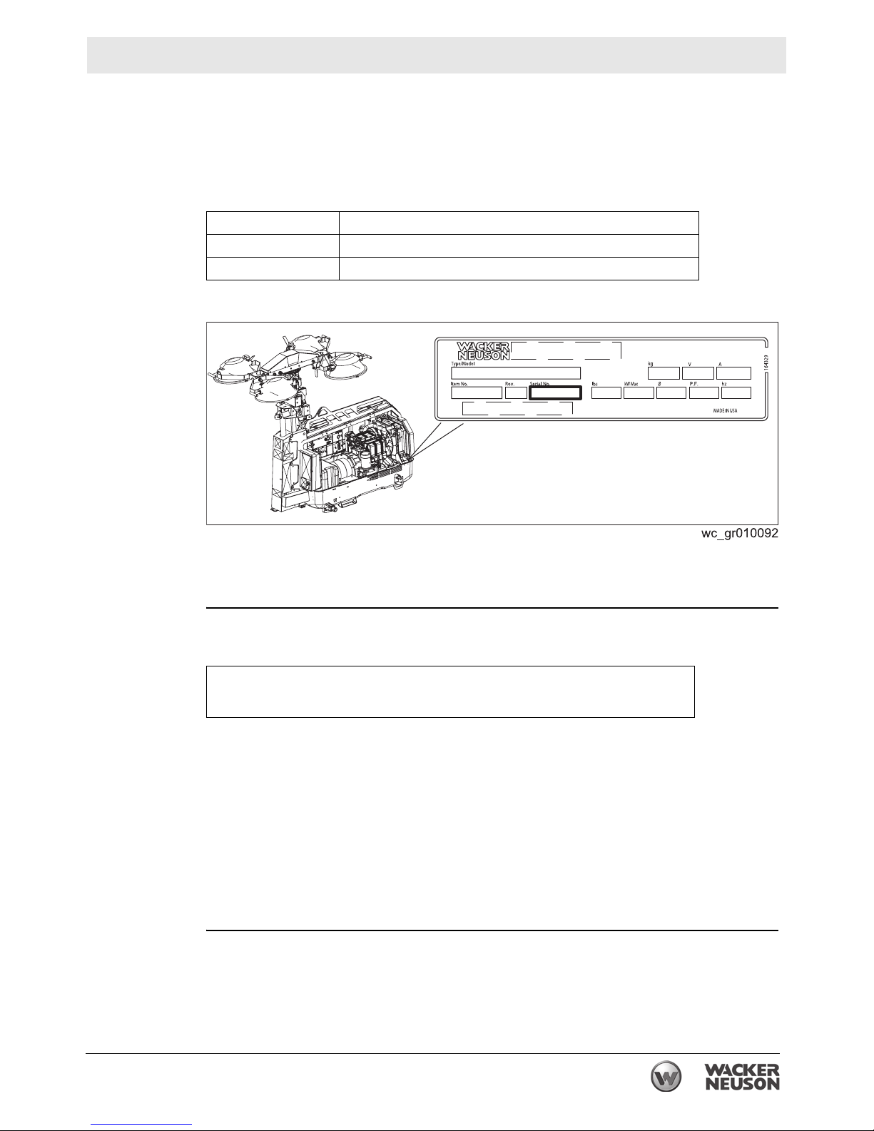
A nameplate listing the model number, item number, revision number, and serial
number is attached to this machine. The location of the nameplate is shown above.
For future reference, record the serial number in the space provided below. You will
need the serial number when requesting parts or service for this machine.
Serial Number:
From this point forward in this documentation, Wacker Neuson Production
Americas LLC will be referred to as Wacker Neuson.
Keep a copy of the Operator’s Manual with the machine at all times.
Use the separate Parts Book supplied with the machine to order replacement
parts.
If you are missing any of these documents, please contact Wacker Neuson to
order a replacement or visit www.wackerneuson.com.
When ordering parts or requesting service information, be prepared to provide
the machine model number, item number, revision number, and serial number.
This manual provides information and procedures to safely operate and main-
tain the above Wacker Neuson model(s). For your own safety and to reduce the
risk of injury, carefully read, understand, and observe all instructions described
in this manual.
wc_tx003091gb.fm 3
Page 4

Foreword LTN 6L-V
Wacker Neuson expressly reserves the right to make technical modifications,
even without notice, which improve the performance or safety standards of its
machines.
The information contained in this manual is based on machines manufactured
up until the time of publication. Wacker Neuson reserves the right to change
any portion of this information without notice.
The illustrations, parts, and procedures in this manual refer to Wacker Neuson
factory-installed components. Your machine may vary depending on the
requirements of your specific region.
Manufacturer’s
approval
This manual contains references to approved parts, attachments, and
modifications. The following definitions apply:
Approved parts or attachments are those either manufactured or provided by
Wacker Neuson.
Approved modifications are those performed by an authorized Wacker Neu-
son service center according to written instructions published by Wacker Neuson.
Unapproved parts, attachments, and modifications are those that do not
meet the approved criteria.
Unapproved parts, attachments, or modifications may have the following
consequences:
Serious injury hazards to the operator and persons in the work area
Permanent damage to the machine which will not be covered under warranty
Contact your Wacker Neuson dealer immediately if you have questions about
approved or unapproved parts, attachments, or modifications.
4 wc_tx003091gb.fm
Page 5

LTN 6L-V
Table of Contents
Foreword 3
1 Safety Information 7
1.1 Signal Words Used in this Manual ....................................................... 7
1.2 Machine Description and Intended Use ............................................... 8
1.3 Safety Guidelines for Operating the Machine ....................................... 9
1.4 Lamp Safety ....................................................................................... 11
1.5 Hydraulic Fluid Safety ........................................................................ 11
1.6 Service Safety .................................................................................... 11
1.7 Operator Safety while Using Internal Combustion Engines ............... 14
1.8 Safety Guidelines for Lifting and Transporting the Machine ............... 15
1.9 Radiation Compliance ........................................................................ 15
2 Labels 16
2.1 Label Locations .................................................................................. 16
2.2 Label Meanings .................................................................................. 18
3 Lifting the Machine 24
4 Operation 25
4.1 Preparing the Machine for First Use ................................................... 25
4.2 Grounding the Machine ...................................................................... 25
4.3 Generator Derating ............................................................................. 25
4.4 Refueling the Machine ........................................................................ 26
4.5 Aiming the Lights - LTN-V .................................................................. 27
4.6 Control Panels .................................................................................... 30
4.7 Before Starting ................................................................................... 31
4.8 Positioning the Machine ..................................................................... 32
4.9 Starting the Machine .......................................................................... 33
4.10 Operating the Lights ........................................................................... 34
4.11 Raising the Tower - LTN 6L-V ............................................................ 35
4.12 Manually Rotating the Mast ................................................................ 36
4.13 Lowering the Tower ............................................................................ 37
4.14 Automatic Shutdown .......................................................................... 38
4.15 Stopping the Machine ......................................................................... 38
4.16 Emergency Shutdown Procedure ....................................................... 39
4.17 Receptacle - 50 Hz ............................................................................. 40
wc_bo5200004270_02TOC.fm
5
Page 6

Table of Contents
LTN 6L-V
5 Maintenance 41
5.1 Preparing for Maintenance ..................................................................41
5.2 Periodic Maintenance Schedule ..........................................................42
5.3 Cleaning the Machine ..........................................................................43
5.4 Inspecting the Machine .......................................................................43
5.5 Checking the Engine Oil Level ............................................................44
5.6 Flushing the Radiator ..........................................................................45
5.7 Checking the Engine Coolant Level ....................................................47
5.8 Checking the Air Cleaning System ......................................................48
5.9 Replacing the Air Cleaner ...................................................................49
5.10 Maintaining the Battery ........................................................................50
5.11 Changing the Engine Oil .....................................................................51
5.12 Checking Fan Belt Tension .................................................................53
5.13 Checking Radiator Hoses ....................................................................54
5.14 Performing Coolant Solution Analysis .................................................55
5.15 Testing the Cooling System Pressure .................................................56
5.16 Removing and Replacing Lamps ........................................................58
5.17 Long-Term Storage .............................................................................60
5.18 Machine Disposal / Decommissioning .................................................61
6 Engine Maintenance: Kohler (T4f) 62
7 Troubleshooting 66
8 Technical Data 68
8.1 Engine .................................................................................................68
8.2 Generator ............................................................................................69
8.3 Machine ...............................................................................................69
8.4 Radiation Compliance .........................................................................70
8.5 Dimensions - LTN 6L-V .......................................................................71
8.6 Dimensions - LTN 6L-VS .....................................................................71
9 Schematics 72
9.1 50 Hz ...................................................................................................72
9.2 Generator Capacitor Excitation Schematic 50 Hz ...............................74
9.3 Hydraulic Schematic - LTN 6L-V .........................................................75
9.4 Hydraulic Schematic - LTN 6L-VS .......................................................76
6
wc_bo5200004270_02TOC.fm
Page 7
LTN 6L-V Safety Information
1 Safety Information
1.1 Signal Words Used in this Manual
This manual contains DANGER, WARNING, CAUTION, NOTICE, and NOTE
signal words which must be followed to reduce the possibility of personal injury,
damage to the equipment, or improper service.
This is the safety alert symbol. It is used to alert you to potential personal hazards.
f Obey all safety messages that follow this symbol.
DANGER
DANGER indicates a hazardous situation which, if not avoided, will result in death
or serious injury.
f To avoid death or serious injury from this type of hazard, obey all safety
messages that follow this signal word.
WARNING
WARNING indicates a hazardous situation which, if not avoided, could result in
death or serious injury.
f To avoid possible death or serious injury from this type of hazard, obey all safety
messages that follow this signal word.
CAUTION
CAUTION indicates a hazardous situation which, if not avoided, could result in
minor or moderate injury.
f To avoid possible minor or moderate injury from this type of hazard, obey all
safety messages that follow this signal word.
NOTICE: Used without the safety alert symbol, NOTICE indicates a situation
which, if not avoided, could result in property damage.
Note: A Note contains additional information important to a procedure.
wc_si000700gb.fm
7
Page 8

Safety Information LTN 6L-V
1.2 Machine Description and Intended Use
Machine
description
Intended use
This machine is a mobile, trailer-mounted light tower. The Wacker Neuson Light
Tower consists of a trailer with a cabinet containing a diesel engine, a fuel tank, a
control panel, and an electric alternator. A telescoping tower with four metal halide
lights is vertically mounted to the top of the machine. A hydraulic cylinder,
combined with a cable and pulley system, raises and lowers the telescoping tower.
As the engine runs, the generator converts mechanical energy into electric power.
The metal halide lights run off this power. Receptacle(s) are also provided to power
auxiliary loads. The operator uses the control panel to operate and monitor the
machine.
This machine is intended for the illumination of outdoor areas. This machine is also
intended for the purpose of supplying electrical power to connected loads. Refer to
the machine specifications for the output voltage and frequency, and for the
maximum output power limit of this Light Tower.
This machine has been designed and built strictly for the intended use described
above. Using the machine for any other purpose could permanently damage the
machine or seriously injure the operator or other persons in the area. Machine
damage caused by misuse is not covered under warranty. The following are some
examples of misuse:
Connecting a load that has voltage and frequency requirements that are
incompatible with the machine output
Overloading the machine with a device that draws excessive power during
either continuous running or startup
Operating the machine in a manner that is inconsistent with all federal, state,
and local codes and regulations
Using the machine as a ladder, support, or work surface
Using the machine to carry or transport passengers or equipment
Using the machine as a hoist, or hanging items from the tower
Operating the machine outside of factory specifications
Operating the machine in a manner inconsistent with all warnings found on the
machine and in the Operator’s Manual
This machine has been designed and built in accordance with the latest global
safety standards. It has been carefully engineered to eliminate hazards as far as
practicable and to increase operator safety through protective guards and labeling.
However, some risks may remain even after protective measures have been taken.
They are called residual risks. On this machine, they may include exposure to:
Heat, noise, exhaust, and carbon monoxide from the engine
Heat from the lights
Ultraviolet radiation from the lights
Fire hazards from improper refueling techniques
Fuel and its fumes
Electric shock and arc flash
Personal injury from improper lifting the trailer tongue
8
wc_si000700gb.fm
Page 9

LTN 6L-V Safety Information
Glare from lights (lights may blind drivers of nearby motor vehicles if the lights
are incorrectly positioned)
Typical hazards related to towing a trailer on roads and highways
To protect yourself and others, make sure you thoroughly read and understand the
safety information presented in this manual before operating the machine.
1.3 Safety Guidelines for Operating the Machine
Operator
training
Operator
qualifications
Before operating the machine:
Read and understand the operating instructions contained in all manuals
delivered with the machine.
Familiarize yourself with the location and proper use of all controls and safety
devices.
Contact Wacker Neuson for additional training if necessary.
When operating this machine:
Do not allow improperly trained people to operate the machine. People
operating the machine must be familiar with the potential risks and hazards
associated with it.
Only trained personnel are permitted to start, operate, and shut down the machine.
They also must meet the following qualifications:
have received instruction on how to properly use the machine
are familiar with required safety devices
The machine must not be accessed or operated by:
children
people impaired by alcohol or drugs
Application
area
Be aware of the application area.
Keep unauthorized personnel, children, and pets away from the machine.
Remain aware of changing positions and the movement of other equipment and
personnel in the application area/job site.
Be aware of the application area.
Do not operate the machine in areas that contain flammable objects, fuels, or
products that produce flammable vapors.
Safety
devices,
controls, and
attachments
Only operate the machine when:
All safety devices and guards are in place and in working order.
All controls operate correctly.
The machine is set up correctly according to the instructions in the Operator’s
Manual.
The machine is clean.
The machine’s labels are legible.
wc_si000700gb.fm
9
Page 10

Safety Information LTN 6L-V
To ensure safe operation of the machine:
Do not operate the machine if any safety devices or guards are missing or
inoperative.
Do not modify or defeat the safety devices.
Only use accessories or attachments that are approved by Wacker Neuson.
Safe
operating
practices
Personal
Protective
Equipment
(PPE)
Before
Starting
When operating this machine:
Remain aware of the machine’s moving parts. Keep hands, feet, and loose
clothing away from the machine’s moving parts.
When operating this machine:
Do not operate a machine in need of repair.
Wear the following Personal Protective Equipment (PPE) while operating this
machine:
Close-fitting work clothes that do not hinder movement
Safety glasses with side shields
Hearing protection
Safety-toed footwear
Be sure the machine is on a firm, level surface and will not tip, roll, slide, or fall
while operating.
Never connect machine to other power sources, such as supply mains of power
companies.
Never use the machine if the insulation on the electrical cord is cut or worn
through.
Never raise the tower or operate the machine in high winds.
The tower extends up to 8.7 m (28.54 ft.). Make sure the area above the trailer
is open and clear of overhead wires and obstructions.
Operation
Keep the area under and around the lights clear of people while raising and
lowering the tower.
Do not move the Light Tower while it is operating.
After Use
Stop the engine when the machine is not being operated.
Close the fuel valve on engines equipped with one when machine is not being
operated.
Ensure that the machine will not tip over, roll, slide, or fall when not being
operated.
Store the machine properly when it is not being used. The machine should be
stored in a clean, dry location out of the reach of children.
Lower the tower when not in use, or if high winds or electrical storms are
expected in the area.
The lamps become extremely hot in use! Allow the lamp and fixture to cool
10–15 minutes before handling.
10
wc_si000700gb.fm
Page 11
LTN 6L-V Safety Information
1.4 Lamp Safety
Description
The lamps provided with your Light Tower are electric discharge lamps. They are
designed for use with metal halide ballasts only, and require time to reach full
brightness on initial startup and after a power interruption. These lamps comply
with FDA regulation performance standards 21 CFR 1040-30.
WARNING
Personal injury hazard. Broken or punctured lamps can cause serious skin burns
and eye inflammation from shortwave ultraviolet radiation.
" Do not operate the Light Tower if a lamp is damaged.
f Replace damaged lamps immediately.
Operating
safety
Replace damaged lamps according to the instructions in section Removing /
Replacing Lamps.
Alternative lamps that automatically extinguish when the outer envelope is
broken or punctured are commercially available.
1.5 Hydraulic Fluid Safety
WARNING
Possibility of severe injury. Hydraulic fluid is under high pressure and becomes very
hot during operation.
f To avoid injury, obey the safety instructions listed below.
Safety
instructions
Inspect the hydraulic system thoroughly before operating the machine.
Do not touch hydraulic fluid or hydraulic components while the machine is
operating. Wait until the machine is cool.
Before disconnecting hydraulic fittings or hoses, ensure that all pressure has
been bled from the circuit. Set all controls in neutral, turn engine off, and allow
the fluids to cool before loosening hydraulic fittings or attaching test gauges.
Hydraulic fluid escaping under high pressure may penetrate the skin, cause
burns, blind, or cause other serious injuries or infections. Contact a physician
immediately for treatment if your skin has been penetrated by hydraulic fluid,
even if the wound seems minor.
Fluid leaks from small holes are often practically invisible. Do not use your bare
hands to check for leaks. Check for leaks using a piece of cardboard or wood.
Hydraulic fluid is extremely flammable. Stop the engine immediately if a
hydraulic leak is detected.
After servicing the hydraulics, make sure all components are reconnected to the
proper fittings. Failure to do so may result in damage to the machine and/or
injury to a person on or near the machine.
1.6 Service Safety
wc_si000700gb.fm
11
Page 12

Safety Information LTN 6L-V
Service
training
Precautions
Before servicing or maintaining the machine:
Read and understand the instructions contained in all manuals delivered with
the machine.
Familiarize yourself with the location and proper use of all controls and safety
devices.
Only trained personnel shall troubleshoot or repair problems occurring with the
machine.
Contact Wacker Neuson for additional training if necessary.
When servicing or maintaining this machine:
Do not allow improperly trained people to service or maintain the machine.
Personnel servicing or maintaining the machine must be familiar with the
associated potential risks and hazards.
Follow the precautions below when servicing or maintaining the machine.
Read and understand the service procedures before performing any service to
the machine.
All adjustments and repairs must be completed before operating the machine.
Do not operate the machine with a known problem or deficiency.
All repairs and adjustments shall be completed by a qualified technician.
Turn off the machine before performing maintenance or making repairs.
Remain aware of the machine’s moving parts. Keep hands, feet, and loose
clothing away from the machine’s moving parts.
Re-install the safety devices and guards after repair and maintenance
procedures are complete.
Machine
modifications
Replacing
parts and
labels
When servicing or maintaining the machine:
Use only accessories/attachments that are approved by Wacker Neuson.
When servicing or maintaining the machine:
Do not defeat safety devices.
Do not modify the machine without the express written approval of Wacker
Neuson.
Replace worn or damaged components.
Replace all missing and hard-to-read labels.
When replacing electrical components, use components that are identical in
rating and performance to the original components.
When replacement parts are required for this machine, use only Wacker
Neuson replacement parts or those parts equivalent to the original in all types of
specifications, such as physical dimensions, type, strength, and material.
12
wc_si000700gb.fm
Page 13

LTN 6L-V Safety Information
Cleaning
Personal
Protective
Equipment
(PPE)
When cleaning and servicing the machine:
Keep the machine clean and free of debris such as leaves, paper, cartons, etc.
Keep the labels legible.
When cleaning the machine:
Do not clean the machine while it is running.
Never use gasoline or other types of fuels or flammable solvents to clean the
machine. Fumes from fuels and solvents can become explosive.
Wear the following Personal Protective Equipment (PPE) while servicing or
maintaining this machine:
Close-fitting work clothes that do not hinder movement
Safety glasses with side shields
Hearing protection
Safety-toed footwear
In addition, before servicing or maintaining the machine:
Tie back long hair.
Remove all jewelry (including rings).
Before servicing the Light Tower, make sure the engine start switch is turned to
the OFF position, the circuit breakers are open (off), and the negative terminal
on battery is disconnected. Do not perform even routine service (oil/filter
changes, cleaning, etc.) unless all electrical components are shut down.
Always turn off light circuit breakers and shut down engine before disconnecting
light fixtures or changing light bulbs.
wc_si000700gb.fm
13
Page 14
Safety Information LTN 6L-V
1.7 Operator Safety while Using Internal Combustion Engines
WARNING
Internal combustion engines present special hazards during operation and fueling.
Failure to follow the warnings and safety standards could result in severe injury or
death.
f Read and follow the warning instructions in the engine owner’s manual and the
safety guidelines below.
DANGER
Exhaust gas from the engine contains carbon monoxide, a deadly poison.
Exposure to carbon monoxide can kill you in minutes.
f NEVER operate the machine inside an enclosed area, such as a tunnel, unless
adequate ventilation is provided through such items as exhaust fans or hoses.
Operating
safety
Refueling
safety
When running the engine:
Keep the area around exhaust pipe free of flammable materials.
Check the fuel lines and the fuel tank for leaks and cracks before starting the
engine. Do not run the machine if fuel leaks are present or the fuel lines are
loose.
When running the engine:
Do not smoke while operating the machine.
Do not run the engine near sparks or open flames.
Do not touch the engine or muffler while the engine is running or immediately
after it has been turned off.
Do not operate a machine when its fuel cap is loose or missing.
Do not start the engine if fuel has spilled or a fuel odor is present. Move the
machine away from the spill and wipe the machine dry before starting.
When refueling the engine:
Clean up any spilled fuel immediately.
Refill the fuel tank in a well-ventilated area.
Replace the fuel tank cap after refueling.
Use suitable tools for refueling (for example, a fuel hose or funnel).
When refueling the engine:
Do not smoke.
Do not refuel a hot or running engine.
Do not refuel the engine near sparks or open flames.
14
wc_si000700gb.fm
Page 15

LTN 6L-V Safety Information
1.8 Safety Guidelines for Lifting and Transporting the Machine
When lifting the machine:
Make sure slings, chains, hooks, ramps, jacks, forklifts, cranes, hoists, and any
other type of lifting device used is attached securely and has enough weightbearing capacity to lift or hold the machine safely. See section Technical Data
for machine weight.
Remain aware of the location of other people when lifting the machine.
Only use the lifting points and tie-downs described in the Operator’s Manual.
Make sure the transporting vehicle has sufficient load capacity and platform size
to safely transport the machine.
To reduce the possibility of injury:
Do not stand under the machine while it is being lifted or moved.
Do not get onto the machine while it is being lifted or moved.
1.9 Radiation Compliance
This machine meets the radio interference radiated emission requirements of
European Standard EN 13309 for Construction Machinery.
The lamps provided with this machine are electric discharge lamps. They are
designed for use with metal halide ballasts only, and require time to reach full
brightness on initial startup and after a power interruption. These lamps comply
with FDA regulation performance standards 21 CFR 1040-30.
wc_si000700gb.fm
15
Page 16

Labels LTN 6L-V
2 Labels
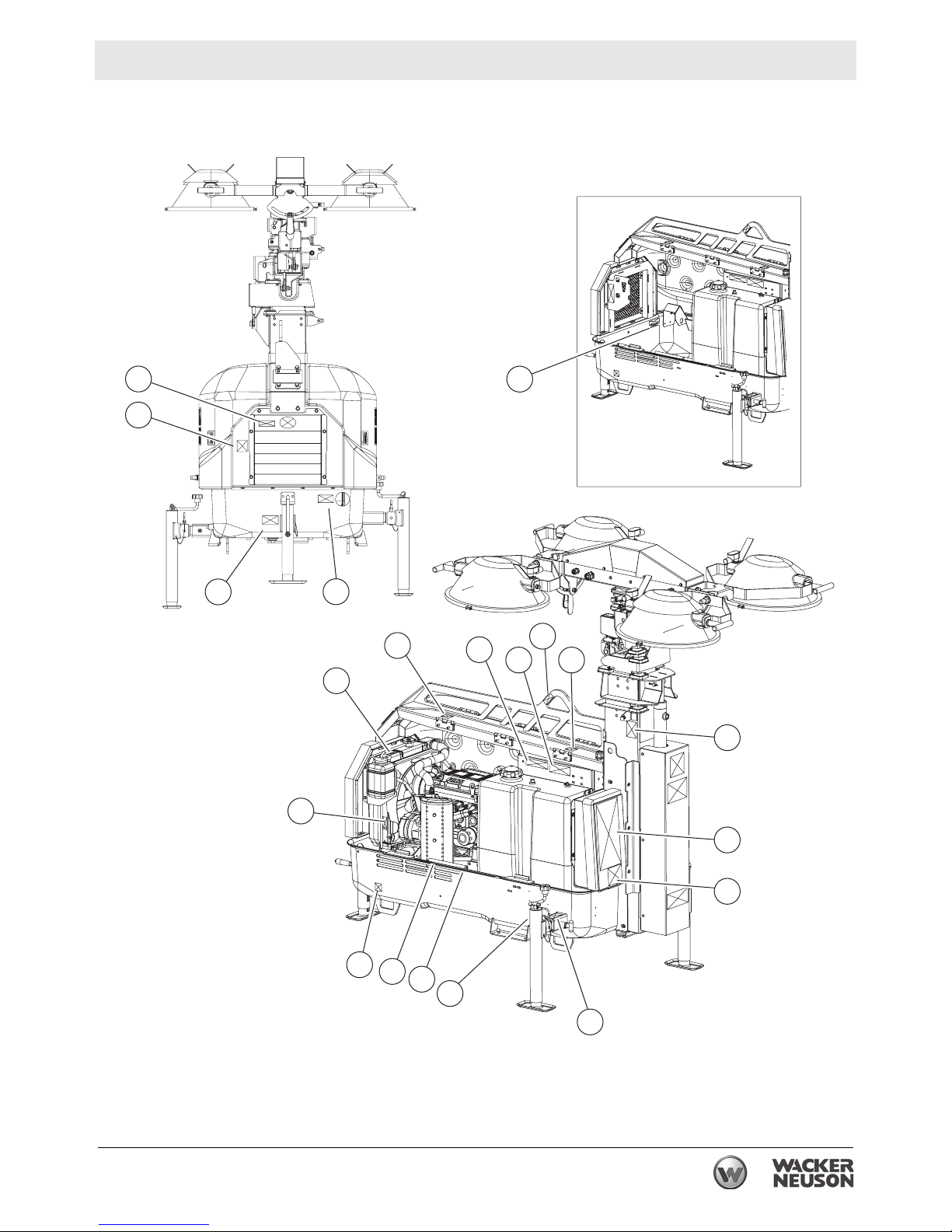
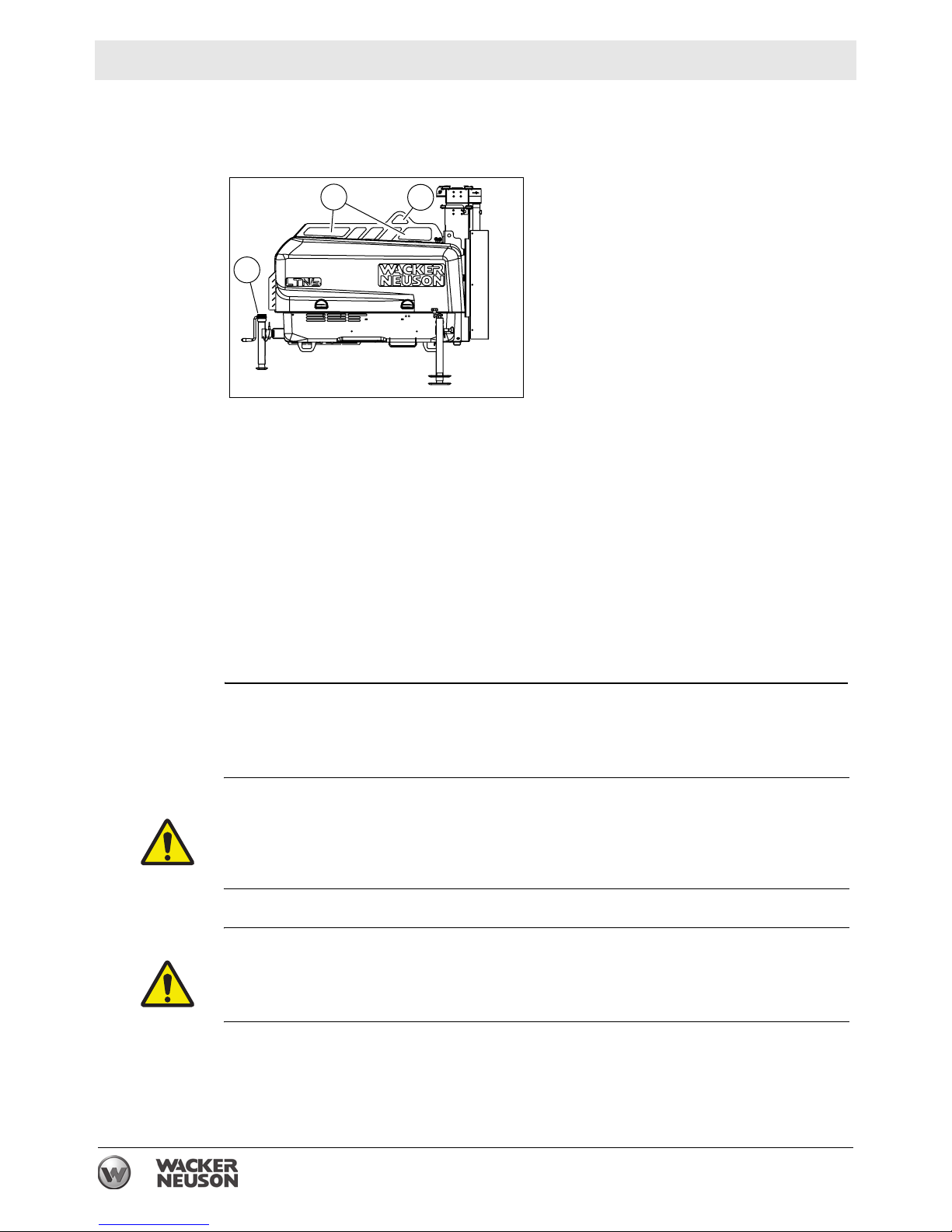
2.1 Label Locations
F
O
F
A
C
D
B
E
G
H
N
T
R
L
K
J
M
R
P
R
DD
R
wc_gr009306
16 wc_si000701gb.fm
Page 17
LTN 6L-V Labels
W
S
M
N
Y
X
CC
F
V
U
O
F
A
wc_si000701gb.fm 17
R
BB
J
Z
I
R
M
wc_gr009307
Page 18
Labels LTN 6L-V
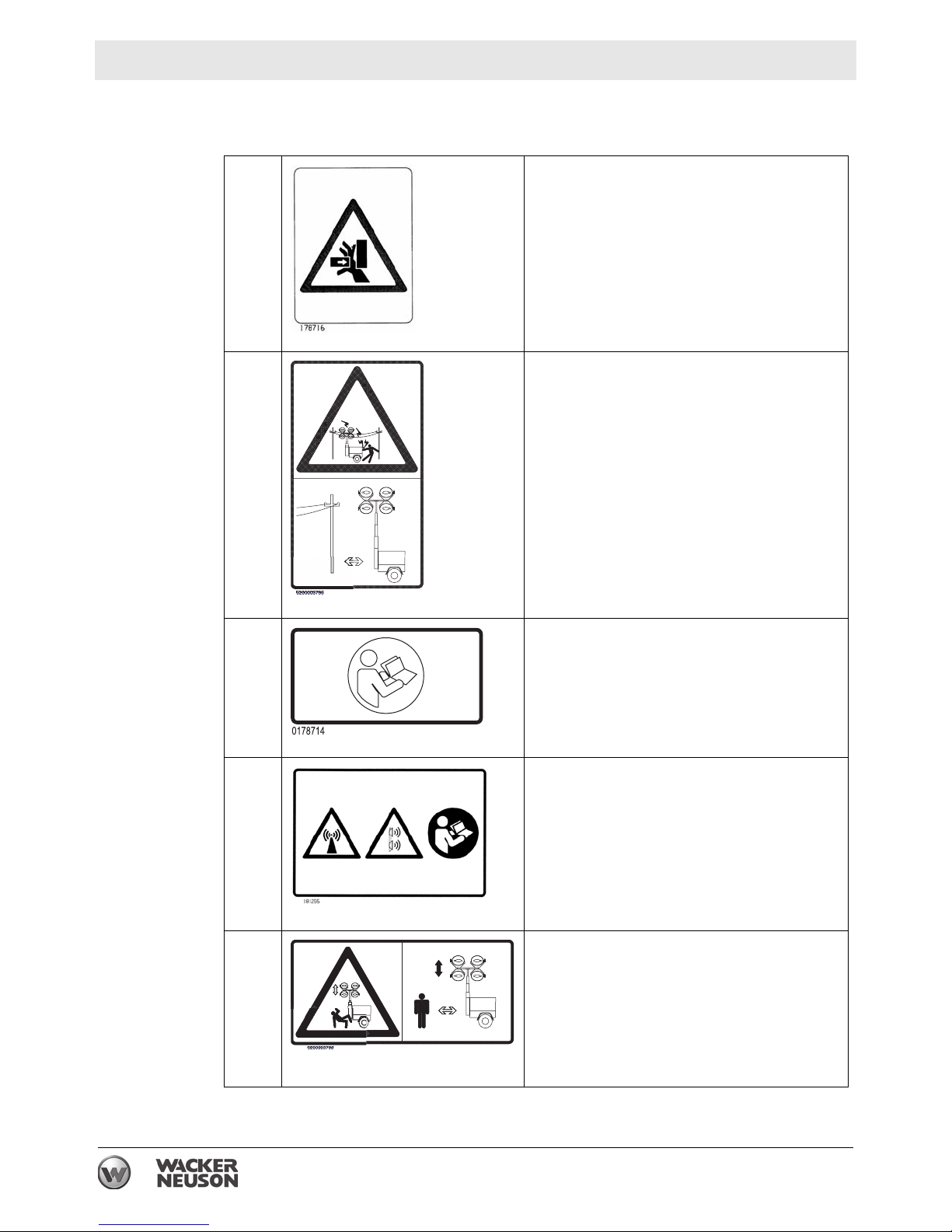
2.2 Label Meanings
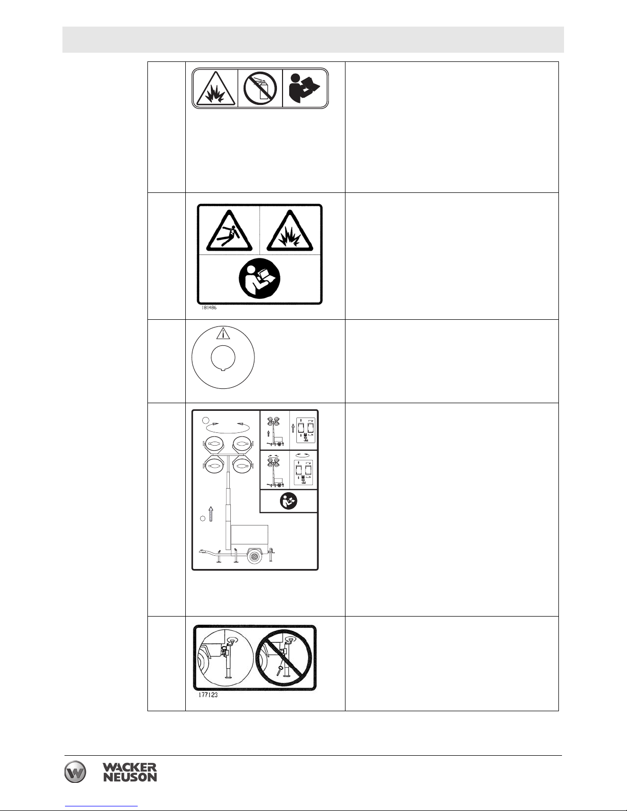
A
B
WARNING
Avoid crushing area.
DANGER
Contact with overhead electrical power lines
will cause serious injury or death. Do not
position Light Tower under electrical power
lines.
C
D
E
Read and understand the supplied Operator’s Manual before operating the machine.
Failure to do so increases the risk of injury to
yourself and others.
WARNING
Ultraviolet radiation from lamp can cause
serious skin and eye irritation. Use only with
undamaged lamps. Use only with provided
undamaged lens cover and fixture.
WARNING
Crushing hazards.
Stand clear of front and rear of machine
when tower is being raised or lowered.
18 wc_si000701gb.fm
Page 19
LTN 6L-V Labels
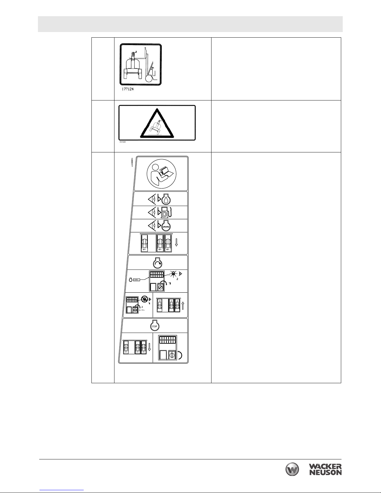
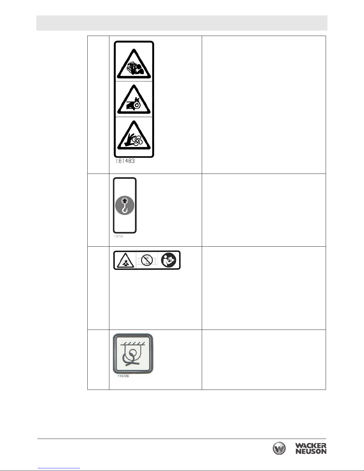
F
G
H
Fork lift pocket
WARNING
Roll-over hazard
To prevent injury or equipment damage,
avoid high speeds and sharp turns when
towing.
See Operator’s Manual for metal halide lamp
information and troubleshooting.
BEFORE STARTING THE ENGINE:
1. Check levels of
Engine oil
Fuel
Coolant
2. Move the circuit breakers to the OFF
position.
TO START THE ENGINE:
1. On the engine control panel, turn the key
switch to the PREHEAT position; the
indicator light will illuminate during
preheating.
2. When the PREHEAT indicator light goes
out, turn the key switch to the START
position for a maximum of 15 seconds.
3. When the engine is running, move the
circuit breakers to the ON position.
TO SHUT DOWN THE MACHINE:
Move the circuit breakers to the OFF
position.
Turn the key switch to the OFF
position to stop the engine.
wc_si000701gb.fm 19
Page 20
Labels LTN 6L-V
5200005891
52000037975200003797
1
2
2
1
I
WARNING
Explosion hazard. Do not use evaporative
starting fluids such as ether on this engine.
5200005891
The engine is equipped with a cold starting
aid. Using evaporative starting fluids can
cause an explosion which can cause engine
damage, personal injury, or death. Read and
follow the engine starting instructions in this
Operator's Manual.
J
WARNING
Electric shock and arc flash can cause serious injury or death. Electrical storage device
within. Contact a qualified electrician for service or to open electrical box.
K Emergency stop
L
2
1
Raising the Tower and Rotating the Lights
1. To raise the tower, press the upper half of
the switch on the left.
2
2. To rotate the lights, press the upper or
lower half of the switch on the right.
Read the Operator’s Manual for more information.
1
M
Insert jack locking pin before extending jack.
20 wc_si000701gb.fm
Page 21
LTN 6L-V Labels
178709
N
O
WARNING
Pressurized contents. Do not open when hot
Pinching / cutting hazards. Rotating machinery.
NOTICE
Lifting point
P
R
DANGER
Using a Light Tower indoors CAN KILL YOU
IN MINUTES. Light Tower exhaust contains
carbon monoxide. This is a poison you cannot see or smell.
NEVER use inside a home or garage, EVEN
IF doors and windows are open.
Only use OUTSIDE and far away from windows, doors, and vents.
Read the Operator’s Manual.
Tie-down point
wc_si000701gb.fm 21
Page 22
Labels LTN 6L-V
ULSD-S15
LSD-S500
180563
S
T
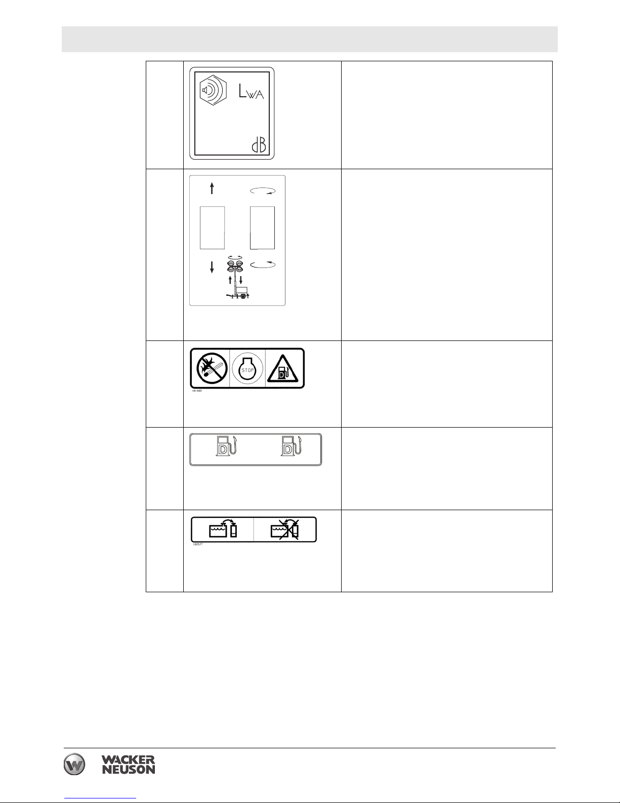
U
Guaranteed sound power level in db(A)
91
Tower and light adjustment switches.
The switch on the left controls the up and
down movement of the tower.
The switch on the right controls the auto-
rotation of the tower (optional).
DANGER
No sparks, flames, or burning objects near
machine. Stop the engine before adding fuel.
Use only diesel fuel.
V
X
180563
LSD-S500
Low sulfur fuel or ultra low sulfur fuel only
ULSD-S15
Coolant overflow bottle only, not a return
system.
22 wc_si000701gb.fm
Page 23
LTN 6L-V Labels
178732
5200003798
STOP
3
2
1
4
2
3
UTILITY 159116
U.S.PAT.Nos.: 6012285, 6471476,
D416858, D454357 OTHER U.S. AND
FOREIGN PATENTS PENDING
Y
Z
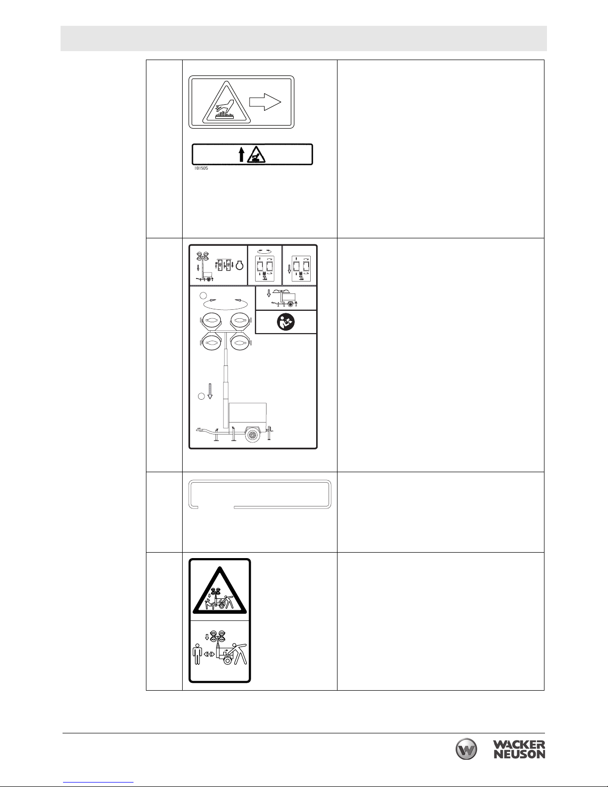
W
BB
178732
1
3
WARNING
Hot surface
2
STOP
3
Shutting off the Lights and Lowering the
Tower
1. Stop the engine and shut off the lights.
2
4
2. Rotate the lights so the light bar is parallel
to the machine. To rotate the lights, press
the upper or lower half of the switch on
the right.
3. To lower the tower, press the lower half of
the switch on the left.
4. Loosen the handle and rotate the lights so
that they are level with the ground.
Read the Operator’s Manual for more information.
5200003798
CC
U.S.PAT.Nos.: 6012285, 6471476,
D416858, D454357 OTHER U.S. AND
FOREIGN PATENTS PENDING
UTILITY 159116
DD
This machine may be covered by one or
more patents.
WARNING
Crushing hazards.
Stand clear of the front of the machine when
the tower is being lowered with the hydraulic
manual override valve.
wc_si000701gb.fm 23
Page 24
Lifting the Machine LTN 6L-V
3 Lifting the Machine
Overview
Requirements
The machine is equipped with fork lift pockets (a) and a lifting eye (b).
a
b
c
wc_gr009316
Before lifting the machine, make sure that the following requirements have been
met.
Machine is stopped
Tower is completely lowered
Lights have been rotated so that they are level with the ground
Doors are properly latched
Outriggers have been returned to their travel position
Outrigger bars and jacks are locked in place
Rear jack (c) is completely cranked in and rotated 90°
Lifting devices have enough weight-bearing capacity to lift and move the
machine safely. See Technical Data.
Lifting the
machine
To lift the machine:
use a forklift and the designated forklift pockets
attach a sling or chain to the lifting eye
WARNING
Crushing hazard. The machine can drop if the lifting gear is attached to any part of
the machine other than the designated lifting locations. Only the designated lifting
locations can support the weight of the machine.
f Use only the supplied forklift pockets or lifting eye to lift the machine.
WARNING
Crushing hazard.
f Keep people away from the machine as it is being lifted. Do not allow anyone to
stand beneath the machine.
24
wc_tx003093gb.fm
Page 25

LTN 6L-V Operation
4 Operation
4.1 Preparing the Machine for First Use
1. Make sure all loose packaging materials have been removed from the machine.
2. Check the machine and its components for damage. If there is visible damage,
do not operate the machine! Contact your Wacker Neuson dealer immediately
for assistance.
3. Take inventory of all items included with the machine and verify that all loose
components and fasteners are accounted for.
4. Attach component parts not already attached.
5. Add fluids as needed and applicable, including fuel, engine oil, and battery acid.
6. Move the machine to its operating location.
4.2 Grounding the Machine
Per ISO 8528-8, this machine is designed with an IT Network power system. Do
not externally ground this machine.
4.3 Generator Derating
Description
Derating
percentages
All generator sets are subject to derating (reduced power output) depending on the
altitude and ambient temperature. Derating should not affect the operation of the
floodlights, although it will reduce the available reserve power to the receptacle.
Power ratings are typically reduced by the following percentages:
3% per 300 m (1000 ft.) elevation above sea level
2% per 5.5°C (10°F) increase in ambient temperature above 25°C (78°F).
wc_tx003097gb.fm
25
Page 26

Operation LTN 6L-V
4.4 Refueling the Machine
Requirements
Procedure
Machine shut down
Engine cool
Machine/fuel tank level with the ground
Fresh, clean fuel supply
Perform the procedure below to refuel the machine.
WARNING
Fire hazard. Fuel and its vapors are extremely flammable. Burning fuel can cause
severe burns.
f Keep all sources of ignition away from the machine while refueling.
f Refuel only when the machine is outdoors.
f Clean up spilled fuel immediately.
1. Remove the fuel cap (a).
a
Result
D
wc_gr008825
2. Fill the fuel tank, allowing a minimum of 50 mm (2 in.) expansion space between
the fuel level and the top of the tank.
CAUTION
Fire and health hazard. Fuel expands when heated. Expanding fuel in an over-filled
tank can lead to spills and leaks.
f Do not fill the fuel tank completely.
3. Reinstall the fuel cap.
The procedure to refuel the machine is now complete.
26
wc_tx003097gb.fm
Page 27

LTN 6L-V Operation
4.5 Aiming the Lights - LTN-V
Overview
Requirements
Aiming the
light fixtures
Each individual light fixture can be aimed up, down, left, or right independent of
one another. There are four total light fixtures on each machine.
The light bars, which include two light fixtures each, can be tilted 45° in each
direction from horizontal.
This procedure is not for rotating the lights as a single unit while the tower is
raised. This procedure requires the tower is lowered and the is machine
stopped. To rotate the lights, see topic Rotating the Lights.
Before adjusting the lights, make sure that the following conditions have been met.
Machine is stopped
Tower is completely lowered
Lights are cool to the touch
Aiming Up or Down
Perform the procedure below to aim an individual light fixture up or down.
1. Loosen the T-handle (a) and aim the light up or down.
NOTICE: Do not loosen the nut (b). Damage to the light fixture may occur.
a
a a
b
2. Tighten the T-handle (a) when the light is aimed properly.
3. Repeat steps 1—3 for each remaining light fixture, if desired.
This procedure continues on the next page.
wc_gr009317
wc_tx003097gb.fm
27
Page 28

Operation LTN 6L-V
Continued from the previous page.
Aiming Left or Right
1. Grasp the light fixture and aim it to the light left or right. If necessary, loosen the
bracket nut (c) to allow movement of the fixture.
NOTICE: Do not loosen the nut (b). Damage to the light fixture may occur.
c c
b
c
wc_gr010507
2. If loosened, tighten the bracket nut (c) when the light is aimed properly.
Note: The bracket nut (c) should be only tight enough so that slight resistance is
present when aiming the fixture.
3. Repeat steps 1—2 for each remaining light fixture, if desired.
This procedure continues on the next page.
28
wc_tx003097gb.fm
Page 29

LTN 6L-V Operation
Continued from the previous page.
Aiming the
light bars
Perform the procedure below to aim the light bars.
1. Loosen the knob (d), grasp the handles (e), and tilt the light bar to the desired
angle.
2. Tighten the knob (d) when the light bar is in the desired position.
3. Repeat steps 1—2 for the other light bar, if desired.
wc_tx003097gb.fm
29
Page 30

Operation LTN 6L-V
4.6 Control Panels
1
e
a
230V 115V
e
230VAC
a
b
c d
b
f g h k l m n vu
o
p
q
2
Ref. Description Ref. Description
Floodlight control panel
1
Engine control panel k High coolant temp. shutdown
2
Tower switch panel l Alternator indicator
3
25A circuit breaker m Auxiliary lights (not used)
a
30A lights circuit breaker n Glow plug indicator
b
16A circuit breaker o Air filter restriction indicator
c
16A receptacle p Auxiliary lights (not used)
d
Hour meter q Key access door
e
Low fuel indicator (not used) u Tower switch (raise / lower)
f
Safety shutdown indicator v Lights rotation switch
g
Low oil pressure shutdown
h
c d
3
wc_gr009945
wc_tx003097gb.fm
30
Page 31

LTN 6L-V Operation
4.7 Before Starting
Before putting the Light Tower into service, review each item on the following
checklist. Light Towers often run unattended for long periods of time. Therefore, it
is important to make sure that the machine is set up properly to avoid possible
operating problems.
CAUTION
Improper machine setup may cause injury or equipment damage.
f Perform all pre-start checks listed below. Do not operate the machine until all
items on the checklist have been addressed.
Check
machine
condition
Check the
engine
Review safety
information
Verify that the machine is level and positioned on a stable surface.
Perform a walk-around to check for visible damage.
Inspect the lights and lamps: ensure that glass is not broken or cracked.
Ensure that all electrical connections are tight.
Verify that all electrical cords are in serviceable condition with no exposed wires,
cuts, or cracks in the insulation.
Close and secure access covers before starting the machine.
Check fuel, engine oil, and coolant levels. Add fluids if necessary.
Verify that the air filter element is clean and undamaged. Replace if necessary.
Check to make sure no debris has lodged in vents, near the radiator, or around
the fan.
Check to make sure that the exhaust compartment is clean and nothing is
touching the muffler or exhaust pipes.
Check fan belt and hoses on engine for loose connections or fraying. Tighten or
replace as required.
Review and follow instructions provided in the “Safety Information” chapter at
the beginning of this Operator’s Manual.
wc_tx003097gb.fm
31
Page 32

Operation LTN 6L-V
4.8 Positioning the Machine
DANGER
Asphyxiation hazard. Exhaust gas from the machine contains carbon monoxide, a
deadly poison you cannot see or smell. Exposure to carbon monoxide can kill you
in minutes.
f Position the machine so that exhaust will not enter any nearby structures.
WARNING
Fire hazard. Do not move the machine while it is running.
f Shut down the machine before moving or repositioning it.
WARNING
Electric shock hazard. The tower extends up to 9 m (30 ft.) and could contact
overhead wires or obstructions.
f
Position the trailer on a firm, flat surface clear of overhead wires and obstructions.
CO Alarms
Requirements
WARNING
Fire hazard. Machines positioned on a hill or an incline may slide, break away or
roll over.
f Do not position the machine on a hill or an incline.
WARNING
Explosion and fire hazard. Risk of severe injury or death.
f Do not operate the machine near flammable vapors, fuels, or combustibles.
Because this machine produces carbon monoxide (CO), Wacker Neuson
recommends that CO alarms be installed in all structures in close proximity to the
machine. CO alarms provide an extra measure of protection against this poison
that you cannot see or smell.
Install battery-operated CO alarms or plug-in CO alarms with battery backup,
according to the manufacturer’s instructions. CO alarms should be certified to the
requirements of the latest safety standards (UL 2034, IAS 6-96, or CSA 6.19.01).
Test the CO alarm batteries monthly.
Position the machine:
so that machine exhaust will not enter nearby structures.
so that the machine does not block traffic.
so that the machine is not near any combustible material or flammable vapor.
so that all of the machine’s access doors/panels may be accessed.
so that the area to be illuminated is at or below the level of the lights.
so that there is room around the machine for the outriggers to be extended.
32
wc_tx003097gb.fm
Page 33

LTN 6L-V Operation
E
M
E
R
G
E
N
C
Y
4.9 Starting the Machine
Pre-start
checklist
NOTICES
Check the following items before starting the machine.
Engine oil, fuel and coolant are filled to the proper levels.
Electrical cables in good condition with no cuts or abrasions in the insulation.
Circuit breakers (a, b, c) are in their “OFF” positions.
Emergency stop switch (t) is pulled out.
All loads are disconnected from the machine.
Do not use evaporative starting fluids (i.e., ether) to start the engine.
Do not start the engine under load.
If the fuel tank was empty, you many need to bleed the fuel lines. Refer to the
engine manufacturer’s documentation.
n
230VAC
t
a
b
c
q
Procedure
wc_gr009357
Follow the procedure below to start the machine.
1. Rotate the starting key (q) one click to the right.
The glow plug indicator (n) will illuminate.
The glow plug indicator will turn off when the engine is preheated.
2. Immediately rotate and hold the starting key to the “START” position until the
engine starts, then release the key.
NOTICE: Cranking the engine longer than 20 seconds can cause damage. If the
engine does not start, return the starting key to the “OFF” position and wait 1
minute for the starter motor to cool before proceeding.
3. Allow the engine to warm up before operating the lights.
Note: If the oil does not reach operating pressure within 30 seconds, the engine
will stop. You must return the starting key to the “OFF” position for 30 seconds
before restarting the engine.
wc_tx003097gb.fm
33
Page 34

Operation LTN 6L-V
4.10 Operating the Lights
Requirements
Procedure
Notes
All items in “Before Starting” checklist have been checked
Tower is raised to the desired height
Engine is running and has warmed up
Perform the procedure below to operate the lights.
1. Turn on the main circuit breaker (a).
a b
wc_gr009327
2. Turn on individual circuit breakers (b) one at a time.
Metal halide floodlights require a warm-up time of 5–15 minutes before they
reach full brightness.
After turning the lights off, a cool-down time of 10 minutes is necessary before
they can be turned on again.
34
wc_tx003097gb.fm
Page 35

LTN 6L-V Operation
4.11 Raising the Tower - LTN 6L-V
Overview
Procedure
The tower is raised by the action of a hydraulic cylinder (c).
Note: The tower can be raised without running the engine.
WARNING
Personal injury hazard. Raising or lowering the tower creates situations that if not
avoided, will cause death or serious injury from striking, crushing, pinching,
electrocution, etc.
f Keep the area under and around the lights clear of people and obstructions
while raising and lowering the tower.
Perform the procedure below to raise the tower.
1. If equipped, engage the parking brake on the trailer.
Note: The tower will not raise if the brake is not engaged.
2. Aim the lights. See topic Aiming the Lights.
3. Start the engine. See topic Starting the Machine.
4. Turn on the circuit breakers (a,b). See topic Operating the Lights.
c
5. Press and hold the upper half of the tower switch (d). Release the switch when
the tower reaches the desired height. See topic Rotating the Mast for more
information.
a b d e
wc_gr009319
wc_tx003097gb.fm
35
Page 36

Operation LTN 6L-V
4.12 Manually Rotating the Mast
Overview
Procedure
The operator can rotate the mast 360° while the tower is lowered.
To rotate the mast, perform the procedure below.
1. Pull out the locking pin (a) on the bottom of the mast.
2. Rotate the mast to the desired position.
3. Engage the locking pin (a).
Note: Be sure the locking pin seats into a groove on the sprocket.
36
wc_tx003097gb.fm
Page 37

LTN 6L-V Operation
4.13 Lowering the Tower
Overview
Notes
Procedure
A low-voltage electrical circuit controls the release of pressure in the hydraulic
cylinder (c). When pressure is released, the tower will lower.
The engine does not need to be running to lower the tower.
The hydraulic circuit includes a pressure release valve that lowers the tower in
an emergency situation. See topic Emergency Shutdown Procedure.
If the parking brake on the trailer is disengaged while the tower is raised, it will
lower automatically.
WARNING
Personal injury hazard. Raising or lowering the tower creates situations that if not
avoided, will cause death or serious injury from striking, crushing, pinching,
electrocution, etc.
f Keep the area under and around the lights clear of people and obstructions
while raising and lowering the tower.
Perform the procedure below to lower the tower.
1. Stop the engine.
2. Turn off the circuit breakers (a, b).
wc_tx003097gb.fm
c
a b d
wc_gr009321
3. Press and hold the lower half of the tower switch (d). Release the switch when
the tower is completely lowered.
37
Page 38

Operation LTN 6L-V
4.14 Automatic Shutdown
Description
This machine is equipped with a low oil, high temperature automatic shutdown
system. This system will automatically interrupt the fuel supply to the engine if the
oil pressure drops too low or the engine exceeds normal operating temperatures.
Resetting
after
If an automatic shutdown occurs, the engine will stop. Return the key switch to the
off position to reset the system.
automatic
shutdown
See Troubleshooting or contact Wacker Neuson Product Support if automatic
shutdown frequently occurs.
4.15 Stopping the Machine
NOTICE: Do not stop the machine without turning off the lights. Damage to the
electrical generator will occur.
Procedure
Follow the procedure below to stop the machine.
1. Remove all connected loads from the machine.
2. Turn the circuit breakers (a, b, c) off.
230VAC
q
b ca
wc_gr009360
3. Rotate the starting key (q) to the “OFF” position.
38
wc_tx003097gb.fm
Page 39

LTN 6L-V Operation
4.16 Emergency Shutdown Procedure
General
procedures
Hydraulic
release valve
If a breakdown or accident occurs while the machine is operating, follow the
procedure below:
1. Stop the engine.
2. Disconnect tools.
3. Lower the tower.
4. Allow the machine to cool before opening the cabinet.
5. Contact the rental yard or machine owner for further instructions.
The hydraulic pump (b) is equipped with a pressure release valve (c). This valve
enables the tower to be lowered manually.
If electrical power is lost, or the tower switch is inoperable, pull out and hold the
knob on the pressure release valve. The hydraulic cylinder will retract and the
tower will lower. Push the knob to close the valve after the tower is fully lowered.
WARNING
Crushing / striking hazard.
f Verify that no one is standing next to the machine while the tower is being low-
ered.
wc_tx003097gb.fm
39
Page 40

Operation LTN 6L-V
4.17 Receptacle - 50 Hz
Description
NOTICES
This machine is equipped with a convenience receptacle (d) for running
accessories and tools from the generator. A circuit breaker (c) protects the
receptacle. Power to the receptacle is available any time the engine is running and
the circuit breaker is on.
230VAC
c d
wc_gr009361
Obey the instructions below to avoid damaging the machine, accessories, or tools.
Do not use frayed or damaged cords or plugs with the convenience receptacle.
The maximum wattage (lights on) drawn from the receptacles shall not exceed:
convenience receptacle-840W
230V receptacle-1680W
Use only tough rubber-sheathed flexible cable or equivalent. (per 1EC245-4).
When using extension cords or mobile distribution networks, the total length of
cords with a cross-sectional area of 1.5 mm
m (197 ft). For cords with a cross-sectional area of 2.5 mm
2
(0.002 in2) should not exceed 60
2
(0.004 in2), the total
length should not exceed 100 m (328 ft).
This machine generates increased voltage while the lights are reaching full
brightness. To avoid damaging sensitive electronic equipment, do not connect
any such devices to the convenience outlet until the machine and lights have
been operating for at least ten minutes.
40
wc_tx003097gb.fm
Page 41

LTN 6L-V Maintenance
5 Maintenance
WARNING
A poorly maintained machine can malfunction, causing injuries or permanent
damage to the machine.
f Keep the machine in safe operating condition by performing periodic mainte-
nance and making repairs as needed.
5.1 Preparing for Maintenance
Do not perform even routine service (oil/filter changes, cleaning, etc.) unless all
electrical components are shut down. Use the checklist below to prepare this
machine for maintenance.
Move the start switch to “OFF”.
Open the circuit breakers (move to the “OFF” position).
Close the emergency stop switch (push in).
Disconnect the negative terminal on the battery.
Attach a “DO NOT START” sign to the control panel.
If the unit is connected to a remote start or transfer switch, make sure the
remote switch is also off and tagged.
wc_tx003099gb.fm
41
Page 42

Maintenance LTN 6L-V
5.2 Periodic Maintenance Schedule
The table below lists basic machine maintenance. Tasks designated with check
marks may be performed by the operator. Tasks designated with square bullet
points require special training and equipment.
Interval* (hours of service)
(10)
Item
Daily
Clean the machine. 3
Inspect the machine. 3
Check for fluid leaks. 3
Check all fluid levels. 3
Check engine oil. 3
Check fuel level. 3
Replace air filter if indicator light is on.*
Change engine oil.**
Check condition and tension on fan belt.
Check condition of radiator hoses.
Replace oil filter.*
Replace fuel filter.
Replace fan belt.
(250)
3 months
(500)
6 months
(1000)
Yearly
Check valve clearance.
Flush radiator and replace coolant.
Remove sediment in fuel tank.
Replace battery.
Replace radiator hoses and clamps.
Replace fuel pipes and clamps.
* Replace air filter after air filter restriction switch indication or one year. Lombardini does not
recommend the removal of air filter elements for purposes of inspection.
** Change engine oil and filter after first 50 hours of operation.
42
wc_tx003099gb.fm
Page 43

LTN 6L-V Maintenance
5.3 Cleaning the Machine
When
Requirements
As needed
Clean water supply
Mild detergent
Clean, dry cloths
NOTICE: Do not use a pressure washer to clean this machine. Pressurized water
can severely damage the generator and sensitive electronic components.
Interior
Clean the interior of the machine.
Remove rags, containers, or other debris from the cabinet. Nothing should be
stored inside the machine.
Remove leaves and twigs from the exhaust pipe.
Wipe interior surfaces clean of oil, dust, and dirt.
Exterior
Clean the exterior of the machine with clean water and a mild detergent.
5.4 Inspecting the Machine
When
Overview
External
inspection
Internal
inspection
Daily
Inspect the machine before each use. A thorough inspection will help to identify
mechanical faults or potentially unsafe operating conditions. Correct these
problems before operating the machine.
Perform an external inspection of the machine. Check for:
External damage (dents, cracks, broken door latches, etc.)
Loose or missing fasteners
Loose or missing parts
Cut or worn insulation on electrical cords
Damaged light fixtures or lamps
Fluid leaks
Restricted air flow at the engine exhaust
Problems with the trailer (if equipped)—see “Maintaining the Trailer”
Open the access doors on both sides of the machine. Check for:
Damage to control panels, switches, or convenience receptacles
Loose or missing fasteners
Loose or missing parts
Loose or damaged hoses
Fluid leaks
Rags, containers, or other debris inside the cabinet
wc_tx003099gb.fm
43
Page 44

Maintenance LTN 6L-V
2
5.5 Checking the Engine Oil Level
When
Requirements
Procedure
Daily before starting the engine
Engine is stopped and cool to the touch
Machine is on a level surface
Clean, dry cloth
Fresh oil
WARNING
Burn hazard. Engine, engine oil, muffler, and exhaust pipes become extremely hot
during operation.
f Stop the engine and allow the machine to cool before checking the engine oil
level.
Perform the procedure below to check the engine oil level.
1. Remove the dipstick (a) from the engine.
c
a
a
b
Result
wc_gr00936
2. Wipe the dipstick clean and re-insert it.
3. Remove the dipstick again and check the oil level (b). The oil level is acceptable
if it appears between the “MIN” and “MAX” markings on the dipstick.
4. If the oil level is below the “MIN” marking on the dipstick, do not operate the
engine. Add oil as needed through the oil fill (c) to reach an acceptable level.
The oil level has now been checked.
wc_tx003099gb.fm
44
Page 45

LTN 6L-V Maintenance
5.6 Flushing the Radiator
When
Requirements
Procedure
Every 1000 hours or 2 years
Engine is stopped and cool to the touch
Plastic sheet
Container of suitable size to collect drained coolant
Fresh 50/50 coolant/water solution
Perform the procedure below to flush the radiator.
WARNING
Burn hazard. Engine coolant is hot and under pressure at operating temperature.
f Stop the engine and let it cool before flushing the radiator.
NOTICE: Do not add fluid to the over-flow reservoir.
1. Open one of the cabinet doors.
a
wc_tx003099gb.fm
wc_gr009363
2. Slowly rotate the radiator cap (a) counterclockwise to release any remaining
system pressure. Unscrew and remove the radiator cap after the pressure has
been released.
3. Place a plastic sheet and container under the radiator.
This procedure continues on the next page.
45
Page 46

Maintenance LTN 6L-V
Continued from the previous page.
4. Open the radiator drain (b) and let the coolant drain into the container.
b
wc_gr009465
5. Close the radiator drain.
6. Remove the engine block coolant plug and let the remaining coolant drain into
the container.
Important
7. Replace the copper seal and reinstall the plug. Tighten the plug to 16.2 ft.lbs.
(22 Nm).
8. Fill the radiator to approximately 19 mm (3/4 in.) below the bottom of the filler
neck. Add more coolant if necessary to maintain this level.
NOTICE: Do not overfill the radiator. The machine will be damaged.
WARNING
Burn hazard. Coolant can contain alkali.
f Avoid contact with skin and eyes.
9. Inspect the radiator filler cap and seal, hoses, clamps, and plugs for damage.
Replace any damaged parts.
10.Clean and reinstall the radiator filler cap.
Use a long-life ethylene glycol coolant in this engine. Refer to the engine owner’s
manual for more information.
wc_tx003099gb.fm
46
Page 47

LTN 6L-V Maintenance
5.7 Checking the Engine Coolant Level
When
Requirements
Procedure
Daily
Machine shut down
Engine cool
50/50 coolant/water solution (as needed)
NOTICE: Do not use water alone to fill the radiator. Use a long-life ethylene glycol
coolant.
Perform the procedure below to check the engine coolant level.
WARNING
Burn hazard. Engine coolant is hot and under pressure at operating temperature.
f Check the coolant level only after the engine has been shut down and is cool.
NOTICE: Do not add fluid to the over-flow reservior.
1. Open one of the cabinet doors.
2. Slowly rotate the radiator cap (a)
a
counterclockwise to release system
pressure. Unscrew and remove the
radiator cap after the pressure has
been released.
3. Verify that the coolant level of the
radiator is 19 mm (3/4 in.) below the
bottom of the filler neck. Add more
coolant if necessary to maintain this
level.
wc_gr009363
NOTICE: Do not overfill the radiator. The
machine will be damaged.
WARNING
Burn hazard. Coolant can contain alkali.
f Avoid coolant contact with skin and eyes.
4. Inspect the radiator filler cap and filler cap seal for damage. Clean the radiator
filler cap or replace it if necessary.
5. Reinstall the radiator filler cap.
wc_tx003099gb.fm
47
Page 48

Maintenance LTN 6L-V
5.8 Checking the Air Cleaning System
When
Overview
Procedure
Daily
The air cleaning system consists of an air cleaner with a pleated element and inlet
pipe.
Perform the procedure below to check the air cleaning system.
1. Make sure the cover on the air cleaner (a) is installed and securely latched.
a
b
wc_gr009364
2. Make sure the inlet (b) is free from obstructions.
Result
3. Check all hoses and connections. Replace any damaged components.
4. If the air cleaner or inlet are crushed or damaged, replace them immediately.
The air cleaning system has now been checked.
48
wc_tx003099gb.fm
Page 49

LTN 6L-V Maintenance
5.9 Replacing the Air Cleaner
When
Requirements
Background
Procedure
Replace the air filter element when the air filter restriction indicator on the control
panel illuminates.
Machine shut down
Clean, dry cloths
Replacement filter element (as needed)
The air cleaner assembly consists of an enclosure containing a pleated filter
element. The element must be replaced when it becomes dirty or clogged. The
enclosure must also be wiped clean of dust.
wc_gr000540
Follow the procedure below to maintain the air cleaner.
NOTICES
Result
WARNING
Fire hazard.
f Never use gasoline or low flash-point solvents for cleaning the air cleaner.
1. Open the metal latches and remove the cover from the enclosure.
2. Remove the filter element and discard.
3. Clean inside of the enclosure with a clean dry cloth.
4. Place a new filter element into the enclosure.
Do not re-use a damaged filter element. Replace the element even if the
damage is very slight.
Do not tap or strike the filter element to clean it.
Do not wash the filter element.
5. Reinstall the cover, and close the latches.
The air cleaner has now been maintained.
wc_tx003099gb.fm
49
Page 50

Maintenance LTN 6L-V
5.10 Maintaining the Battery
Location
Safety
precautions
The battery (a) is located beneath the control panel.
a
wc_gr009366
WARNING
Explosion hazard. Batteries can emit explosive hydrogen gas.
f Keep all sparks and flames away from the battery.
f Do not short-circuit battery posts.
Observe the following safety precautions to prevent serious damage to the
electrical system.
Do not disconnect the battery while the machine is running.
Do not attempt to run the machine without the battery.
Do not attempt to jump-start the machine.
In the event that the machine has a discharged battery, either replace the
battery with a fully charged battery or charge the battery using an appropriate
battery charger.
Dispose of waste batteries in accordance with local environmental regulations.
Battery
connections
To connect the battery:
Connect the red positive (+) battery cable to the battery.
Connect the black negative (-) battery cable to the battery.
To disconnect the battery:
Stop the engine.
Place all electrical switches in the OFF position.
Disconnect the black negative (-) battery cable from the battery.
Disconnect the red positive (+) battery cable from the battery.
Maintaining
battery
condition
Follow the battery manufacturer’s maintenance recommendations.
Keep battery terminals clean and connections tight.
When necessary, tighten the cables and grease the cable clamps with
petroleum jelly.
Maintain the battery at full charge to improve cold weather starting.
50
wc_tx003099gb.fm
Page 51

LTN 6L-V Maintenance
5.11 Changing the Engine Oil
When
Requirements
Procedures
Change the oil and oil filter (d) every 250 hours.
On new machines, change oil after first 50 hours of operation.
Engine stopped, but still warm.
Plastic sheet
Container of suitable size to collect drained oil
Fresh engine oil (see Technical Data)
Follow the procedure below to change the engine oil.
1. Open the doors and remove oil fill cap (a).
a
b
wc_gr010444
2. Place a plastic cloth and a collection container beneath the oil drain (b).
3. Remove the oil drain plug and open the valve (c) to drain the oil.
d
c
wc_gr010445
4. Close the valve (c) and reinstall the oil drain plug.
5. Fill engine crankcase with recommended oil until the level reaches the “MAX”
line on the dipstick (d).
6. Reinstall the oil fill cap.
This procedure continues on the next page.
wc_tx003099gb.fm
51
Page 52

Maintenance LTN 6L-V
Continued from the previous page.
Follow the procedure below to replace the oil filter (e).
1. Drain the engine oil as described above.
2. Using a filter wrench, remove the installed oil filter (e).
3.Apply a thin coat of oil to the rubber
gasket of the replacement oil filter.
4.Screw the filter on until it just contacts
the filter adapter, then turn it an
additional ½ turn.
NOTICE: Do not use the filter wrench to
tighten the filter. Doing so can over-
e
tighten the filter and damage the seal
surface.
Result
wc_gr010443
6. Refill with oil as described above.
7. Run the engine for about five minutes and check for oil leaks at the seal.
The engine oil has been changed.
Note: Dispose of drained oil in accordance with environmental protection
legislation.
WARNING
Most used oil contains small amounts of materials that can cause cancer and other
health problems if inhaled, ingested, or left in contact with skin for prolonged
periods of time.
f Take steps to avoid inhaling or ingesting used engine oil.
f Wash skin thoroughly after exposure to used engine oil.
5.Wipe the filter area clean.
52
wc_tx003099gb.fm
Page 53

LTN 6L-V Maintenance
5.12 Checking Fan Belt Tension
When
Overview
Procedure
Check the fan belt for proper tension and wear every 250 hours.
Correct fan belt tension is critical to proper engine operation. An over-tensioned fan
belt can damage the belt and bearings. A fan belt that is too loose or worn may slip,
resulting in shortened belt life, increased noise, and loss of power to the fan.
WARNING
Pinching and crushing hazards.
f Stop the engine before checking the fan belt tension.
Perform the procedure below to check the fan belt tension and wear.
1. Open the access door on the fuel tank side of the machine
2. Inspect the fan belt (a) for cuts, frayed edges, tears, or glazed surfaces.
b
a
Result
wc_gr009368
3. Apply 10 kg (22 lb) of force between the fan pulley and alternator. If the
deflection (b) is greater than 1 cm (0.393 in.), the belt tension must be adjusted.
4. Replace the fan belt if it is damaged, worn, or deflects more than the maximum
acceptable distance.
The fan belt tension has now been checked.
wc_tx003099gb.fm
53
Page 54

Maintenance LTN 6L-V
5.13 Checking Radiator Hoses
When
Overview
Procedure
Check the condition of the radiator hoses every 250 hours.
Dry, cracked radiator hoses or loose clamps can cause a coolant leak. A coolant
leak will cause the engine to overheat, possibly leading to permanent damage.
Regular inspection of the radiator hoses will help to identify coolant leaks.
There are two radiator hoses on the LTN. The upper hose (a) supplies coolant to
the engine. The lower hose (b) returns coolant to the radiator.
c
a
c
b
c
wc_gr009375
Perform the procedure below to check the radiator hoses.
1. Inspect each hose for cuts, cracks, abrasions, or bulges. Replace the hose if
any of these conditions exist.
Result
2. Squeeze each hose to check the elasticity. A hose in serviceable condition will
yield to slight pressure. Replace the hose if it appears to be stiff or brittle.
3. Check the hose clamps (c) to make sure that they are tight. Check for coolant
leaks at the hose connections. Tighten loose clamps as needed.
The radiator hoses have now been checked.
54
wc_tx003099gb.fm
Page 55

LTN 6L-V Maintenance
5.14 Performing Coolant Solution Analysis
When
Overview
Requirements
Procedure
Every 500 hours or 12 months, whichever comes first.
Engine coolant must be regularly tested to ensure that it remains at an acceptable
pH level. Unacceptably low pH levels in coolant create an acidic mixture that will
permanently damage the radiator, engine, and engine-related components.
Machine shut down
Engine cool
Coolant test strips (provided by owner/operator)
Perform the procedure below to check the engine coolant level.
WARNING
Burn hazard. Engine coolant is hot and under pressure at operating temperature.
f Test the coolant pH level only after the engine has been shut down and is cool.
1. Slowly rotate the radiator cap (a) counterclockwise to release any remaining
system pressure. Unscrew and remove the radiator cap after the pressure has
been released.
a
2. Dip a coolant test strip into the filler neck and read the pH level.
Coolant pH level tests below 8.5
Coolant pH level tests between 8.5 and
NOTICE: Do not use plain water or any other liquid as engine coolant. Doing so will
quickly corrode and permanently damage the coolant system. Damage caused by
incorrect coolant will not be covered under warranty.
Result
The coolant solution has now been analyzed.
wc_tx003099gb.fm
wc_gr009369
If Then
the coolant is not acceptable for use.
or above 10.5,
10.5,
Drain, flush, and refill the system with a new
ethylene glycol solution (50/50).
the coolant is acceptable for use.
55
Page 56

Maintenance LTN 6L-V
5.15 Testing the Cooling System Pressure
When
Background
Requirements
Test the cooling system pressure every 1200 hours, or 24 months (whichever
comes first).
The cooling system is under pressure while the engine is operating. Internal or
external leaks will cause the cooling system to lose pressure. These leaks can be
detected by forcing pressurized air into the radiator cap and cooling system while
the engine is stopped.
WARNING
Burn hazard. Engine coolant is hot and under pressure at operating temperature.
f Test the cooling system pressure only when the engine is stopped and the radi-
ator is cool to the touch.
WARNING
Burn hazard. Engine coolant may contain alkali.
f Avoid coolant contact with skin and eyes.
Engine is stopped and cool to the touch
Pressure test kit
Cooling system filled (see Checking the Engine Coolant Level)
Procedure
Perform the following procedure to test the cooling system pressure.
1. Slowly rotate the radiator cap (a) counterclockwise to release any remaining
system pressure. Unscrew and remove the radiator cap after the pressure has
been released.
a
wc_gr009369
2. Note the rated operating pressure marked on the outside of the radiator cap.
When this pressure level is reached, a relief valve in the cap discharges coolant
into the overflow bottle.
This procedure continues on the next page.
56
wc_tx003099gb.fm
Page 57

LTN 6L-V Maintenance
Continued from the previous page.
3. Attach the radiator cap (b) to the pressure tester (c) according to the
instructions provided by the manufacturer.
4. Pressure test the radiator cap, observing the pressure reading on the tester.
d
c b
Result
If Then
Pressure holds just below the rated
operating pressure marked on the cap,
Pressure drops, or the rated operating
pressure cannot be reached,
radiator cap is acceptable for use.
radiator cap must be replaced. Contact your
Wacker Neuson dealer.
wc_gr009025
5. Attach the pressure tester to the radiator filler neck (d).
6. Pressure test the cooling system at slightly above the rated operating pressure
marked on the radiator cap. Observe the pressure reading.
If Then
Pressure holds steady, there are no leaks in the cooling system.
Pressure drops, or the rated operating
pressure cannot be reached,
there is an internal or external leak in the
cooling system. Repair the leak before
putting the machine back into service.
The cooling system pressure has now been tested.
wc_tx003099gb.fm
57
Page 58

Maintenance LTN 6L-V
5.16 Removing and Replacing Lamps
Prerequisites
Engine shut down
Light circuit breakers turned OFF
Lamps and fixtures cool to the touch
Eye and hand protection
WARNING
Burn hazard. Lamps become extremely hot in use.
f Allow lamps and fixtures to cool 10–15 minutes before handling.
WARNING
Personal injury hazard. Ultraviolet radiation from the lamps can cause serious skin
and eye irritation.
f Use only undamaged lamps.
f Use the lamps only with undamaged original equipment lenses and fixtures.
WARNING
Explosion hazard. Grease or oil residue on the lamp can cause the outer jacket to
burst or shatter. Hot flying glass particles can cause personal injury, property
damage, burns, or fire.
f Do not operate the lights with a lens that is cracked, damaged, or missing.
f Do not scratch the lamp or subject the lamp to excess pressure.
f Wear eye and hand protection when removing or replacing lamps.
This procedure continues on the next page.
58
wc_tx003099gb.fm
Page 59

LTN 6L-V Maintenance
Continued from the previous page.
Perform the procedures below to remove and install the lamp.
Removing the
lamp
Installing the
lamp
1. Remove the screws (a) securing the flange rings (b) and remove the flange
rings.
c
f
d
b
e
a
wc_gr005881
2. Remove the lens (c) with the gasket (d) attached.
3. Remove the hardware securing one side of the lamp stabilizer (e). Once
removed, swing the lamp stabilizer to the side and unscrew the lamp (f).
1. Screw the lamp in firmly, but not forcibly, to minimize loosening due to vibration.
Secure it with the lamp stabilizer.
2. Install the gasket around the lens and secure the lens to the reflector with the
flange rings and screws.
wc_tx003099gb.fm
59
Page 60

Maintenance LTN 6L-V
5.17 Long-Term Storage
Introduction
When
Preparing for
storage
Stabilizing the
fuel
Extended storage of equipment requires preventive maintenance. Performing
these steps helps to preserve machine components and ensures the machine will
be ready for future use. While not all of these steps necessarily apply to this
machine, the basic procedures remain the same.
Prepare your machine for extended storage if it will not be operated for 30 days or
more.
Follow the procedures below to prepare your machine for storage.
Complete any needed repairs.
Replenish or change oils (engine, exciter, hydraulic, and gearcase) per the
intervals specified in the Scheduled Maintenance table.
Grease all fittings and, if applicable, repack bearings.
Inspect engine coolant. Replace coolant if it appears cloudy, is more than two
seasons old, or does not meet the average lowest temperature for your area.
If your machine has an engine equipped with a fuel valve, start the engine, close
the fuel valve, and run the engine until it stops.
Consult the engine owner’s manual for instructions on preparing the engine for
storage.
After completing the procedures listed above, fill the fuel tank completely and add a
high-quality stabilizer to the fuel.
Choose a stabilizer that includes cleaning agents and additives designed to
coat/protect the cylinder walls.
Make sure the stabilizer you use is compatible with the fuel in your area, fuel
type, grade and temperature range. Do not add extra alcohol to fuels which
already contain it (for example, E10).
For engines with diesel fuel, use a stabilizer with a biocide to restrict or prevent
bacteria and fungus growth.
Add the correct amount of stabilizer per the manufacturer’s recommendations.
Storing the
machine
Perform these remaining steps to store your machine.
Wash the machine and allow it to dry.
Move the machine to a clean, dry, secure storage location. Block or chock
wheels to prevent machine movement.
Use touch-up paint as needed to protect exposed metal against rust.
If the machine has a battery, either remove or disconnect it.
NOTICE: Allowing the battery to freeze or completely discharge is likely to cause
permanent damage. Periodically charge the battery while the machine is not in
use. In cold climates, store and charge the battery indoors or in a warm location.
Cover the machine. Tires and other exposed rubber items should be protected
from the weather. Either cover them or use a readily available protectant.
60
wc_tx003099gb.fm
Page 61

LTN 6L-V Maintenance
5.18 Machine Disposal / Decommissioning
Introduction
Preparation
Disposal
This machine must be properly decommissioned at the end of its service life.
Responsible disposal of recyclable components, such as plastic and metal,
ensures that these materials can be reused—conserving landfill space and
valuable natural resources.
Responsible disposal also prevents toxic chemicals and materials from harming
the environment. The operating fluids in this machine, including fuel, engine oil,
and grease, may be considered hazardous waste in many areas. Before
decommissioning this machine, read and follow local safety and environmental
regulations pertaining to the disposal of construction equipment.
Perform the following tasks to prepare the machine for disposal.
Move the machine to a protected location where it will not pose any safety
hazards and cannot be accessed by unauthorized individuals.
Ensure that the machine cannot be operated from the time of final shutdown to
disposal.
Drain all fluids, including fuel, engine oil, and coolant.
Seal any fluid leaks.
Perform the following tasks to dispose of the machine.
Disassemble the machine and separate all parts by material type.
Dispose of recyclable parts as specified by local regulations.
Dispose of all non-hazardous components that cannot be recycled.
Dispose of waste fuel, oil, and grease in accordance with local environmental
protection regulations.
wc_tx003099gb.fm
61
Page 62

Engine Maintenance: Kohler (T4f)
6 Engine Maintenance: Kohler (T4f)
The viscosity of the engine oil is an important factor when determining the correct
engine oil to use in your machine. Use an engine oil of appropriate viscosity based
on the expected outside air temperature. See the table below.
WARNING
Most used liquids from this machine such as oil, gasoline, grease, etc., contain
small amounts of materials that can cause cancer and other health problems if
inhaled, ingested, or left in contact with skin for prolonged periods of time.
f Take steps to avoid inhaling or ingesting used liquids.
f Wash skin thoroughly after exposure to used liquids.
***
Base Sintetica
Synthetic Base
Base Synthétique
Base Sintetica
Base Sintética
Synthetische Basis
770005
API/MIL-SEQUENZEN - SECUENCIAS API/MIL - SEQUÊNCIAS API/MIL
OIL CLASSIFICATIONS API/MIL - SEQUENZE API/MIL - SEQUENCES API/MIL
SLCH-4 CG-4 CF-4
SJ
SH
BENZIN - GASOLINA
GASOLINE - BENZINA - ESSENCE
CF CE CD CC SC SD SE SF SG
CF-2
DIESEL
API
OBSOLETE - OBSOLETICURRENT - CORRENTI
L- 46152 D / E
MIL
**
Base Semi-Sintetica
Semi-Synthetic Base
Halbsynthetische Basis
Base Semi-Synthétique
SAE 20W
SAE 10W
*
Mineral Base
SAE 40
SAE 30
Base Minerale
Base Minérale
Mineralölbasis
SAE 10W-40
SAE 10W-30
SAE Viscosity Grade - Gradazioni SAE - Viscosité SAE
SAE Viskositätsklasse - Viscosidad SAE - Gradação SAE
50
122
45
113
40
104
95
35
86
30
77
25
68
20
59
15
50
10
5
41
0
32
-5
23
14
-10
5
-15
-4
-20
-13
-25
-22
-30
-31
-35
-40
-40
F°
C°
Base Semi-Sintetica
Base Semi-Sintética
Base Mineral
Base Mineral
SAE 15W-40*
SAE 20W-60**
SAE 15W-40**
SAE 10W-60
SAE 10W-30***
SAE 5W-30***
62
wc_tx003649gb.fm
Page 63

Engine Maintenance: Kohler (T4f)
The engine maintenance schedule(s) in this chapter are reproduced from the
engine owner’s manual. For additional information, see the engine owner’s
manual.
PERIODO x HORAS - FREQUÉNCIA x HORAS
FREQUENCY x HOURS - PERIODICITA’ x ORE
770002
FREQUENCE x HEURES - WARTUNGSPERIODEN x STUNDEN
10 250 300 500 1000 5000 10000
ENTRETIEN ORDINAIRE - ORDENTLICHE WARTUNG
MANUTENCION ORDINARIA - MANUNTENAÇÃO NORMAL
ORDINARY MAINTENANCE - MANUNTENZIONE ORDINARIA
Troca do Radiador
(***)
(***)
(*)
, dirty conditions.
wc_tx003649gb.fm
OPERATION DESCRIPTION - DESCRIZIONE OPERAZIONE
DESCRIPCIÓN DE LA OPERACIÓN - DESCRIÇÃO DA OPERAÇÃO
CHECK - CONTROLLO - CONTRôLE - KONTROLLE - COMPROBACìON - CONTRôLE
DESCRIPTION DE L’OPÉRATION - BESCHREIBUNG DES ARBEITSVORGANGS
Oil Level - Livello Olio Motore - Niveau huile Moteur - Ölstanddaten - Nivel Aceite Del Motor - Nivel Óleo
do Motor
- Nivel Liquido para Refrigeración - Nivel Liquido Esfriamento.
Panel Air Filter (Dry-Type) - Filtro Aria a Pannello (a Secco) - Filtre à Air à Panneau (à Sec) -
Remote Air Filter (Dry-Type) - Filtro Aria a Distanza (a Secco) - F iltre à A ir à D istance (à Sec)
63
Combustíveis
Fan/Alternator Belt Tension - Tensione Cinghia Ventola/Alternatore - Tension Courroie Ventilateur/
Alternateur Keilriemens Lüfter - Tensión Correa Ventilador/Alternador - Tensão Cincha Ventilador/
Alternador
(***) - Check paper element for dirty, loose, or damaged parts, in accordance with the maintenance schedule. Depending on the environment the engine is used in, clean and replace
-
-
- Das Zeitintervall zwischen den Reinigungen oder dem Auswechseln des Filterelements hängt von der Umgebung ab, in der der Motor verwendet wird. In sehr staubiger
- . En ambientes muy polvorientos
-
Page 64

Engine Maintenance: Kohler (T4f)
FREQUENCY x HOURS - PERIODICITA’ x ORE
PERIODO x HORAS - FREQUÉNCIA x HORAS
770003
FREQUENCE x HEURES - WARTUNGSPERIODEN x STUNDEN
10 250 300 500 1000 5000 10000
(*)
(**)
OPERATION DESCRIPTION - DESCRIZIONE OPERAZIONE
DESCRIPCIÓN DE LA OPERACIÓN - DESCRIÇÃO DA OPERAÇÃO
CHECK - CONTROLLO - CONTRôLE - KONTROLLE - COMPROBACÍON - CONTRôLE
DESCRIPTION DE L’OPÉRATION - BESCHREIBUNG DES ARBEITSVORGANGS
Cooling Hoses - Manicotti Liquido di Raffreddamento - Manchons de Liquide de Refroidissement - Muffen
des Kühlmittels - Manguitos de Líquido de Refrogeración - Casquilhos para Líquido de Arrefecimento
Rubber Intake Hose (Air Filter and Intake Manifold) for Engines with Remote Air F ilter - Tubo in Gomma
Asp. (Filtro Aria Coll. Asp.) P er Mot. C on Filtro Aria a Dist. - T uyau d’ A spiration en C aoutchouc (Filtre à Air
du Collecteur d’Admission) Pour Mot. Avec Système de Filtrage d’ A ir à D istance - Gummiansaugschlauch
Aire Colector de Admisión) Para Mot. Con Filtro de Aire Remoto - Tubo de Borracha de Aspiração (Filtro
ar Colector de Aspiração) Para Mot. com Filtro de ar a Distância
Valve Clearance - Registro Gioco Valvole - Réglage Jeu Soupapes - Einstallen des Ventilspiels Ajuste
da Tolarância - Registro Juego de Válvulas - Apuramento válvula
64
Injector Cleaning and Adjustment - Taratura e Pulizia Iniettori - Tarage et Nettoyage Injecteur
Einspritzdüsen Überprüfen - Ajuste y Limpieza Inyectores - Taradura e Limpeza Injectores
Flush Radiator - Pulizia Interna Radiatore - Nettoyage Intérieur du Radiateur - Innenreinigung des Kühlers
- Limpieza del Interior del Radiador - Limpeza Interna do Radiador
Clean Fuel Tank - Pulizia Serbatotio Combustibile - Nettoyage du Réservoir à Combustible - Reinigung
Kraftstofftank - Limpieza Depósito Combustible - Limpeza do Depósito do Combustível
wc_tx003649gb.fm
Page 65

PERIODO x HORAS - FREQUÉNCIA x HORAS
FREQUENCY x HOURS - PERIODICITA’ x ORE
FREQUENCE x HEURES - WARTUNGSPERIODEN x STUNDEN
10 250 300 500 1000 5000 10000
(*)
(*)
(*)
(**)
Engine Maintenance: Kohler (T4f)
Every 4000 hours or 4 Years - Ogni 4000 ore o 4 anni - Toutes les
4000 heures ou 4 ans - Alle 4000 Stunden und 4 yahre - Cada 4000
horas o 4 anos - Cada 4000 oras o 4 anos
After six cleaning checks - Dopo 6 Controlli con Pulizia - Au
Bout de 6 Contrôles Avec Nettoyage - Nach 6 Kontrollen
Mit Reinigung - Tras 6 Inspecciones Con Limpieza - Após 6
Controlos com Limpeza
(**)
(**)
(**)
(**)
(***)
(****)
770004
OPERATION DESCRIPTION - DESCRIZIONE OPERAZIONE
DESCRIPTION DE L’OPÉRATION - BESCHREIBUNG DES ARBEITSVORGANGS
REPLACEMENT - SOSTITUZIONE - REMPLACEMENT - AUSWECHSELN - SUSTITUCIÓN - SUBSTITUIÇÃO
wc_tx003649gb.fm
DESCRIPCIÓN DE LA OPERACIÓN - DESCRIÇÃO DA OPERAÇÃO
Engine Oil (°) - Olio Motore (°) - Huile Moteur (°) - Öldaten (°) - Aceite del Motor (°) - Óleo do Motor (°)
Oil Filter - Filtro Olio - Filtre a Huile - Öl Filter - Filtro Aceite - Filtro Óleo
Alternator Belt - Cinghia Alternatore - Courroie Alternateur - Drehstromgenerator Riemen - Correa Alternador - Cincha
Alternador
Rubber Intake Hose (Air Filter and Intake Manifold) - Tubo in Gomma Asp. (Filtro Aria Coll. Asp.) - Tuyau d’aspir. en
65
surdimensionné.
Stunden gewechselt werden.
Líquido de Refriger - Casqilhos para Líquido de Arrefecimento
Admis (Filtro de Aire Col. De Admis.) - Tubo de Borracha de Aspir. (Filtro ar Col. de Aspir.)
Coolant Hoses - Manicotti Liquido di Raffredd. - Manchons de Liquide de Refroid. - Muffen des Kühlmittels - Manguitos
de
Timing Belt - Cinghia Distribuzione - Courroie de Distribution - Verteilerriemen Correa de Distribución - Correia de Distribuição
Dry Air Cleaner, External Cartridge - Cartuccia Esterna Filtro Aria a Secco - Cartouche Extérieure Filtre a Air
Seco
Filter Element, Panel Air Filter - Massa Filtrante Filtro Aria a Pannello - Masse Filtrante de Filtre à Air á Panneau
(°)
- If you are using oil of a quality lower than the prescribed one then you will have to replace it every 125 hours for the standard sump and every 150 hours for the enhanced sump.
- Se si utilizza olio di qualità inferiore a quello prescritto sostituirlo ogni 125 ore per la coppa standard e 150 per la coppa maggiorata.
- Si l’huile utilisée est de qualité inférieure à celle indiqué, la vindanger toutes les 125 heures s’il s’agit d’un carter standard et toutes les 150 heures s’il s’agit d’un carter
- Wenn Öl einer niedrigeren Qualität als vorgeschriebenen verwendet wird, sollte es bei Standardölwannen alle 125 Betriebsstunden, bei vergrößererten Ölwannen alle 150
- Si se utiliza un aceite de calidad inferior al que recomendado deberà sustituirse cada 125 horas en caso de càrter estàndar o cada 150 en caso de càrter sobredimensionado.
- Se utilizar óleo de qualidade inferior à quele prescrito, substitua- o a cada 125 horas para o càrter padrao e 150 para o càrter aumentado.
Page 66

Troubleshooting LTN 6L-V
7 Troubleshooting
WARNING
HIGH VOLTAGE! This unit uses high voltage circuits capable of causing serious
injury or death.
f Only a qualified electrician should troubleshoot or repair electrical problems
occurring in this equipment.
Problem Cause Remedy
Engine doesn’t start Battery discharged Charge battery.
Battery connections corroded Clean battery connections.
Blown fuse Replace fuse.
Faulty starter Replace starter.
Engine tries to start
but stops
No generator output Main circuit breaker open Close main circuit breaker.
Low oil pressure Low oil level Fill engine sump with oil.
High coolant
temperature
Engine emits black
smoke
No fuel Fill tank with fuel.
Bleed fuel lines.
Clogged fuel filter Replace fuel filter.
Fuel circuit failure Check fuel lines.
Voltage regulator malfunction Call Wacker Neuson for service.
Clogged oil filter Replace oil filter.
Oil pump failure Call Wacker Neuson for service.
Electrical overload Reduce load.
Low coolant level Fill with coolant.
Low oil level Fill sump with oil.
Clogged oil filter Replace oil filter.
Clogged air filter Clean/replace air filter cartridges.
Electrical overload Reduce load.
High oil level Remove excess oil.
Fuel circuit failure Call Wacker Neuson for service.
66
wc_tx003102gb.fm
Page 67

LTN 6L-V Troubleshooting
Problem Cause Remedy
Lamp will not light Lamp is too hot Allow lamp to cool 10–15 minutes before
restarting.
Faulty lamp connection Check that lamp is tight in socket. Check
connections inside connection boxes on
light fixtures and tower.
Plug connection at fixture is loose or
Repair or replace the plug connection.
damaged
Lamp broken or burned out Check for:
broken arc tube or outer lamp jacket,
broken or loose components in lamp
envelope,
or blackening or deposits inside lamp
tube.
Circuit breaker turned on Turn off circuit breaker.
Circuit breaker loose or faulty Repair or replace the circuit breaker.
Generator output incorrect Check incoming voltage to ballast.
Incoming voltage should be 120V ± 5V. If
voltage is incorrect, engine speed may
need to be adjusted or generator may
require service.
Low or no ballast output With the fixture cord removed from its
receptacle, the voltage should measure
400 to 445 VAC. If proper voltage is not
achieved, perform capacitor check to
determine if capacitor or coil needs to be
replaced.
Low light output Lamp degraded Replace lamp due to normal lamp life.
wc_tx003102gb.fm
Low ballast output Check ballast for proper voltage output.
Fixture or lens dirty Clean reflective surface inside fixture and
both inside and outside surface of glass
lens.
67
Page 68

Technical Data LTN 6L-V
8 Technical Data
8.1 Engine
Engine Power Rating
Net power rating per ISO 3046 IFN. Actual power output may vary
due to conditions of specific use.
Modell LTN 6L-V, LTN 6L-VS
Engine
Make Kohler
Model LDW 1003
Type 3-cylinder, 4-cycle, liquid-cooled diesel
Max. power rating @ rated
speed
Operating speed rpm 1500
Alternator V / A / W 12 / 45 / 540
Battery V/ccA 12 / 650
Air cleaner type dry-type element
Fuel type No. 2 diesel
Fuel tank capacity L (gal) 123 (32.5)
Fuel consumption L (gal) / hr 1.68 (0.44)
Running time hr 68
Coolant capacity L (qt) 4.7 (5.0)
Oil specification type AGIP SINT 2000 5W-40
Oil capacity L (qt) 2.4 (2.5)
kW (hp) 8.5 (11.4) @ 1800 rpm
API SJ / CF 4
ACEA A3-96 B3-96
MIL-L-46152 D/E
68 wc_td000529gb.fm
Page 69

LTN 6L-V Technical Data
8.2 Generator
Item Number: LTN 6L, LTN 6L-V, LTN 6L-VS
Generator
Frequency Hz 50 ± 2
Continuous output kW 6.0
Output volts 230
Amps A 26.1
Excitation type Capacitor / Brushless
Power factor 1.0
Voltage regulation no load to full load
Speed rpm 1500
%± 6.0
8.3 Machine
LTN 6L-V
Model Unit
Dimensions (L x W x H) cm
(in)
Shipping weight kg (lbs) 849 (1812)
LTN 6L-VS
LTN 6L-VS (Custom)
330 x 120 x 230
(130 x 48 x 90.5)
318 x 122 x 249
(125 x 48 x 98)
318 x 122 x 249
(125 x 48 x 98)
779 (1718)
Operating weight kg (lbs) 904 (1992)
Height - mast extended m (ft) 8.7 (28.5)
Output kW 6
AC Voltage V 230
wc_td000529gb.fm 69
788 (1738)
880 (1940)
889 (1960)
7.7 (25)
7.7 (25)
Page 70

Technical Data LTN 6L-V
LTN 6L-V
Model Unit
Amperage A 26.1
Frequency Hz 50
Power factor # 1
Lamp type Metal halide
Lamp output W 1000
NEMA beam spread type 6
Maximum lighting coverage @
0.5 ft-candles
Sound power level at operator's
location (L
Guaranteed sound power level
(L
)
WA
Hydraulic fluid type SAE 10W30
Hydraulic fluid capacity L (gal) 2.13 (2.25)
pA
)
2
m
(ft2) 1204 (12,960)
dB(A) 90
dB(A) 91
LTN 6L-VS
LTN 6L-VS (Custom)
AC outlet receptacles V, A
type
Convenience outlet receptacle V —
230, 16
Schuko
8.4 Radiation Compliance
This machine meets the radio interference radiated emission
requirements of European Standard EN 13309 for Construction
Machinery.
The lamps provided with this machine are electric discharge lamps.
They are designed for use with metal halide ballasts only, and require
time to reach full brightness on initial startup and after a power
interruption. These lamps comply with FDA regulation performance
standards 21 CFR 1040-30.
70 wc_td000529gb.fm
Page 71

LTN 6L-V Technical Data
(48)
330
(
)
30
cm (
)
(
)
8.5 Dimensions - LTN 6L-V
in.
2
90.5
130
wc_gr010809
8.6 Dimensions - LTN 6L-VS
cm (in.)
122
(48)
249
(98)
318
(125)
wc_gr012212
wc_td000529gb.fm 71
Page 72

Schematics LTN 6L-V
9 Schematics
9.1 50 Hz
72
wc_tx003106gb.fm
Page 73

LTN 6L-V Schematics
Ref. Description Ref. Description Ref. Description
a Generator g Circuit breaker, 250V 16A m Capacitors, 30 µF
b Te r minal strip h Battery n Light bar
c Main circuit breaker i Engine control panel s Fuel solenoid (option)
d Floodlight receptacles j Engine t Capacitor, 31.5 µF
e Receptacle, 230V 16A k Hour meter u Float switch (option)
f Circuit breaker, 250V 30A l Transformers — —
Wire Colors
BK Black RD Red YL Yellow OR Orange
GN Green TN Tan BR Brown PU Purple
BU Blue VIO Violet CL Clear SH Shield
PK Pink WH White GY Gray LB Lt. blue
wc_tx003106gb.fm
73
Page 74

Schematics LTN 6L-V
9.2 Generator Capacitor Excitation Schematic 50 Hz
P3
1
2
P2
1
2
P1
6
3
4
5
Ref. Description Ref. Description
1 Rotor 4 Capacitor
2 Stator 5 Generator/Terminal block
3 Excitation coils 6 Control box-Main circuit breaker
wc_tx003106gb.fm
74
Page 75

LTN 6L-V Schematics
M
9.3 Hydraulic Schematic - LTN 6L-V
a
1-RED
3-RED
4-RED
+
a
M
Ref. Description Ref. Description
a Hydraulic pump c Alarm
b Hydraulic valve d Mast switch
b
c
1-RED
3-RED
d
wc_gr010817
wc_tx003106gb.fm
75
Page 76

Schematics LTN 6L-V
9.4 Hydraulic Schematic - LTN 6L-VS
+
2-BK
RD
b
2-BK
4-RD
a
RD
3-RD
1-RD
d
4-RD
3-RD
1-RD
wc_gr012213
Ref. Description Ref. Description
a Hydraulic pump c Alarm
b Hydraulic valve d Mast switch
Wire Colors
BK Black RD Red YL Yellow OR Orange
GN Green TN Tan BR Brown PU Purple
BU Blue VIO Violet CL Clear SH Shield
PK Pink WH White GY Gray LB Light blue
76
wc_tx003106gb.fm
Page 77

Page 78

Important: For spare parts information, please see your Wacker Neuson Dealer, or visit the
Wacker Neuson website at http://www.wackerneuson.com/.
Wichtig! Informationen über Ersatzteile erhalten Sie von Ihrem Wacker Neuson Händler oder
besuchen Sie die Wacker Neuson Website unter http://www.wackerneuson.com/.
Important : Pour des informations sur les pièces détachées, merci de consulter votre
distributeur Wacker Neuson, ou de visiter le site Internet de Wacker Neuson sur
http://www.wackerneuson.com/.
Importante : Para saber más sobre las piezas de repuesto, póngase en contacto con su
distribuidor de Wacker Neuson o acceda al sitio web de Wacker Neuson en
http://www.wackerneuson.com/.
Importante : Per informazioni sui pezzi di ricambio, contattare il rivenditore Wacker Neuson o
visitare il sito di Wacker Neuson all’indirizzo www.wackerneuson.com.
Viktigt : För information om reservdelar, kontakta din Wacker Neuson-leverantör eller besök
Wacker Neusons webbplats på http://www.wackerneuson.com/.
Tärkeää : Pyydä varaosatietoja Wacker Neusonin jälleenmyyjältä tai vieraile Wacker Neusonin
web-sivustolla osoitteessa http://www.wackerneuson.com/
Viktig : For informasjon om reservedeler, vennligst kontakt din Wacker Neuson-forhandler, eller
besøk Wacker Neusons nettside på http://www.wackerneuson.com/.
Vigtigt : Hvis du ønsker oplysninger om reservedele, bedes du kontakte din Wacker Neuson
forhandler eller besøg Wacker Neuson websiden på http://www.wackerneuson.com/.
Belangrijk! Neem contact op met uw Wacker Neuson dealer of bezoek de website van Wacker
Neuson op http://www.wackerneuson.com/ voor meer informatie over reserveonderdelen.
Importante : Para obter informações sobre as peças sobresselentes, consulte o seu
fornecedor da Wacker Neuson ou aceda ao site Web da Wacker Neuson em
http://www.wackerneuson.com
Ważne : W celu uzyskania informacji na temat części zamiennych skontaktuj się z
przedstawicielem firmy Wacker Neuson lub skorzystaj z witryny internetowej
http://wackerneuson.com/.
Důležité upozornění! Pro informace o náhradních dílech, prosím, kontaktujte svého Wacker
Neuson dealera, nebo navštivte webové stránky http://www.wackerneuson.com/.
FONTOS: A pótalkatrészekre vonatkozó információkért kérjük, forduljon Wacker Neuson
kereskedőjéhez vagy látogasson el a Wacker Neuson weboldalára a következő címen:
http://www.wackerneuson.com/.
Важно! Для ознакомления с информацией о запасных частях, пожалуйста, обратитесь к
местному торговому представителю компании Wacker Neuson или посетите веб-сайт
http://www.wackerneuson.com/.
Σημαντικό : Γι
α πληροφορίες σχετικά με τα ανταλλακτικά, μιλήστε με τον αντιπρόσωπό σας της
Wacker Neuson, ή επισκεφθείτε τον ιστότοπο http://www.wackerneuson.com/.
Važno : Za rezervne dijelove obratite se svom Wacker Neuson prodavaču ili posjetite mrežne
stranice tvrtke Wacker Neuson: http://www.wackerneuson.com/.
Önemli : Yedek parça bilgileri için Wacker Neuson Bayinize bakın veya Wacker Neuson web
sitesini ziyaret edin. http://www.wackerneuson.com/
重要 交換部品の情報については、ワッカーノイソンディーラーにお問い合わせ頂くか、ワッ
カーノイソンウェブサイト http://www.wackerneuson.com/ をご覧ください。
重要 有关备件信息,请咨询您的威克诺森经销商或访问威克诺森网站:
http://www.wackerneuson.com/。
Important : Pentru informaţii referitoare la piesele de schimb, vă rugăm să vă adresaţi
distribuitorului Wacker Neuson sau să vizitaţi site-ul web Wacker Neuson la adresa
http://www.wackerneuson.com/.
Важно : За информация относно резервни части, моля, обърнете се към местния дилър
на W
acker Neuson или посетете уебсайта на Wacker Neuson на адрес
http://www.wackerneuson.com/.
Wacker Neuson Produktion GmbH & Co. KG, Preußenstraße 41, D-80809 München,
Wacker Neuson Production Americas LLC, N92W15000 Anthony Ave., Menomonee Falls, WI. 53051
Wacker Neuson Limited - Room 1701–03 & 1717–20, 17/F. Tower 1, Grand Century Place, 193 Prince Edward
Road West, Mongkok, Kowloon, Hongkong. Tel: (852) 3605 5360, Fax: (852) 2758 0032
Tel.: +49-(0)89-3 54 02-0 Fax: +49 - (0)89-3 54 02-390
Tel.: (262) 255-0500 Fax: (262) 255-0550 Tel.: (800) 770-0957
 Loading...