

Page 1

Operator’s Manual
Light Tower
LTN 6L
60 Hz
0171883en 007 1110
0171883EN
Page 2

Copyright
notice
© Copyright 2010 by Wacker Neuson Corporation.
All rights, including copying and distribution rights, are reserved.
This publication may be photocopied by the original purchaser of the machine. Any
other type of reproduction is prohibited without express written permission from
Wacker Neuson Corporation.
Any type of reproduction or distribution not authorized by W acker Neuson Corp oration
represents an infringement of valid copyrights. Violators will be prosecuted.
T ra d emarks
Manufacturer
All trademarks referenced in this manual are the property of their respective owners.
Wacker Neuson Corporation
N92W15000 Anthony Avenue
Menomonee Falls, WI 53051 U.S.A.
Tel: (262) 255-0500 · Fax: (262) 255-0550 · Tel: (800) 770-0957
www.wackerneuson.com
Original
instructions
This Operator’s Manual presents the original instructions. The original language of this
Operator’s Manual is American English.
Page 3

Table of ContentsLTN 6L
Foreword 7
1 Safety Information 9
1.1 Signal Words Used in this Manual ....................................................... 9
1.2 Machine Description and Intended Use ............................................. 10
1.3 Safety Guidelines for Operating the Machine ..................................... 11
1.4 Operator Safety while Using Internal Combustion Engines ............... 13
1.5 Lamp Safety ....................................................................................... 14
1.6 Service Safety .................................................................................... 14
2 Labels 16
2.1 Label Locations .................................................................................. 16
2.2 Label Meanings .................................................................................. 18
3 Lifting the Machine 30
3.1 Procedure ........................................................................................... 30
4 Operation 31
4.1 Locating Trailer ................................................................................... 31
4.2 Leveling Trailer ................................................................................... 32
4.3 Adjusting Lights .................................................................................. 33
4.4 Preparing Trailer for Towing or Lifting ................................................ 34
4.5 Raising Tower (Manual Winch System) ............................................. 35
4.6 Lowering Tower (Manual Winch System) ........................................... 38
4.7 Raising Tower (Power Winch System) ............................................... 40
4.8 Lowering Tower (Power Winch System) ............................................ 42
4.9 Emergency Crank Handle (Power Winch System) ............................. 43
4.10 Control Panels (Manual Winch System) ............................................. 44
4.11 Control Panels (120/240, Manual Winch System) .............................. 45
4.12 Control Panels (Power Winch System) .............................................. 46
4.13 Starting ............................................................................................... 47
4.14 Manual Shutdown ............................................................................... 47
wc_bo0171883en_007TOC.fm 3
Page 4

Table of Contents LTN 6L
4.15 Automatic Shutdown ...........................................................................47
4.16 Operating Lights ..................................................................................48
4.17 Stopping ..............................................................................................48
4.18 Derating ...............................................................................................48
4.19 Receptacle ..........................................................................................49
5 Factory Installed Options 50
5.1 Block Heater ........................................................................................50
5.2 Battery Blanket ....................................................................................51
5.3 Oil Pan Heater .....................................................................................51
6 Maintenance 52
6.1 Periodic Maintenance Schedule ..........................................................52
6.2 Installing / Removing Light Fixtures ....................................................53
6.3 Replacing / Removing Lamps .............................................................54
6.4 Daily Inspection ...................................................................................55
6.5 Air Cleaner ..........................................................................................56
6.6 Engine Oil ............................................................................................56
6.7 Troubleshooting ...................................................................................57
7 Technical Data 58
7.1 Engine .................................................................................................58
7.2 Generator ............................................................................................59
7.3 Machine ...............................................................................................59
8 Schematics 60
8.1 Electrical Schematic ............................................................................60
8.2 Electrical Schematic (120/240) ............................................................62
8.3 Trailer Wiring .......................................................................................64
8.4 Engine Wiring - Lombardini .................................................................65
8.5 Control Panel Wiring ...........................................................................66
8.6 Power Winch Schematic .....................................................................67
4 wc_bo0171883en_007TOC.fm
Page 5

Table of ContentsLTN 6L
9 Appendix I—Assembly Instructions 68
9.1 Introduction ......................................................................................... 68
10 Appendix II—Assembly Safety 70
10.1 Signal Words Found in this Manual .................................................... 70
10.2 Lifting Safety ....................................................................................... 71
10.3 Pre-Assembly Checklist ..................................................................... 71
11 Appendix III—Standard Pallet Assembly 72
11.1 Installing the Outriggers and Outrigger Jacks .................................... 73
11.2 Installing the Rear Jack ...................................................................... 74
11.3 Installing the Tongue Assembly ......................................................... 75
11.4 Installing the Upper Light Fixtures ...................................................... 77
11.5 Conclusion .......................................................................................... 78
12 Appendix IV—CE Pallet Assembly 79
12.1 Installing the Side Jacks ..................................................................... 80
12.2 Installing the Rear Jack ...................................................................... 81
12.3 Conclusion .......................................................................................... 82
13 Appendix V—Standard Racked Assembly 83
13.1 Installing the Axle ............................................................................... 84
13.2 Installing the Fenders ......................................................................... 85
13.3 Installing the Wheels .......................................................................... 85
13.4 Installing the Outriggers and Outrigger Jacks .................................... 86
13.5 Installing the Rear Jack ...................................................................... 87
13.6 Installing the Tongue Assembly ......................................................... 88
13.7 Installing the Tower Lock Bracket ...................................................... 90
13.8 Installing the Tower Cradle ................................................................. 91
13.9 Installing the Tower ............................................................................ 92
13.10 Installing the Tower Pivot Cable ......................................................... 93
wc_bo0171883en_007TOC.fm 5
Page 6

Table of Contents LTN 6L
13.11 Installing the Lights ..............................................................................94
13.12 Connecting the Wiring at the Junction Box .........................................95
13.13 Routing the Coil Cord ..........................................................................97
13.14 Wiring the Ballasts and Terminal Strips ..............................................98
13.15 Conclusion .........................................................................................100
14 Appendix VI—CE Racked Assembly 101
14.1 Attaching the Outriggers and Outrigger Jacks ..................................103
14.2 Attaching the Rear Jack ....................................................................104
14.3 Attaching the Tower Lock Bracket .....................................................105
14.4 Attaching the Tower Cradle ...............................................................105
14.5 Installing the Tower ...........................................................................106
14.6 Installing the Tower Pivot Cable ........................................................108
14.7 Attaching the Light Mount Bracket and Light Bar ..............................109
14.8 Attaching the Lights ...........................................................................110
14.9 Wiring the Junction Box .....................................................................111
14.10 Routing the Coil Cord ........................................................................113
14.11 Wiring the Ballasts and Terminal Strips ............................................114
6 wc_bo0171883en_007TOC.fm
Page 7

LTN 6L Foreword
Foreword
Machines
covered in
this manual
Machine Item Number
LTN 6L 0620117, 0620727, 0620550, 0620553, 0620561,
0620554, 0620297
Machine
documentation
Expectations
for
information in
this manual
Keep a copy of the Operator’s Manual with the machine at all times.
Use the separate Parts Book supplied with the machine to order replacement
parts.
Refer to the separate Repair Manual for detailed instructions on servicing and
repairing the machine.
If you are missing any of these documents, please contact Wacker Neuson
Corporation to order a replacement or visit www.wackerneuson.com.
When ordering parts or requesting service information, be prepared to provide
the machine model number, item number, revision number, and serial number.
This manual provides information and procedures to safely operate and
maintain the above Wacker Neuson model(s). For your own safety and to
reduce the risk of injury , carefully rea d, understand, and obse rve all instructions
described in this manual.
Wacker Neuson Corporation expressly reserves the right to make technical
modifications, even without notice, which improve the performance or safety
standards of its machines.
The information contained in this manual is based on machines manufactured
up until the time of publication. Wacker Neuson Corporation reserves the right
to change any portion of this information without notice.
CALIFORNIA
Proposition
65 Warning
Laws
pertaining to
spark
arresters
Manufacturer’s
approval
Engine exhaust, some of its constituents, and certain vehicle components, contain
or emit chemicals known to the State of California to cause cancer and birth
defects or other reproductive harm.
NOTICE: State Health Safety Codes and Public Resources Codes specify that in
certain locations spark arresters be used on internal combustion engines that use
hydrocarbon fuels. A spark arrester is a device designed to prevent accidental discharge of sparks or flames from the engine exhaust. Spark arresters are qualified
and rated by the United States Forest Service for this purpose. In order to comply
with local laws regarding spark arresters, consult the engine distributor or the local
Health and Safety Administrator.
This manual contains references to approved parts, attachments, and modifications. The following definitions apply:
Approved parts or attachments are those either manufactured or provided by
Wacker Neuson.
Approved modifications are those performed by an authorized Wacker
Neuson service center according to written instructions published by Wacker
Neuson.
wc_tx001571gb.fm 7
Page 8

Foreword LTN 6L
Unapproved parts, attachments, and modifications are those that do not
meet the approved criteria.
Unapproved parts, attachments, or modifications may have the following consequences:
Serious injury hazards to the operator and persons in the work area
Permanent damage to the machine which will not be covered under warranty
Contact your Wacker Neuson dealer immediately if you have questions about
approved or unapproved parts, attachments, or modifications.
8 wc_tx001571gb.fm
Page 9
LTN 6L Safety Information
1 Safety Information
1.1 Signal Words Used in this Manual
This manual contains DANGER, WARNING, CAUTION, NOTICE, and
NOTE signal words which must be followed to reduce the possibility
of personal injury, damage to the equipment, or improper service.
This is the safety alert symbol. It is used to alert you to potential personal hazards.
f Obey all safety messages that follow this symbol.
DANGER
DANGER indicates a hazardous situation which, if not avoided, will result in death
or serious injury.
f To avoid death or serious injury from this type of hazard, obey all safety mes-
sages that follow this signal word.
WARNING
WARNING indicates a hazardous situation which, if not avoided, could result in
death or serious injury.
f To avoid possible death or serious injury from this type of hazard, obey all safety
messages that follow this signal word.
CAUTION
CAUTION indicates a hazardous situation which, if not avoided, could result in
minor or moderate injury.
f To avoid possible minor or moderate injury from this type of hazard, obey all
safety messages that follow this signal word.
NOTICE: Used without the safety alert symbol, NOTICE indicates a
situation which, if not avoided, could result in property damage.
Note: A Note contains additional information important to a procedure.
wc_si000227gb.fm 9
Page 10

Safety Information LTN 6L
1.2 Machine Description and Intended Use
This machine is a mobile, trailer-mounted light tower. The Wacker
Neuson Light Tower consists of a trailer with a cabinet containing a diesel
engine, a fuel tank, a control panel, and an electric alternator. A
telescoping tower with four metal halide lights is mounted to the top of the
cabinet. Dual winches tilt, raise, and lower the telescoping tower. As the
engine runs, the generator converts mechanical energy into electric
power. The metal halide lights run off this power. Receptacle(s) are also
present to power auxiliary loads. The operator uses the control panel to
operate and monitor the machine.
This machine is intended for the illumination of outdoor areas. This
machine is also intended for the purpose of supplying electrical power to
connected loads. Refer to the product specifications for the output volt age
and frequency of this Light Tower, and fo r the maximum output power limit
of this Light Tower.
This machine has been designed and built strictly for the intended use
described above. Using the machine for any other purpose could
permanently damage the machine or seriously injure the operator or other
persons in the area. Machine damage caused by misuse is not covered
under warranty.
• The following are some examples of misuse:
• Connecting a load that has voltage and frequency requirements that
are incompatible with the machine output
• Overloading the machine with a device that draws excessive power
during either continuous running or start-up
• Operating the machine in a manner that is inconsistent with all
federal, state and local codes and regulations
• Using the machine as a ladder, support, or work surface
• Using the machine to carry or transport passengers or equipment
• Using the machine to tow other machines (unless factory equipped)
• Using the machine as a hoist or hanging items from the tower
• Operating the machine outside of factory specifications
• Operating the machine in a manner inconsistent with all warnings
found on the machine and in the Oper ator’s Manual
This machine has been designed and built in accordance with the latest
global safety standards. It has been carefully engineered to eliminate
hazards as far as practicable and to increase operator safety through
protective guards and labeling. However, some risks may remain even
after protective measures have been taken. They are called residual
risks. On this machine, they may include exposure to:
10 wc_si000227gb.fm
Page 11

LTN 6L Safety Information
• Heat, noise, exhaust, and carbon monoxide from the engine
• Heat from the lights
• Ultraviolet radiation from the lights
• Fire hazards from improper refueling techniques
• Fuel and its fumes
• Electric shock and arc flash
• Personal injury from improper lifting the trailer tongue
• Glare from lights (lights may blind drivers of nearby motor vehicles if
the lights are incorrectly positioned)
• Typical hazards related to towing a trailer on roads and highways
To protect yourself and others, make sure you thoroughly read and
understand the safety information presented in this manual before
operating the machine.
1.3 Safety Guidelines for Operating the Machine
Familiarity and proper training are required for the safe operation of the
machine. Machines operated improperly or by untrained personnel
can be hazardous. Read the operating instructions contained in this
WARNING
manual and the engine manual, and familiarize yourself with the
location and proper use of all controls. Inexperienced operators should
receive instruction from someone familiar with the machine before
being allowed to operate it.
Operator qualifications
Only trained personnel are permitted to start, operate, and shut down
the machine. They also must meet the following qualifications:
• have received instruction on how to properly use the machine
• are familiar with required safety devices
The machine must not be accessed or operated by:
•children
• people impaired by alcohol or drugs
Personal Protective Equipment (PPE)
Wear the following Personal Protective Equipment (PPE) while
operating this machine:
• Close-fitting work clothes that do not hinder movement
• Safety glasses with side shields
• Hearing protection
• Safety-toed footwear
wc_si000227gb.fm 11
Page 12

Safety Information LTN 6L
1.3.1 Do not remove, defeat, deface, or render inoperable any of the safety
devices, warnings, or labels on this equipment. If any safety devices,
warnings, or labels have been removed, defeated, defaced, or
rendered inoperable, do NOT use this equipment!
1.3.2 The area immediately surrounding the Light Tower should be clean,
neat, and free of debris.
1.3.3 Be sure the machine is on a firm, level surface and will not tip, roll,
slide, or fall while operating.
1.3.4 NEVER start a machine in need of repair.
1.3.5 Lower the tower when not in use, or if high winds or electrical storms
are expected in the area.
1.3.6 ALWAYS make certain the machine is well-grounded and securely
fastened to a good earthen ground per national and local regulations.
1.3.7 The tower extends up to 9 m (30 ft.). Make sure the area above the
trailer is open and clear of overhead wires and obstructions.
1.3.8 The lamps become extremely hot in use! Allow the lamp and fixture to
cool 10–15 minutes before handling.
1.3.9 Keep the area behind the trailer clear of people while raising and
lowering the tower! Never raise, lower or turn the tower while unit is
operating!
1.3.10 The trailer must be leveled and the outriggers extended before raising
the tower. The outriggers must remain extended while the tower is up.
1.3.11 If for any reason any part of the tower hangs up or the winch cable
develops slack while raising or lowering the tower, STOP immediately!
Contact an authorized Wacker Neuson service representative.
1.3.12 NEVER remove the tower locking pin while the tower is up!
1.3.13 NEVER use the machine if the insulation on the electrical cord is cut or
worn through.
1.3.14 NEVER operate the lights without the protective lens cover in place or
with a lens cover that is cracked or damaged!
1.3.15 NEVER adjust the tower while the unit is operating.
1.3.16 Do not move the Light Tower while it is operating.
1.3.17 NEVER raise the tower or operate the machine in high winds.
1.3.18 NEVER connect machine to other power sources, such as supply
mains of power companies.
1.3.19 ALWAYS replace or repair electrical components with components
that are identical in rating and performance as the original component.
12 wc_si000227gb.fm
Page 13
LTN 6L Safety Information
1.4 Operator Safety while Using Internal Combustion Engines
WARNING
Internal combustion engines present special hazards during operation and fueling. Failure to
follow the warnings and safety standards could result in severe injury or death.
f Read and follow the warning instructions in the engine owner’s manual and the
safety guidelines below.
DANGER
Exhaust gas from the engine contains carbon monoxide, a deadly poison. Exposure to carbon monoxide can kill you in minutes.
f NEVER operate the machine inside an enclosed area, such as a tunnel, unless
adequate ventilation is provided through such items as exhaust fans or hoses.
Operating safety
When running the engine:
• Keep the area around exhaust pipe free of flammable materials.
• Check the fuel lines and the fuel tank for leaks and cracks before
starting the engine. Do not run the machine if fuel leaks are present
or the fuel lines are loose.
When running the engine:
• Do not smoke while operating the machine.
• Do not run the engine near sparks or open flames.
• Do not touch the engine or muffler while the engine is running or
immediately after it has been turned off.
• Do not operate a machine when its fuel cap is loose or missing.
• Do not start the engine if fuel has spilled or a fuel odor is present.
Move the machine away from the spill and wipe the machine dry
before starting.
Refueling safety
When refueling the engine:
• Clean up any spilled fuel immediately.
• Refill the fuel tank in a well-ventilated area.
• Replace the fuel tank cap after refueling.
• Do not smoke.
• Do not refuel a hot or running engine.
• Do not refuel the engine near sparks or open flames.
wc_si000227gb.fm 13
Page 14

Safety Information LTN 6L
1.5 Lamp Safety
Description
The lamps provided with your Light Tower are electric discharge
lamps. They are designed for use with metal halide ballasts only, and
require time to reach full brightness on initial startup and after a power
interruption. These lamps comply with FDA regulation performance
standards 21 CFR 1040-30.
WARNING
Personal injury hazard. Lamps can ca use se rious skin burn s a nd e ye inflammatio n
from shortwave ultraviolet radiation if outer envelope of the lamp is broken or punctured.
f Do not operate the Light Tower if a lamp is damaged.
Operating safety
• Do not operate the lamps where people will remain for more than
a few minutes unless adequate shielding or other safety
precautions are used.
• Replace damaged lamps according to the instructions in section
• Lamps that automatically extinguish when the outer envelope is
1.6 Service Safety
HIGH VOLTAGE! This unit uses high voltage circuits capable of
causing serious injury or death. Only a qualified electrician should
troubleshoot or repair electrical problems occurring with this
WARNING
Personal Protective Equipment (PPE)
equipment.
Wear the following Personal Protective Equipment (PPE) while
servicing or maintaining this machine:
• Close-fitting work clothes that do not hinder movement
• Safety glasses with side shields
• Hearing protection
Removing / Replacing Lamps.
broken or punctured are commercially available.
• Safety-toed footwear
In addition, before servicing or maintaining the machine:
• Tie back long hair.
• Remove all jewelry (including rings).
14 wc_si000227gb.fm
Page 15

LTN 6L Safety Information
1.6.1 ALWAYS replace the safety devices and guards after repairs and
maintenance.
1.6.2 Before servicing the Light Tower, make sure the engine start switch is
turned to the OFF position, the circuit breakers are open (off), and the
negative terminal on battery is disconnected. NEVER perform even
routine service (oil/filter changes, cleaning, etc.) unless all electrical
components are shut down.
1.6.3 DO NOT allow water to accumulate around the base of the machine.
If water is present, move the machine and allow the machine to dry
before servicing.
1.6.4 DO NOT service the machine if your clothing or skin is wet.
1.6.5 ALWAYS keep hands, feet, and loose clothing away from the moving
parts on the generator and engine.
1.6.6 Keep the machine clean and labels legible. Replace all missing and
hard-to-read labels. Labels provide important operating instructions
and warn of dangers and hazards.
1.6.7 When replacement parts are required for this machine, use only
Wacker Neuson replacement parts or those parts equivalent to the
original in all types of specifications, such as physical dimensions,
type, strength, and material.
1.6.8 ALWAYS make sure slings, chains, hooks, ramps, jacks, and other
types of lifting devices are attached securely and have enough weightbearing capacity to lift or hold the machine safely. Always remain
aware of the location of other people in the area when lifting the
machine.
1.6.9 ALWAYS turn off the light circuit breakers and shut down the engine
before disconnecting the light fixtures or changing the lamps.
wc_si000227gb.fm 15
Page 16
Labels LTN 6L
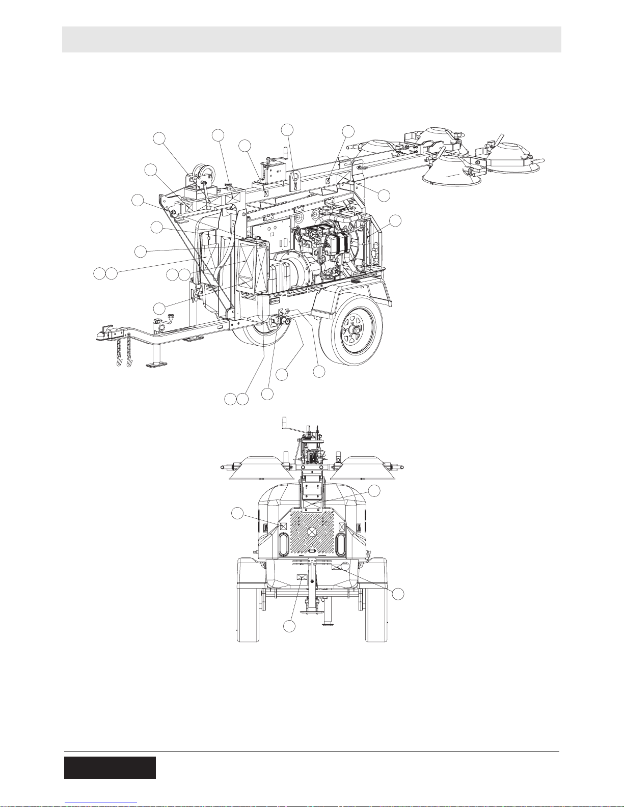
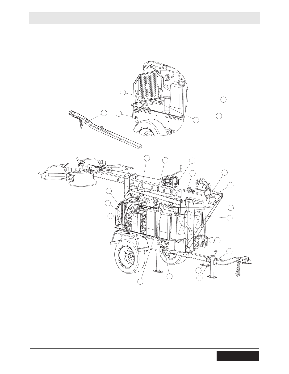
2Labels
2.1 Label Locations
C
B
H
I
G
RT
QS
CC
A
BB
PO
D
Z
AA
BB
E
V
EE
J
X
K
AA
wc_gr007036
16 wc_si000381gb.fm
Page 17
LTN 6L Labels
M
HH
CC
EE
JJ
GG
BB
D
BB
N
J
B
U
V
F
L
H
RS
wc_si000381gb.fm 17
FF
AA
Y
DD
AA
wc_gr007037
Page 18

Labels LTN 6L
2.2 Label Meanings
Wacker Neuson machines use international pictorial labels where
needed. These labels are described below.
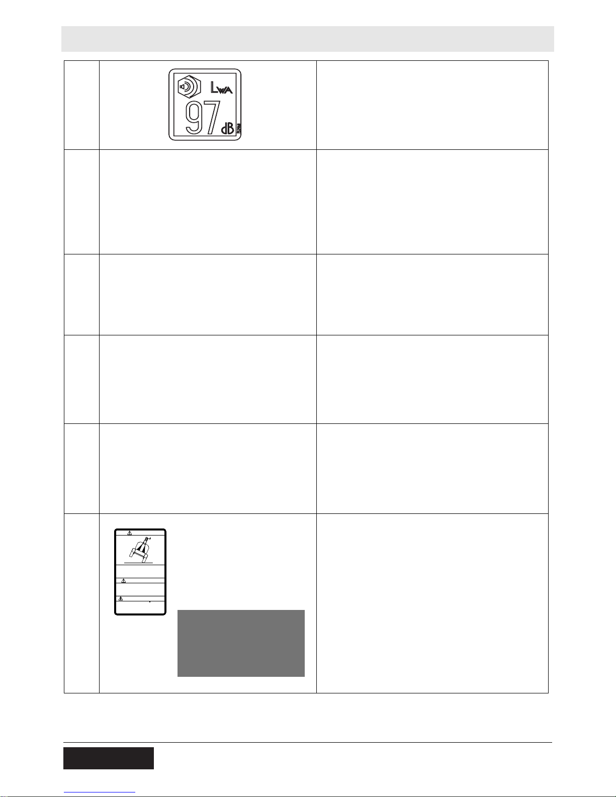
A
B
C
WARNING
Automatic locking pin.
A non-secured, falling tower can cause serious
injury or death if a person is hit. To secure tower,
verify automatic locking pin has been engaged.
WARNING!
Avoid crushing area.
DANGER!
Contact with overhead electrical power lines will
cause serious injury or death. Do not position
Light Tower under electrical power lines.
WARNING!
Completely lower tower BEFORE tilting tower.
Tilting an extended tower can cause serious
injury or death.
18 wc_si000381gb.fm
Page 19
LTN 6L Labels
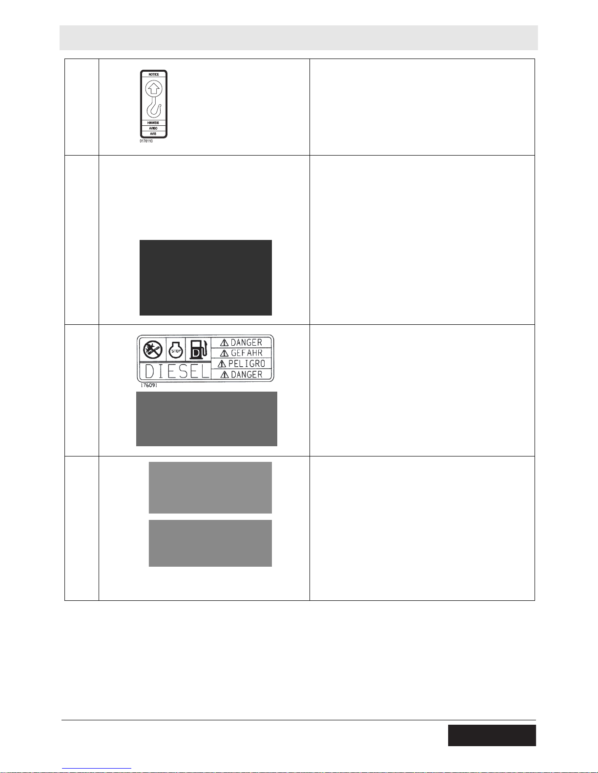
D
E
F
NOTICE
Lifting point.
WARNING!
Secure tower in transport lock before lifting or
towing. A loose swinging tower could cause personal injury or machine damage.
DANGER!
No sparks, flames, or burning objects near
machine. Stop the engine before adding fuel. Use
only diesel fuel.
G
wc_si000381gb.fm 19
DANGER!
Asphyxiation hazard.
Engines emit carbon monoxide.
Do not run the machine indoors or in an
enclosed area unless adequate ventilation,
through such items as exhaust fans or hoses,
is provided.
Read the Operator’s Manual. No sparks,
flames, or burning objects near the machine.
Stop the engine before refueling.
Page 20
Labels LTN 6L
H
I
J
WARNING!
Electric shock and arc flash can cause serious
injury or death. Electrical storage device within.
Contact a qualified electrician for service or to
open electrical box.
WARNING!
Read and understand the supplied Operator’s
Manual before operating the machine. Failure to
do so increases the risk of injury to yourself and
others.
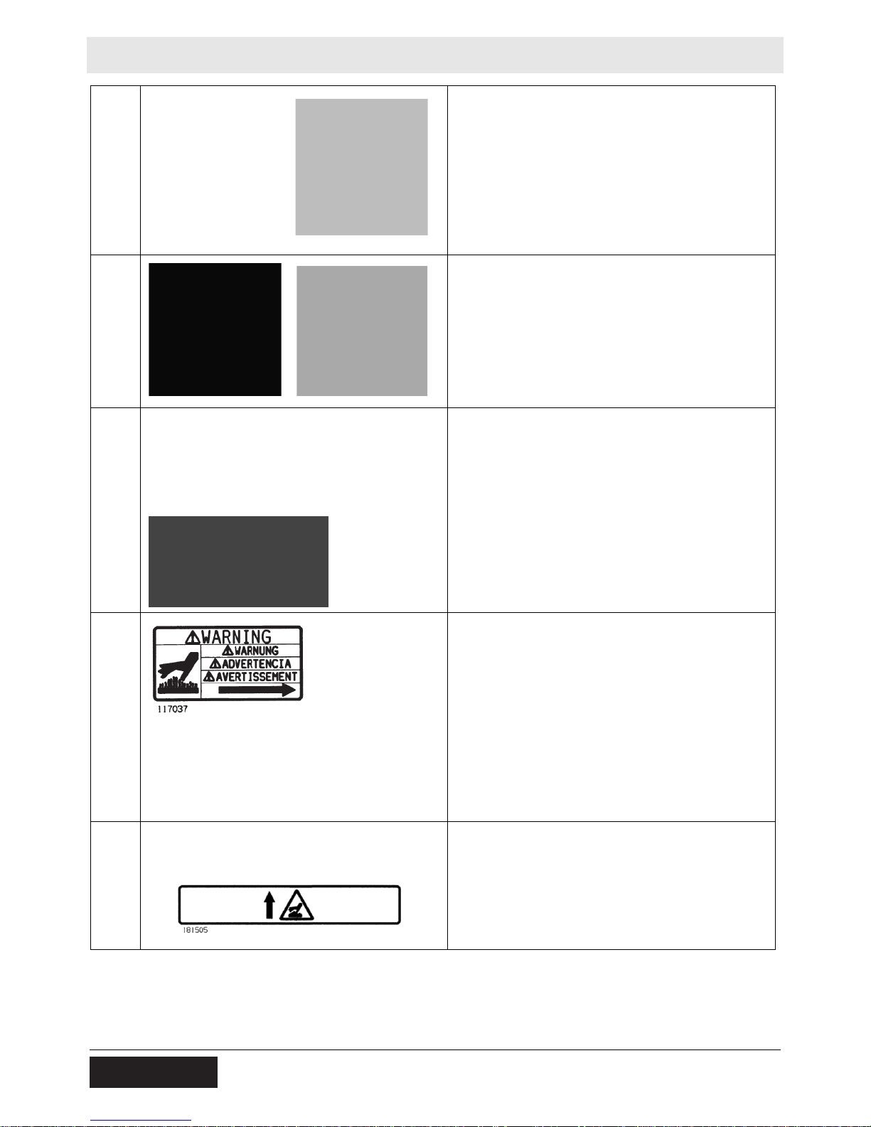
WARNING!
Stand clear of front and rear of machine when
tower is being tilted up or down.
K
L
WARNING!
Hot surface!
WARNING!
Hot surface!
20 wc_si000381gb.fm
Page 21

LTN 6L Labels
M
N
A nameplate listing the model number, item number, revision number, and serial nu mber is
attached to each unit. Please record the information found on this nameplate so it will be available
should the nameplate become lost or damaged.
When ordering parts or requesting service information, you will always be asked to specify the
model number, item number, revision number,
and serial number of the unit.
WARNING!
Ultraviolet radiation from lamp can cause serious
skin and eye irritation. Use only with undamaged
lamps. Use only with provided undamaged lens
cover and fixture.
wc_si000381gb.fm 21
Page 22
Labels LTN 6L
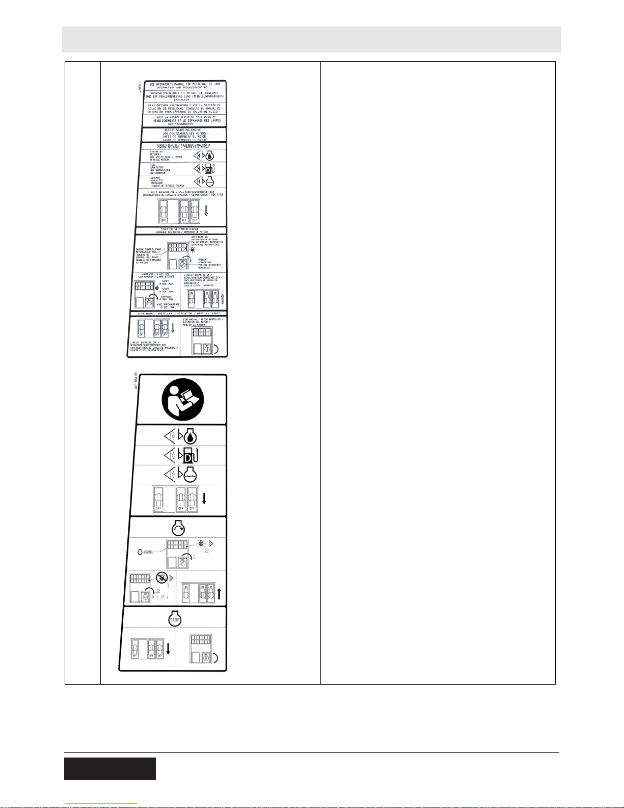
O
See Operator’s Manual for metal halide lamp
information and troubleshooting.
Before starting engine
Check levels of:
Engine oil
Fuel
Coolant
Circuit breakers off
Start engine
Engine control panel
Auto heating
Preheat
Light out
Start, 15 sec. max.
Circuit breakers on
Shut down
Circuit breakers off
Stop engine
22 wc_si000381gb.fm
Page 23
LTN 6L Labels
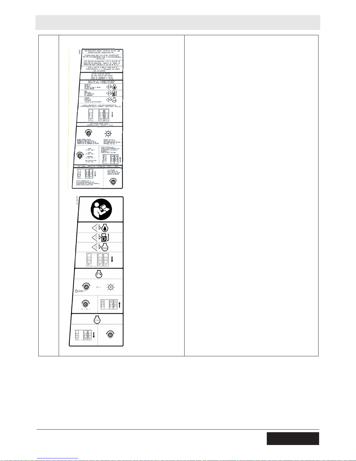
P
See Operator’s Manual for metal halide lamp
information and troubleshooting.
Before starting engine
Check levels of:
Engine oil
Fuel
Coolant
Circuit breakers off
St art engine
Engine control switch
Preheat (30 sec.)
Start, 15 sec. max.
Circuit breakers on
Shut down
Circuit breakers off
Stop engine
wc_si000381gb.fm 23
Page 24
Labels LTN 6L
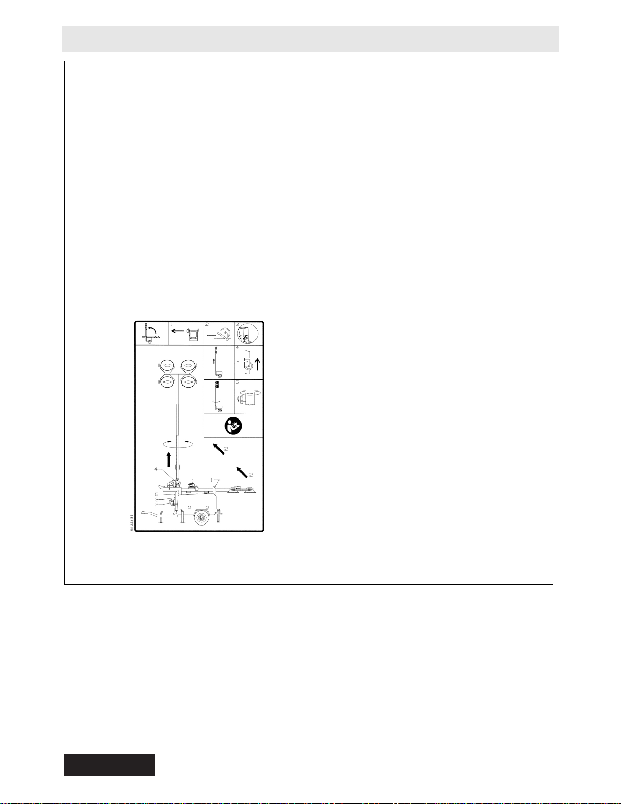
Q
Manual Winch System
To raise tower:
1. Release transport lock.
2. Tilt tower using winch.
3. Tilt tower until automatic locking pin snaps into
place.
To increase height of tower:
4. Raise tower using winch.
To aim lights:
5. Rotate tower and tighten knob.
24 wc_si000381gb.fm
Page 25

LTN 6L Labels
R
Manual Winch System
To lower tower:
1. Turn off all lights and engine.
2. Rotate tower and tighten knob.
3. Lower tower using winch.
To tilt tower for transport:
4. Release and hold spring-loaded pin.
5. Tilt tower using winch.
To secure tower for transport:
6. Insert pin through transport lock and secure
with pin.
7. Position light fixtures down.
wc_si000381gb.fm 25
Page 26
Labels LTN 6L
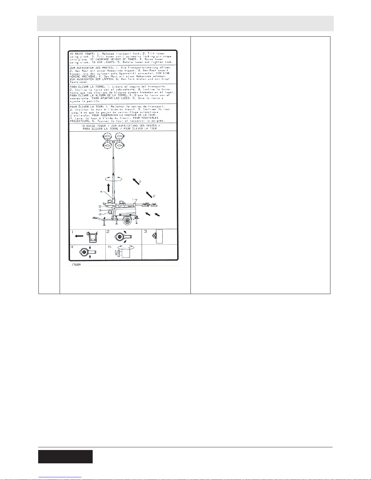
S
Power Winch System
To raise tower:
1. Release transport lock.
2. Tilt tower using winch.
3. Tilt tower until automatic locking pin snaps into
place.
To increase height of tower:
4. Raise tower using winch.
To aim lights:
5. Rotate tower and tighten knob.
26 wc_si000381gb.fm
Page 27
LTN 6L Labels
T
Power Winch System
To lower tower:
1. Turn off all lights and engine.
2. Rotate tower and tighten knob.
3. Lower tower using winch.
To tilt tower for transport:
4. Release and hold spring-loaded pin.
5. Tilt tower using winch.
To secure tower for transport:
6. Insert pin through transport lock and secure
with pin.
7. Position light fixtures down.
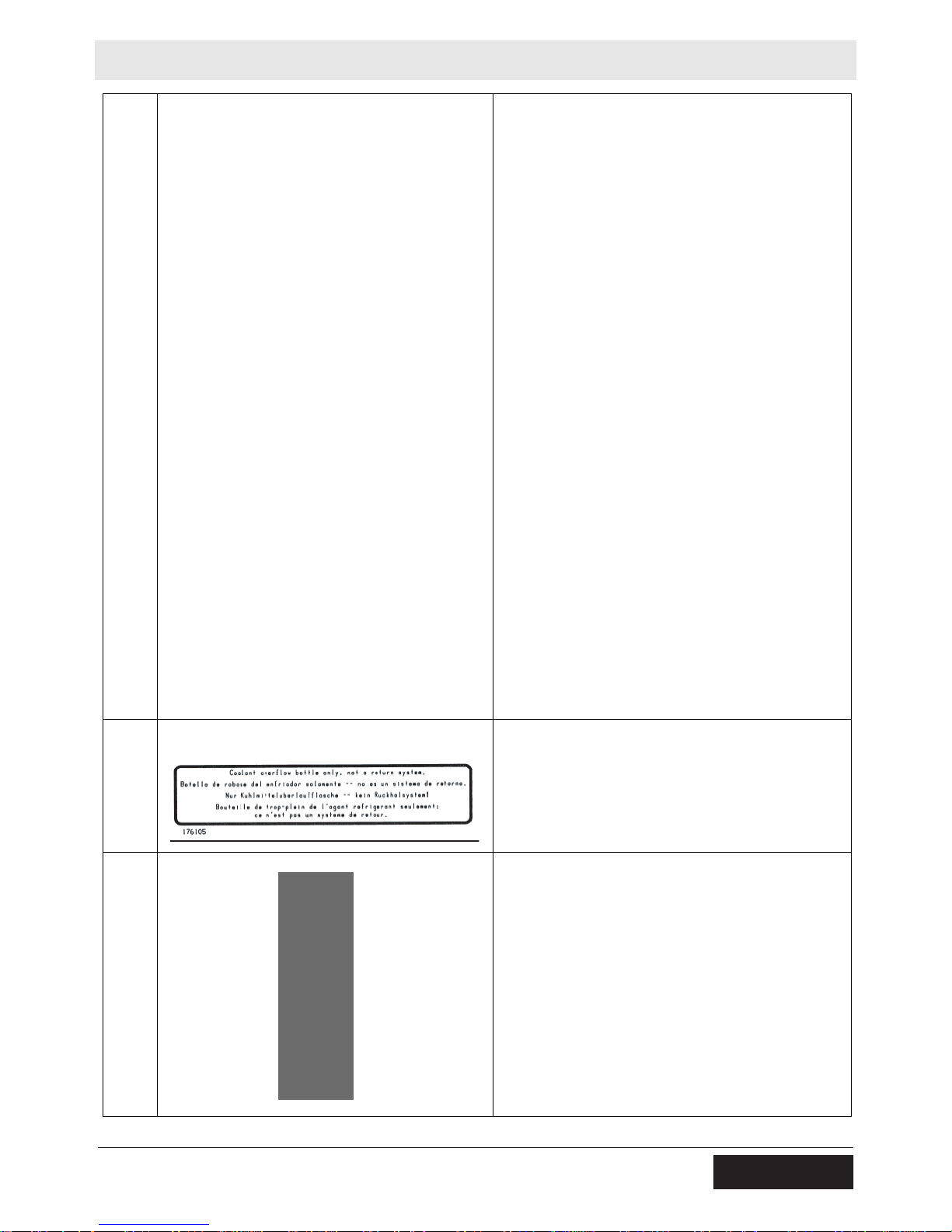
U
V
wc_si000381gb.fm 27
Coolant overflow bottle only, not a return system.
WARNING!
Pinching hazard. Rotating machinery.
Page 28
Labels LTN 6L
Al remolcar, evite altas
velocidades, aceleracion
rapida, y vueltas agudas.
DANGER DE RETORNEMENT
AVERTISSEMENT
ADVERTENCIA
PELIGRO DE VUELCO
Avoid high speeds, rapid
acceleration and sharp turns
when towing.
WARNING
ROLL OVER HAZARD
178647
En remorquant, éé
viter des
vitesses rapides, acceleration
rapide, et virages tranchantes.
X
Y
Z
AA
Guaranteed sound power level in dB(A).
Read Operator’s Manual.
Use hitch rated from trailer’s “Gross Vehicle
Weight Rating”.
Securely attach trailer to tow vehicle.
Attach safety chains using cross pattern.
Attach breakdown chain to vehicle.
Check trailer lights.
Electrical ground
Insert jack locking pin before extending jack.
BB
CC
WARNING
ROLL OVER HAZARD
Avoid high speeds, rapid
acceleration and sharp turns
when towing.
ADVERTENCIA
PELIGRO DE VUELCO
Al remolcar, evite altas
velocidades, aceleracion
rapida, y vueltas agudas.
AVERTISSEMENT
DANGER DE RETORNEMENT
En remorquant,
vitesses rapides, acceleration
rapide, et virages tranchantes.
178647
Fork lift pocket
WARNING
ROLL-OVER HAZARD
To prevent injury or equipment damage, avoid
high speeds and sharp turns when towing.
viter des
28 wc_si000381gb.fm
Page 29
LTN 6L Labels
UTILITY 159116
U.S.PAT.Nos.: 6012285, 6471476,
D416858, D454357 OTHER U.S. AND
FOREIGN PATENTS PENDING
DD
EE
FF
Transport position of the jack
Tie-down point.
Low sulfur fuel or ultra low sulfur fuel only.
GG
JJ
KK
U.S.PAT.Nos.: 6012285, 6471476,
D416858, D454357 OTHER U.S. AND
FOREIGN PATENTS PENDING
UTILITY 159116
This machine may be covered by one or more
patents.
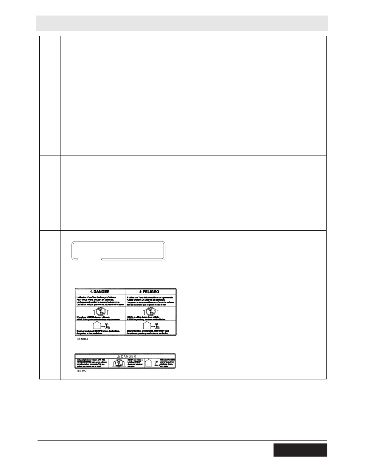
DANGER
Using a light tower indoors CAN KILL YOU IN
MINUTES. Light tower exhaust contains carbon
monoxide. This is a poison you cannot see or
smell.
NEVER use inside a home or garage, EVEN IF
doors and windows are open.
Only use OUTSIDE and far away from windows,
doors, and vents.
wc_si000381gb.fm 29
Page 30
Lifting the Machine LTN 6L
3 Lifting the Machine
3.1 Procedure
See Graphic: wc_gr005415
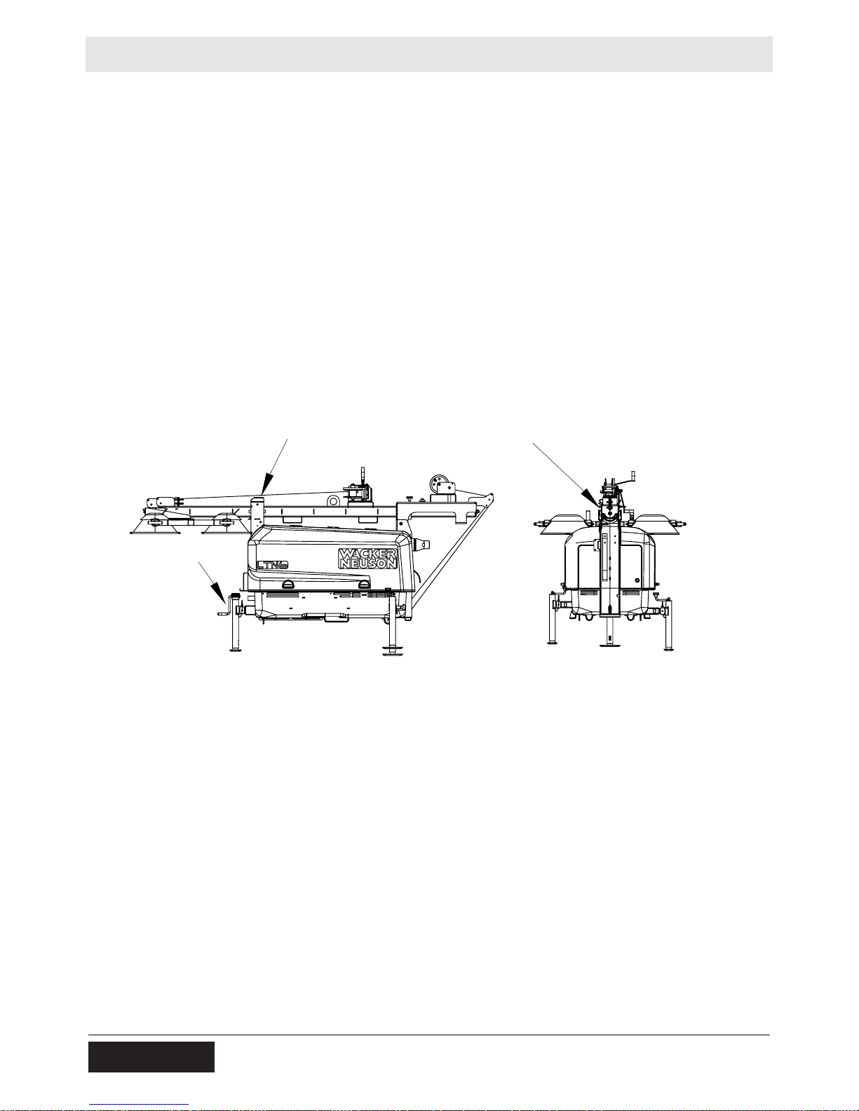
3.1.1 Check that the tower cradle lock pin (a) is in place and secured with
the safety pin.
3.1.2 Ensure that the tower is completely nested inside the transport cradle
and the pin (b) is secure.
3.1.3 Make sure the doors are properly latched.
3.1.4 Return the outriggers to their travel position. Check that the outrigger
bars and jacks are locked in place.
3.1.5 Crank the rear jack (c) all the way in and rotate it 90°.
The Light Tower is now ready to lift.
a
b
c
wc_gr005415
30 wc_tx001375gb.fm
Page 31
LTN 6L Operation
4 Operation
4.1 Locating Trailer
See Graphic: wc_gr005073
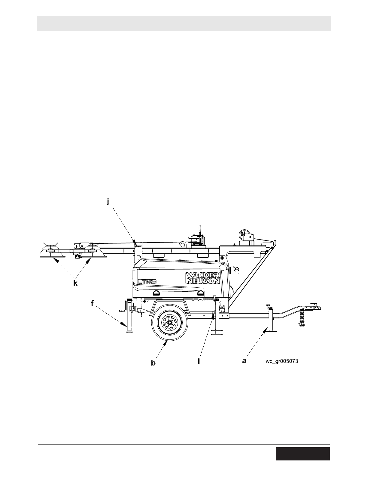
4.1.1 For maximum light coverage locate the Light Tower at ground level or
in a spot higher than the area being lighted.
4.1.2 Position the trailer on a firm, flat surface clear of overhead wires and
obstructions. Be sure that there is enough area for outrigger
extensions to be fully extended.
4.1.3 Connect the ground stud (l) located on the trailer frame to a good
earthen ground. Consult local codes for proper grounding techniques.
The tower extends up to 9 m (30 ft.). Make sure the area above the
trailer is open and clear of overhead wires and obstructions.
WARNING
wc_tx000766gb.fm 31
Page 32

Operation LTN 6L
4.2 Leveling Trailer
See Graphic: wc_gr005073, wc_gr005074
The trailer must be leveled and the outriggers extended before raising
the tower. The outriggers must remain extended while the tower is up.
Failure to level the trailer or extend the outriggers will severely reduce
WARNING
4.2.1 Pull the locking pin on the tongue jack (a) and rotate the tongue jack
4.2.2 Pull the outrigger lock pin (c) to release the outrigger. Pull both
4.2.3 Rotate rear jack (f) down, as shown.
4.2.4 Extend the jack(s) on the highest side(s) of the trailer until they rest
the stability of the unit and could allow the tower to tip and fall.
90° as shown.
Block or chock the trailer wheels (b). Crank the tongue jack down to
raise the trailer tongue off the vehicle.
outrigger extensions (d) out until you feel outrigger lock pin lock back
into place. Rotate jacks (e) down.
firmly on the ground. Extend the remaining jacks until the trailer is
level.
32 wc_tx000766gb.fm
Page 33

LTN 6L Operation
4.3 Adjusting Lights
See Graphic: wc_gr005074
Each light fixture can be aimed up, down, left or right. Position each
fixture by loosening toolless light adjusters (g) and aiming the light up
or down. DO NOT loosen the inside nut (x). Loosening this nut could
cause damage to the light fixture. Loosen the nut (h) to turn light
fixtures left or right. Tighten adjusters and nuts after positioning the
lights.
Always return the light fixtures to aim at the ground when the tower is
in the cradle for towing.
wc_tx000766gb.fm 33
Page 34

Operation LTN 6L
4.4 Preparing Trailer for Towing or Lifting
See Graphic: wc_gr005073, wc_gr005074
4.4.1 Check that the tower cradle lock pin (j) is in place and secured with the
safety pin.
4.4.2 Ensure that the tower is completely nested inside the transport cradle
and the pin (t) is secure.
4.4.3 Make sure the doors are properly latched.
4.4.4 Return the outriggers to their travel position. Check that the outrigger
bars and jacks are locked in place.
4.4.5 Crank the rear jack (f) all the way in and rotate it 90°.
The Light Tower is now ready to lift. Use the designated lift points.
For towing, continue.
4.4.6 Use the tongue jack (a) to raise the trailer tongue up and then lower it
over hitch on towing vehicle. Lock the hitch to coupling and attach the
safety chains. Swivel the tongue jack 90° and lock it in place.
4.4.7 Connect the trailer wiring to the towing vehicle. Check the brake, turn,
and tail lights for proper operation.
4.4.8 Position the light fixtures (k) down. For rough, off-road transportation
remove lamps from fixtures to avoid damage.
4.4.9 Check the tire inflation.
NOTICE: Maximum recommended speed for highway towing is 72
km/hour (45 MPH). Recommended off-road towing speed is not to
exceed 16 km/hour (10 MPH) or less depending on terrain.
34 wc_tx000766gb.fm
Page 35

LTN 6L Operation
4.5 Raising Tower (Manual Winch System)
See Graphic: wc_gr005075
NEVER raise the tower or operate the Light Tower in high winds.
NEVER raise the tower while the engine is running.
WARNING
WARNING
Do not move the Light Tower while it is operating.
HIGH VOLTAGE! DO NOT use the Light Tower if insulation on
electrical cord is cut or worn through. Repair or replace the cord before
using. Bare wires in contact with the metal frame of the trailer or tower
can cause electrocution.
DO NOT position the Light Tower under electrical power lines.
NEVER allow anyone to stand near the rear of the unit while raising the
tower.
WARNING
The Light Tower includes two separate winches—one for lifting the
tower to the vertical position, the other for raising the tower. Each
winch is an automatic brake-type winch that automatically brakes
when the handle is released. The handle must be rotated to wind in the
cable as well as to unwind the cable.
NEVER touch the winch pawl! Releasing the pawl may cause the
tower to fall.
WARNING
4.5.1 Check winch cables (n) for wear or damage, and make sure they are
resting properly in pulleys. Do not use the Light Tower if either winch
cable is damaged.
4.5.2 Remove the cradle locking pin (j) from the cradle.
4.5.3 Check the operation of the tilt winch (o) by rotating the winch handle
1/4-turn clockwise (“cable in” direction). The winch pawl must engage
winch gear teeth. When operating properly, the winch pawl will make
a “clicking” sound when the winch handle is rotated clockwise. Do not
attempt to raise the tower if the winch is damaged or not operating
properly.
Pinching/crushing hazards. Moving parts can crush or cut extremities.
Keep hands and fingers clear of pinch points when raising the tower
WARNING
wc_tx000766gb.fm 35
Page 36

Operation LTN 6L
4.5.4 Continue to rotate the winch handle and raise the tower to the vertical
position until the vertical tower locking pin (p) locks the tower in place.
Be certain the vertical tower locking pin is fully engaged in the locking
position before raising the tower.
NOTICE: While raising the tower, pay close attention to the coil cord
and make sure that it does not tangle or become caught on any part of
the machine.
NEVER pull the vertical tower locking pin (p) while the tower is
raised! Releasing the vertical tower locking pin while the tower is
WARNING
4.5.5 After the tower is in the vertical position, check the operation of the
raised may cause the tower to fall or the machine to tip over.
telescoping winch (q) by rotating the winch handle 1/4-turn clockwise
(“cable in” direction). The winch pawl must engage winch gear teeth.
When operating properly, it will make a “clicking” sound when the
winch handle is rotated clockwise. Do not attempt to raise the tower if
the winch is damaged or not operating properly. Continue rotating the
winch handle until tower is at the desired height. Do not over crank the
winch when the tower is fully extended.
NOTICE: Do not extend the tower beyond the red marking on the
tower!
4.5.6 Once the tower is at the desired height, rotate the tower to the desired
direction. To rotate, loosen rotation locking knob (s). Then rotate the
tower until the lights face the desired direction, and then retighten the
rotation locking knob.
36 wc_tx000766gb.fm
Page 37

LTN 6L Operation
o
wc_tx000766gb.fm 37
Page 38

Operation LTN 6L
4.6 Lowering Tower (Manual Winch System)
See Graphic: wc_gr005075
Be sure to read and understand the operating instructions before
lowering the tower!
If for any reason a part of the tower hangs up or a winch cable develops
slack before tower is fully lowered, stop immediately! Continuing to
WARNING
WARNING
turn the winch handle will increase the slack in the cable. Too much
slack could cause the tower to collapse should it suddenly free up. If
the tower hangs up, level the trailer. Slightly shake or twist the tower
assembly to free the bind. Contact an authorized Wacker Neuson
service representative immediately.
NEVER lower the tower while the unit is operating.
NEVER allow anyone to stand near the rear of the unit while lowering
the tower.
WARNING
4.6.1 Turn the lights off. Shut down the engine.
NOTICE: Shutting down the engine before turning off the lights could
damage floodlight ballasts or generator capacitor(s).
NOTICE: Observe power cord while lowering the tower. Make sure the
coiled cord is not damaged during the lowering process.
4.6.2 Lower the tower by turning the handle on the telescoping winch (q)
counterclockwise (“cable out” direction).
NEVER touch the winch pawl! Releasing the winch pawl may cause
the tower to fall.
WARNING
4.6.3 Loosen the rotation locking knob (s) and rotate the tower so the
winches are facing toward the trailer tongue.
38 wc_tx000766gb.fm
Page 39

LTN 6L Operation
4.6.4 Pull and hold the tower locking pin (p). Rotate the handle on the tilt
winch (o) counterclockwise (“cable out” direction) until the tower spring
begins to pivot the tower down. Release the tower locking pin and
continue to rotate the handle until the tower is resting in the transport
cradle. Be sure that the secondary locking pin (t) penetrates all
sections of the tower.
NEVER pull the vertical tower locking pin (e) while the tower is
raised! Releasing the locking pin while the tower is raised may cause
WARNING
4.6.5 After the tower is down, secure it in the cradle by inserting the cradle
4.6.6 Position the light fixtures to aim at the ground.
the tower to fall or the machine to tip over.
lock pin (j). Insert the clip through the pin to secure it in place.
NOTICE: Allow the floodlights to cool 10–15 minutes before moving
trailer. Moving the trailer while the lights are still hot could cause the
lamps to break.
wc_tx000766gb.fm 39
Page 40

Operation LTN 6L
4.7 Raising Tower (Power Winch System)
See Graphic: wc_gr005076
ALWAYS observe the tower while raising and lowering the tower.
NEVER raise the tower or operate the Light Tower in high winds.
WARNING
NEVER raise the tower while the engine is running.
Do not move the Light Tower while it is operating.
HIGH VOLTAGE! DO NOT use Light Tower if insulation on electrical
cord is cut or worn through. Repair or replace cord before using. Bare
WARNING
wires in contact with the metal frame of the trailer or the Light Tower
can cause electrocution.
DO NOT position the Light Tower under electrical power lines.
NEVER allow anyone to stand near the rear of the unit while raising the
tower.
WARNING
The Light Tower includes two separate winches—one for lifting the
tower to the vertical position, the other for raising the tower.
4.7.1 Check the winch cables (n) for wear or damage, and make sure they
are resting properly in the pulleys. Do not use the Light Tower if either
winch cable is damaged.
4.7.2 Remove the cradle locking pin (j) from the cradle.
4.7.3 Check the operation of the tilt winch (o). Turn the vertical rotary switch
(v) on the control panel to the up position. Do not attempt to raise the
tower if the winch is damaged or not operating properly.
NOTICE: Continuous running of the winch in excess of 4 minutes will
damage the winch motor.
Note: It is normal for smoke to be produced during the first few
operations of a new power winch.
4.7.4 Hold the switch in the up position and raise the tower to the vertical
position until the vertical tower locking pin (p) locks the tower in place.
Be certain the vertical tower locking pin is fully engaged in the locking
position before raising the tower.
NEVER pull the vertical tower locking pin (p) while the tower is
raised! Releasing the vertical tower locking pin while tower is raised
may cause the tower to fall or the machine to tip over.
WARNING
40 wc_tx000766gb.fm
Page 41

LTN 6L Operation
4.7.5 After the tower is in the vertical position, check the operation of the
telescoping winch (q). Turn the telescope rotary switch on the control
panel to the up position. Do not attempt to raise the tower if the winch
is damaged or not operating properly. Continue to hold switch in the up
position until tower is at the desired height. Release switch when tower
is fully extended.
NOTICE: Continuous running of the winch in excess of 4 minutes will
damage the winch motor.
NOTICE: Do not extend tower beyond red marking on tower!
4.7.6 Once the tower is at the desired height, rotate the tower to the desired
direction. To rotate, loosen rotation locking knob (s). Then rotate the
tower until the lights face the desired direction and retighten the
rotation locking knob.
wc_tx000766gb.fm 41
Page 42

Operation LTN 6L
4.8 Lowering Tower (Power Winch System)
See Graphic: wc_gr005076
ALWAYS observe the tower while raising and lowering the tower.
Be sure you read and understand the operating instructions
WARNING
WARNING
WARNING
before lowering the tower!
If for any reason any part of the tower hangs up or the winch cable
develops slack before the tower is fully lowered, stop immediately!
Continuing to power the winch will increase slack in the cable. Too
much slack could cause tower to collapse should it suddenly free up.
If the tower hangs up, level the trailer. Slightly shake or twist the tower
assembly to free the bind. Contact an authorized Wacker Neuson
service representative immediately.
NEVER lower the tower while the unit is operating.
NEVER allow anyone to stand near the rear of the unit while lowering
the tower.
WARNING
4.8.1 Turn the lights off. Shut down the engine.
NOTICE: Shutting down the engine before turning off the lights could
damage the floodlight ballasts or the generator capacitor(s).
NOTICE: Observe the power cord while lowering the tower. Make sure
the coiled cord is not damaged during the lowering process.
4.8.2 Lower the tower by turning and holding the telescope rotary switch on
the control panel in the down position.
NOTICE: Continuous running of the winch in excess of 4 minutes will
damage the winch motor.
Note: It is normal for smoke to be produced during the first few
operations of a new power winch.
4.8.3 Loosen the rotation locking knob (s) and rotate the tower so the lights
face the rear of the trailer and the winches are facing toward the trailer
tongue.
42 wc_tx000766gb.fm
Page 43

LTN 6L Operation
4.8.4 Pull and hold the tower locking pin (p). Turn and hold the vertical rotary
switch (v) on the control panel in the down position until the tower is
resting in the transport cradle. Be sure that the secondary locking pin
(t) penetrates all sections of the tower.
NOTICE: Continuous running of the winch in excess of 4 minutes will
damage the winch motor.
NEVER pull the vertical tower locking pin (e) while the tower is
raised! Releasing the vertical tower locking pin while the tower is
raised may cause the tower to fall or the machine to tip over.
WARNING
4.8.5 After the tower is down, secure it in the cradle by inserting the cradle
lock pin (j). Insert the clip through the pin to secure it in place.
4.8.6 Position the light fixtures to aim at the ground.
NOTICE: Allow the floodlights to cool 10–15 minutes before moving
the trailer. Moving the trailer while the lights are still hot could cause
lamps to break.
4.9 Emergency Crank Handle (Power Winch System)
An emergency crank handle is provided for use in the event of a power
failure.
4.9.1 Remove the electrical power from the winch.
4.9.2 Remove the plug from the side of the winch cover. Insert the handle so
that it completely engages with the drive shaft. The handle can be
cranked in either direction.
4.9.3 Always remove the handle from the winch after use and replace the
plug.
NEVER operate the winch electrically with the emergency crank
handle in position.
WARNING
wc_tx000766gb.fm 43
Page 44
Operation LTN 6L
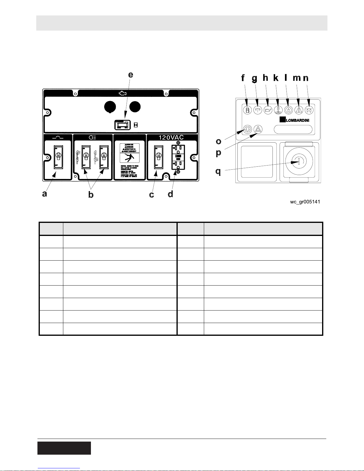
4.10 Control Panels (Manual Winch System)
Floodlight Control Panel Engine Control Panel
Ref. Description Ref. Description
a 50 Amp circuit breaker k High coolant temperature shutdown
b 30 Amp lights circuit breaker l Alternator indicator
c 20 Amp GFI circuit breaker m Auxiliary lights (not used)
d 20 Amp GFI receptacle n Glow plug indicator
e Hour meter o Air filter restriction indicator
f Low fuel indicator (not used) p Auxiliary lights (not used)
g Safety shutdown indicator q Key access door
h Low oil pressure shutdown
44 wc_tx000766gb.fm
Page 45

LTN 6L Operation
WARNING
WARNUNG
ADVERTENCIA
AVERTISSEMENT
NEUTRAL BONDED TO FRAME
CONDUCTOR NEUTRO
CONECTADO AL CHASIS
CONDUCTEUR NEUTRE MIS
A LA MASSE DU CHASSIS
NULL-LEITER AM RAHMEN
ANGESCHLOSSEN
4.11 Control Panels (120/240, Manual Winch System)
Floodlight Control Panel Engine Control Panel
r
WARNING
WARNUNG
ADVERTENCIA
AVERTISSEMENT
NEUTRAL BONDED TO FRAME
NULL-LEITER AM RAHMEN
ANGESCHLOSSEN
CONDUCTOR NEUTRO
CONECTADO AL CHASIS
CONDUCTEUR NEUTRE MIS
A LA MASSE DU CHASSIS
wc_gr006329
Ref. Description Ref. Description
a 25 Amp circuit breaker k High coolant temperature shutdown
b 30 Amp lights circuit breaker l Alternator indicator
c 20 Amp GFI circuit breaker m Auxiliary lights (not used)
d 20 Amp GFI receptacle n Glow plug indicator
e Hour meter o Air filter restriction indicator
f Low fuel indicator (not used) p Auxiliary lights (not used)
g Safety shutdown indicator q Key access door
h Low oil pressure shutdown r 30 Amp receptacle
wc_tx000766gb.fm 45
Page 46

Operation LTN 6L
4.12 Control Panels (Power Winch System)
Floodlight Control Panel Engine Control Panel
Ref. Description Ref. Description
a 50 Amp circuit breaker l Alternator indicator
b 30 Amp lights circuit breaker m Auxiliary light (not used)
c 20 Amp GFI circuit breaker n Glow plug indicator
d 20 Amp GFI receptacle o Air filter restriction indicator
e Hour meter p Auxiliary light (not used)
f Low fuel indicator (not used) q Key access door
g Safety shutdown indicator v
h Low oil pressure shutdown w
k High coolant temperature shutdown
Tilt rotary switch
Telescope rotary switch
46 wc_tx000766gb.fm
Page 47

LTN 6L Operation
4.13 Starting
See Graphic: wc_gr005140, wc_gr006328, wc_gr005141, wc_gr005142
4.13.1 Check engine oil, fuel and coolant levels.
Note: If fuel tank was drained or run dry it may be necessary to bleed
fuel lines. Refer to engine operator’s manual.
4.13.2 Check condition of electrical cable on tower. Do not start generator if
insulation on cable is cut or worn through.
4.13.3 Check that the circuit breakers (a, b, c) are in their off position.
NOTICE: Starting engine under load will damage the machine.
4.13.4 On machines equipped with the Lombardini engine, turn key (q) one
click right. Glow plug indicator (n) will illuminate until engine is properly
preheated. This is an automatic timer based on engine temperature.
Crank engine immediately after glow plug light goes off.
4.13.5 Turn key (q) to the start position and hold until engine starts. Release
key after engine starts.
NOTICE: Do not crank engine longer than 10 seconds. This could
cause starter motor to overheat. Return switch to the off position and
wait 15-30 seconds for starter motor to cool down before attempting to
preheat and restart.
Note: If oil pressure is not obtained within 30 seconds after key is
turned to “RUN”, the automatic shutdown system will shut off the fuel
supply. You must return the key to the off position to restart the 30-
second timer before attempting to restart the engine.
4.13.6 Allow engine to warm up before operating the floodlights.
NOTICE: Never use starting fluids to aid in starting of engine.
4.14 Manual Shutdown
To manually stop the machine in the event of an emergency:
4.14.1 Shut off the main circuit breaker.
4.14.2 Turn the starting key to the “off” (O) position.
4.15 Automatic Shutdown
This unit is equipped with a low oil, high temperature auto-shutdown
system. This system will automatically shut off the fuel supply to the
engine if the oil pressure drops too low or the engine exceeds normal
operating temperatures. Return the key switch to the off position to
reset the unit after an engine shutdown.
wc_tx000766gb.fm 47
Page 48

Operation LTN 6L
4.16 Operating Lights
See Graphic: wc_gr005140, wc_gr006328, wc_gr005141, wc_gr005142
Turn on the main circuit breaker (a) first, then turn on each light circuit
breaker (b), one at a time.
Metal halide floodlights require a warm-up time of 5–15 minutes before
they reach full output. If the floodlights are shut down, a 10-minute
cool-down period is required before turning them back on.
4.17 Stopping
See Graphic: wc_gr005140, wc_gr006328, wc_gr005141, wc_gr005142
4.17.1 Turn the circuit breakers (a, b, c) off and remove any other loads from
the generator.
NOTICE: Never shut down the engine without turning off the lights.
Damage to the generator will occur.
4.17.2 Turn the key (q) to the off position.
4.18 Derating
All generator sets are subject to derating for altitude and temperature.
Although derating should not affect operation of the floodlights, it will
reduce the available reserve power to the receptacle.
Ratings are typically reduced 3% per 300 m (1000 feet) elevation from
sea level, and 2% per 10°F (5.5°C) increase in ambient temperature
above 78°F (25°C).
48 wc_tx000766gb.fm
Page 49

LTN 6L Operation
4.19 Receptacle
See Graphic: wc_gr005140, wc_gr006328, wc_gr005141
The control panel is equipped with a convenience receptacle for
running accessories and tools from the generator. Power to this
receptacle is available any time the engine is running and the circuit
breaker is on.
NOTICE: Do not draw more than 1660 Watts from the receptacle with
all of the lights on or the lights will turn off.
A circuit breaker (c) protects the Ground Fault Interrupt (GFI)
receptacle (d). The GFI receptacle should be tested for proper
operation each time it is used.
To test a GFI:
Push the test button in. The reset button should pop out. Power to the
receptacle is now off. To restore power to receptacle, push reset
button in.
NOTICE: If the reset button does not pop out, the GFI is defective. Do
not use the receptacle until the problem can be corrected.
If the reset button pops out during use, check the generator and
attachments for defects.
wc_tx000766gb.fm 49
Page 50

Factory Installed Options LTN
5 Factory Installed Options
This machine may be equipped with one or more of the following factory-installed
options. To verify if any of these options are installed on your machine, contact
Wacker Neuson Corporation at 1-800-770-0957. A nameplate listing the Model
Number, Item Number, Revision, and Serial Number is attached to each unit.
Please have this information available when contacting Wa cker Neuson
Corporation.
The illustrations shown in this chapter represent typical installations. The factoryinstalled options on your machine may look different.
5.1 Block Heater
The engine block heater option includes a block heater (a) with a cord (b).
The function of the block heater is to heat the engine coolant/ engine block
to improve cold-weather engine starting. Plug the cord into a 120V power
supply.
a
b
wc_gr006975
50 wc_tx001650gb.fm
Page 51

LTN Factory Installed Options
5.2 Battery Blanket
An electrically powered blanket (a) warms the battery while the machine is not in
use. The blanket eliminates engine starting difficulties caused by a cold, frozen, or
discharged battery. Plug the cord into a 120V power supply.
a
wc_gr007422
5.3 Oil Pan Heater
Cold, thick engine oil does not flow freely and may cause engine starting
difficulties. An oil pan heater installed on the engine oil pan keep s the oil warm and
flowing. Heat from this electrical device warms the supply of engine oil contained in
the pan while the machine is not in use. Plug the cord into a 120V power supply.
wc_tx001650gb.fm 51
Page 52

Maintenance LTN 6L
6 Maintenance
6.1 Periodic Maintenance Schedule
The table below lists basic machine maintenance. Tasks designated
with check marks may be performed by the operator. Tasks
designated with square bullet points require special training and
equipment.
Check for fluid leaks.
Check engine oil.
Check fuel level.
Replace air filter if indicator light is on.*
Change engine oil.**
Check level of battery electrolyte.
Check condition and tension on fan belt.
Check condition of radiator hoses.
Replace oil filter.*
Replace fuel filter.
Flush radiator.
Before
each
use
3
3
3
Every
125
hours
Every
250
hours
Every
500
hours
Every
1000 hours
or two years
Replace fan belt.
Check valve clearance.
Remove sediment in fuel tank.
Change radiator coolant.
Replace battery.
Replace radiator hoses and clamps.
Replace fuel pipes and clamps.
* Replace air filter after air filter restriction switch indication or one year. Lombardini does not rec-
ommend the removal of air filter elements for purposes of inspection.
** Change engine oil and filter after first 50 hours of operation.
52 wc_tx000767gb.fm
Page 53

LTN 6L Maintenance
2
GN
WH
GN
BL
4
WH
BL
GN
WH
GN
BL
1
WH
3
BL
6.2 Installing / Removing Light Fixtures
See Graphic: wc_gr005376
Always turn off light circuit breakers and shut down engine before
disconnecting light fixtures or changing lamps.
WARNING
Remove fixtures by disconnecting electrical cords at the junction box
(b). Remove nuts (c) from fixture mounting brackets and remove both
fixture and bracket off stud.
NOTICE: Only a trained technician should be allowed to install and
remove fixture wiring.
.
Lamps become extremely hot in use! Allow lamp and fixture to cool
10-15 minutes before handling.
WARNING
Numbering Sequence of Floodlights Junction Box Wiring for Floodlights
GN
BL
WH
1
GN
BL
3
WH
GN
BL
WH
GN
BL
WH
wc_gr005376
2
4
Wire Colors
BK Black RD Red YL Yellow OR Orange
GN Green TN Tan BR Brown PU Purple
BU Blue VIO Violet CL Clear SH Shield
PK Pink WH White GY Gray LB Lt. blue
wc_tx000767gb.fm 53
Page 54

Maintenance LTN 6L
6.3 Replacing / Removing Lamps
Prerequisites
• Engine shut down
• Light circuit breakers turned OFF
• Lamps and fixtures cool to the touch
• Eye protection and gloves
WARNING
Burn hazard. Lamps become extremely hot in use.
f Allow lamps and fixtures to cool 10–15 minutes before handling.
WARNING
Personal injury hazard. Ultraviolet radiation from the lamps can cause serious skin
and eye irritation.
f Use only undamaged lamps.
f Use the lamps only with undamaged original equipment lenses and fixtures.
WARNING
Explosion hazard. Grease or oil residue on the lamp can cause the outer jacket to
burst or shatter. Hot flying glass particles can cause personal injury, property damage, burns, or fire.
f
Do not operate the lights with a lens that is cracked, damaged, or missin g.
f Do not scratch the lamp or subject the lamp to excess pressure.
f Wear eye protection and gloves when removing or replacing lamps.
Follow the procedures below to remove and install the lamp.
Removing the lamp
6.3.1 Remove the screws
(a)
securing the flange rings
(b)
and remove the
flange rings.
c
e
d
b
a
f
wc_gr005881
54 wc_tx000767gb.fm
Page 55

LTN 6L Maintenance
6.3.2 Remove the lens (c) with the gasket (d) attached.
6.3.3 Remove the hardware securing one side of the lamp stabilizer (e).
Once removed, swing the lamp stabilizer to the side and unscrew the
lamp (f).
Installing the lamp
6.3.4 Screw the lamp in firmly, but not forcibly, to minimize loosening due to
vibration. Secure it with the lamp stabilizer.
6.3.5 Install the gasket around the lens and secure the lens to the reflector
with the flange rings and screws.
6.4 Daily Inspection
6.4.1 Check for fluid leaks. Check fluid levels.
6.4.2 Inspect condition of electrical cords. Do not use Light Tower if
insulation is cut or worn through.
6.4.3 Check that winch cables are in good condition. Do not use a cable that
is kinked or starting to unravel.
6.4.4 Check that the vertical tower locking pin and its spring are secured,
aligned, and operating properly.
wc_tx000767gb.fm 55
Page 56

Maintenance LTN 6L
6.5 Air Cleaner
See Graphic: wc_gr000540
Replace the air filter cartridge when the indicator mounted on the
control panel illuminates.
6.5.1 Open air cleaner and remove element.
6.5.2 To clean the filter, lightly tap on a hard surface to eliminate all excess
dirt. Do not blow the paper filter element with compressed air to clean.
Clean the filter cover and support carefully.
6.5.3 Reassemble the filtering element and air cleaner.
6.6 Engine Oil
See Graphic: wc_gr005394
Drain the oil while the engine is still warm.
Note: In the interests of environmental protection, place a plastic sheet
and a container under the machine to collect any liquid which drains
off. Dispose of this liquid in accordance with environmental protection
legislation.
6.6.1 Locate the oil drain hose and remove the plug from the end of the hose.
6.6.2 Allow the oil to drain.
6.6.3 Re-install the oil drain plug.
6.6.4 Remove the oil filter cap and fill the engine crankcase through the oil
filler opening, to the upper mark on the dipstick. See Technical Data
for oil quantity and type.
6.6.5 Re-install the oil filter cap.
wc_gr000540
wc_gr005394
56 wc_tx000767gb.fm
Page 57

LTN 6L Maintenance
6.7 Troubleshooting
HIGH VOLTAGE! This unit uses high voltage circuits capable of
causing serious injury or death. Only a qualified electrician should
troubleshoot or repair electrical problems occurring in this equipment.
WARNING
Problem / Symptom Reason Remedy
Lamp will not light Lamp is too hot. Allow lamp to cool 10–15 minutes
before restarting.
Faulty lamp connection Check that lamp is tight in socket.
Check connections inside connection
boxes on light fixtures and tower.
Plug connection at fixture
is loose or damaged
Lamp broken or burned
out
Circuit breaker turned on Turn off circuit breaker.
Circuit breaker loose or
defective
Generator output incorrect Check incoming voltage to ballast.
Low or no ballast output With the fixture cord removed from its
Have a licensed electrician repair or
replace the plug connection.
Check for:
• broken arc tube or outer lamp jacket
• broken or loose components in lamp
envelope
• blackening or deposits inside lamp
tube.
Have a licensed electrician repair or
replace the circuit breaker.
Incoming voltage should be 120V ± 5V.
If voltage is incorrect, engine speed
may need to be adjusted or generator
may require service.
receptacle, the voltage should measure
400 to 445 VAC. If proper voltage is no t
achieved, perform capacitor check to
determine if capacitor or coil needs to
be replaced.
Low light output Lamp degraded Replace lamp due to normal lamp life.
Low ballast output Check ballast for proper voltage output.
Fixture or lens dirty Clean reflective surface inside fixture
wc_tx000767gb.fm 57
and both inside and outside surface of
glass lens.
Page 58

Technical Data LTN 6L
7 Technical Data
7.1 Engine
Engine Power Rating
Net power rating per ISO 3046 IFN. Actual power output may vary due
to conditions of specific use.
Item Number:
LTN 6L
Engine
Make Lombardini
Model LDW1003
Type 3-cylinder, 4-cycle, liquid-cooled diesel
Max. power rating @
rated speed
Operating speed
(no-load)
Alternator
Battery
Air cleaner
Fuel
Fuel tank capacity
kW (Hp)
rpm
V / A / W
V/Ah/CCA
type
type
l (gal.)
10.0 (13.4) @ 1800 rpm
1800
12 / 45 / 540
12 / 650
Dry-type element
No. 2 diesel
123 (32.5)
Fuel consumption
Running time
Coolant capacity
Oil capacity
l (gal.) / hr.
hours
l (qts.)
l (qts.)
1.71 (0.45)
67
4.7 (5.0)
2.4 (2.5)
58 wc_td000230gb.fm
Page 59

LTN 6L Technical Data
7.2 Generator
Item Number:
LTN 6L
0620297 0620117
0620550 0620553
0620554 0620561
Generator
Frequency
Continuous output
Output
Amps
Hz
kW
volts/
phase
60 ± 2
6.0
120, 1Ø 120/240, 1Ø
A
50
Excitation type Capacitor / Brushless
Power factor 1.0
Voltage regulation
- no load to full load
Speed (no-load)
%
rpm
± 6.0
1800
LTN 6L
0620727
7.3 Machine
Item Number:
Machine
Operating weight (GVWR)
Travel Dimensions
(l x w x h)
Height - tower extended
kg(lbs.)
mm
(in.)
m (ft.)
4600 x 1500 x 1900
(180.4 x 59.3 x 73.2)
Lighting system (1000W) 4
Ballast Coil and core
Max. lighting coverage
@ 0.5 ft. candles
Sound level at 7 m (23 ft.)
Tires
m
(acres)
dB(A)
size
2
Metal Halide - 30,400 (7.52)
LTN 6L
768 (1693)
9 (30)
67
ST175 / 80D13
wc_td000230gb.fm 59
Page 60

Schematics LTN 6L
14 BK/OR
1 BK 8 AWG
8 WH 10 AWG
9 WH 10 AWG
2
4
1
3
GN/YL 12 AWG
CONTROL PANEL
GROUND
12 GN/YL
12 AWG
1
2
11 GN/YL 12 AWG
10 WH 10 AWG
3
4
13 OR
-
+
2 BK 10 AWG
3 BK
10 AWG
4 BK 10 AWG
1 BK 8 AWG
15 BK 10 AWG
7 BK 10 AWG
6 BK 10 AWG
2
GN
WH
GN
BL
4
PU
WH
BL
WH
BL
d
d
m
l
m
l
m
l
m
l
b
i
b
e
g
f
f
c
n
a
j
h
b
k
14 BK/OR
13 OR
4
BK
RD
GN
WH
GN
BL
1
OR
WH
BR
3
BL
YL
GN
2
YL
YL
BK/YL
1
YL
YL
3
BK/YL
11 GN/YL 12 AWG
5 BK
10 AWG
10 WH 10 AWG
BK/YL
YL
YL
WH
PU
8 WH 10 AWG
YL
BK/YL
YL
7 BK 10 AWG
9 WH 10 AWG
BR
OR
6 BK 10 AWG
8 Schematics
8.1 Electrical Schematic
CONTROL PANEL
GROUND
GN/YL 12 AWG
14 BK/OR
9 WH 10 AWG
8 WH 10 AWG
1 BK 8 AWG
12 AWG
11 GN/YL 12 AWG
2
4
1
3
10 WH 10 AWG
b
j
1
2
3
a
4
13 OR
-
h
+
wc_gr005366
n
k
13 OR
14 BK/OR
11 GN/YL 12 AWG
3 BK
10 AWG
4 BK 10 AWG
2 BK 10 AWG
1 BK 8 AWG
c
f
f
g
e
10 WH 10 AWG
15 BK 10 AWG
5 BK
10 AWG
7 BK 10 AWG
6 BK 10 AWG
12 GN/YL
i
ddd
2
4
m
BL
WH
WH
GN
GN
BL
BL
WH
PU
BL
GN
BL
WH
1
ddd
WH
3
GN
BK
RD
YL
OR
BR
m
m
m
4
l
2
l
GN
1
l
3
l
PU
BK/YL
WH
YL
YL
BK/YL
YL
YL
YL
YL
BK/YL
BK/YL
YL
YL
60 wc_tx000936gb.fm
b
8 WH 10 AWG
6 BK 10 AWG
9 WH 10 AWG
7 BK 10 AWG
OR
b
BR
Page 61
LTN 6L Schematics
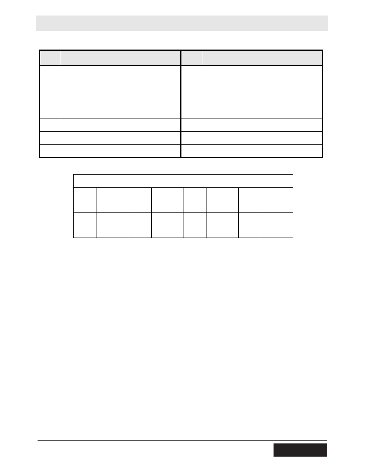
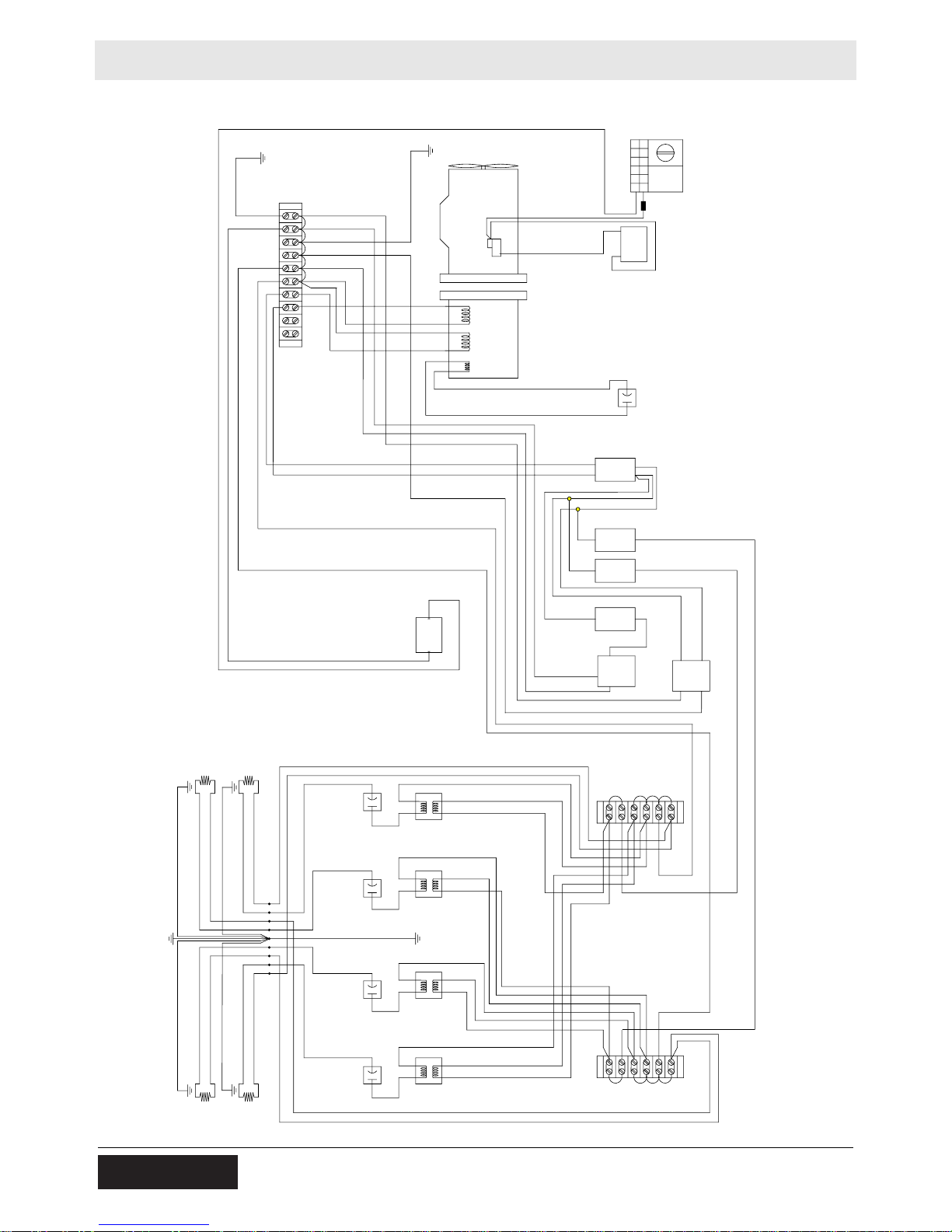
Ref. Description Ref. Description
a Generator h Battery
b Terminal strip i Engine control panel
c Main circuit breaker, 50 Amp j Engine
d Floodlights k Hour meter
e Receptacle, 120V l Transformers
f Circuit breaker, 30 Amp m Capacitors, 24 mF
g Circuit breaker, 20 Amp n Capacitor, 25 mF
Wire Colors
BK Black RD Red YL Yellow OR Orange
GN Green TN Tan BR Brown PU Purple
BU Blue VIO Violet CL Clear SH Shield
PK Pink WH White GY Gray LB Lt. blue
wc_tx000936gb.fm 61
Page 62
Schematics LTN 6L
d
d
m
l
k
m
l
m
l
m
l
b
e
o
g
c
f
f
h
n
a
j
i
b
b
14 BK/OR
1 BK 10 AWG
8 WH 10 AWG
9 WH 10 AWG
2
4
3
1 GN/YL 12 AWG
12 GN/YL
12 AWG
1
2
11 GN/YL 12 AWG
10 WH 10 AWG
3
4
13
-
+
2 BK 10 AWG
4 BK 10 AWG
1 BK 10 AWG
15 BK 10
7 BK 10 AWG
6 BK 10 AWG
2
GN
W
GN
BL
4
PU
W
BL
W
BL
14
13
4
BK
RD
GN
W
GN
BL
1
OR
W
BR
3
BL
YL
GN
2
YL
YL
BK/YL
1
YL
YL
3
BK/YL
11 GN/YL 12 AWG
5 BK
10 AWG
10 WH 10 AWG
BK/YL
YL
YL
W
PU
8 WH 10 AWG
YL
BK/YL
YL
7 BK 10 AWG
9 WH 10 AWG
BR
OR
6 BK 10 AWG
17 BK 10
22 GN/YL 10 AWG
22 GN/YL 10 AWG
23 WH 10 AWG
23 WH 10 AWG
16 BK 10 AWG
16 BK 10 AWG
18 BK 10 AWG
19 BK 10 AWG
18 BK 10 AWG
19 BK 10 AWG
3 BK
10 AWG
8.2 Electrical Schematic (120/240)
1 GN/YL 12 AWG
14 BK/OR
9 WH 10 AWG
8 WH 10 AWG
16 BK 10 AWG
ddd
2
4
W
W
BL
BL
GN
GN
BL
W
GN
1
ddd
W
BL
GN
3
b
1 BK 10 AWG
W
PU
OR
BR
2
3
4
BL
BK
RD
YL
22 GN/YL 10 AWG
11 GN/YL 12 AWG
10 WH 10 AWG
m
m
GN
m
m
14
12 GN/YL
12 AWG
23 WH 10 AWG
k
4
l
2
l
1
l
3
l
i
13
j
-
h
+
wc_gr006324
1
2
3
a
4
n
16 BK 10 AWG
c
1 BK 10 AWG
15 BK 10
3 BK
10 AWG
4 BK 10 AWG
18 BK 10 AWG
19 BK 10 AWG
2 BK 10 AWG
11 GN/YL 12 AWG
10 WH 10 AWG
13
17 BK 10
f
f
g
5 BK
e
22 GN/YL 10 AWG
23 WH 10 AWG
10 AWG
7 BK 10 AWG
6 BK 10 AWG
19 BK 10 AWG
18 BK 10 AWG
o
BK/YL
YL
BK/YL
W
YL
YL
BK/YL
YL
YL
YL
YL
YL
BK/YL
b
PU
8 WH 10 AWG
6 BK 10 AWG
9 WH 10 AWG
7 BK 10 AWG
OR
b
BR
62 wc_tx000936gb.fm
Page 63

LTN 6L Schematics
Ref. Description Ref. Description
a Generator i Engine control panel
b Terminal strip j Engine
c Main circuit breaker, 25 Amp k Hour meter
d Floodlights l Transformers
e Receptacle, 120V m Capacitors, 24 mF
f Circuit breaker, 30 Amp n Capacitor, 25 mF
g Circuit breaker, 20 Amp o Receptacle, 120/240V
hBattery ––
Wire Colors
BK Black RD Red YL Yellow OR Orange
GN Green TN Tan BR Brown PU Purple
BU Blue VIO Violet CL Clear SH Shield
PK Pink WH White GY Gray LB Lt. blue
wc_tx000936gb.fm 63
Page 64

Schematics LTN 6L
BR
GN
WH
BL
RD
BL
WH
WH
BL
BL
WH
BL
BL
BR
YL
RD
BL
WH
GN
YL
BR
BL
BL
WH
BL
BL
GN
YL
BR
WH
GN
RD
BL
WH
TONGUE WIRING
2
8.3 Trailer Wiring
GN
RD
BL
WH
TONGUE WIRING
c
BL
BL
WH
BR
GN
YL
BR
WH
GN
YL
BR
WH
BL
BL
d
BL
BL
BL
WH
BL
a
RD
WH
BR
GN
YL
BL
BL
e
WH
WH
BL
a
RD
cd
wc_gr00537
Ref. Description Ref. Description
a Right stop, turn and tail light d Side light, red
b Left stop, turn and tail light e License plate light
c Side light, amber
Wire Colors
BK Black RD Red YL Yellow OR Orange
GN Green TN Tan BR Brown PU Purple
BU Blue VIO Violet CL Clear SH Shield
PK Pink WH White GY Gray LB Light
blue
64 wc_tx000936gb.fm
Page 65

LTN 6L Schematics
8.4 Engine Wiring - Lombardini
Ref. Description Ref. Description
1 Fuel solenoid 7 Air filter restriction indicator
(normal open type)
2 Glow plugs 8 Low fuel level switch
(not used, normal open type)
3 Starter motor 9 Low oil pressure switch
(normal closed type)
4 Battery 10 Coolant high temperature switch (nor-
mal open type)
5 Alternator connector 11 Coolant temperature thermistor (for
preheat relay)
6 Coolant temperature sending unit
(not used, for remote temperature
gauge or LED)
wc_tx000936gb.fm 65
Page 66

Schematics LTN 6L
8.5 Control Panel Wiring
L
B
1
L
2
3
4
5
6
7
8
9
10
11
12
13
14
W/R
Or
B
Pr
R
Gr
W
Br
Y/G
P
1
Y/G
R
4
7
R
L
6
12
10
B
G
86
2
30
87
85
2
3
5
9
4
15 / 54
50
30
B
Br
5
W
wc_gr000658
Ref. Description Ref. Description
1 System fuse, 50 Amp 4 Key switch
2 Glow plug load relay 5 L.E.D. Indicator lamp assembly
3 Auxiliary terminals (rear view)
66 wc_tx000936gb.fm
Page 67

LTN 6L Schematics
6 BK
5 RD
a
c
d
e
g
f
b
-
+
B1
A1
8 BK
A2
7 RD
1 BK
B2
2 RD
3 BK
+
2 RD
3 BK
1 BK
4 RD
A1
B1
A2
6 BK
8 BK
B2
7 RD
4 RD
5 RD
-
8.6 Power Winch Schematic
g
2 RD
3 BK
f
--+
4 RD
++-
1 BK
1 BK
7 RD
2 RD
3 BK
7 RD
4 RD
e
A1
8 BK
B1
B2
A2
A1
8 BK
B1
B2
6 BK
A2
d
5 RD
c
Ref. Description Ref. Description
a Engine e Telescope switch
b Battery f Tilt winch
6 BK
a
5 RD
+
-
b
wc_gr005371
c 70A blade fuse g Telescope winch
d Tilt switch
wc_tx000936gb.fm 67
Page 68

Appendix I—Assembly Instructions LTN
9 Appendix I—Assembly Instructions
9.1 Introduction
Scope
Hardware bags
Machine
identification
This Manual contains assembly procedures for racked and palletized versions
of Wacker Neuson Narrow-Body Light Towers (LTN). There are separate
chapters for each version of the machine.
Assembly hardware is packaged in individual bags listed below . (De pending on
the model, your Light Tower may or may not include all of these.)
Bag No. Contents Bag No. Contents
1 Axle hardware 5 Tower lock hardware
2 Fender hardware 6 Light fixture hardware
3 Wheel hardware 7 Tongue hardware
4 Tower cradle hardware 8 Tower installation hardware
Throughout this Manual, hardware bags needed for each assembly procedure
will be identified at the beginning of the instructions for that specific procedure.
Use the following chart and the illustrations on the next page to determine
which set of assembly procedures applies to your machine.
Item No. Description Illustration See Chapter:
0620117
0620118
0620121
0620297
0620298
0620553
0620555
0620559
0620727
0620728
0620734
0620893
0620938
0620939
Standard palletized A Appendix III
Optional CE palletized B Appendix IV
0620550
0620551
0620552
0620119
0620120
0620557
0620558
St andard racked C Appendix V
CE racked D Appendix VI
68 wc_tx001218gb.fm
Page 69

LTN Appendix I—Assembly Instructions
Illustrations
D
wc_tx001218gb.fm 69
wc_gr006517
Page 70

Appendix II—Assembly Safety LTN
10 Appendix II—Assembly Safety
10.1 Signal Words Found in this Manual
This is the safety alert symbol. It is used to alert you to potential personal hazards.
f Obey all safety messages that follow this symbol.
DANGER
DANGER indicates a hazardous situation which, if not avoided, will result in death
or serious injury.
f
To avoid death or serious injury from this type of hazard, obey all safety messages that
follow this signal word.
WARNING
WARNING indicates a hazardous situation which, if not avoided, could result in
death or serious injury.
To avoid possible death or serious injury from this type of hazard, obey all safety mes-
f
sages that follow this signal word.
CAUTION!
CAUTION indicates a hazardous situation which, if not avoided, could result in
minor or moderate injury.
To avoid possible minor or moderate injury from this type of hazard, obey all safety mes-
f
sages that follow this signal word.
NOTICE: Used without the safety alert symbol, NOTICE indicates a situation
which, if not avoided, could result in property damage.
Note: A Note contains additional information important to a procedure.
70 wc_si000344gb.fm
Page 71

LTN Appendix II—Assembly Safety
10.2 Lifting Safety
Overview
Safety
guidelines
Some of the assembly procedures in this Manual require the machine to be
lifted or supported by slings, chains, hooks, ramps, jacks, or other types of
mechanical devices. Follow the guidelines below to avoid personal injury or
machine damage.
WARNING
Crushing hazard.
f Use OSHA-rated and -approved lifting devices capable of lifting the machine.
Refer to the general weight guidelines in the Technical Data chapter of the
Operator’s Manual.
When lifting the machine:
Make sure slings, chains, hooks, ramps, jacks and other types of lifting
devices are attached securely and have enough weight-bearing capacity to
lift or support the machine safely.
Remain aware of the location of other people when lifting the machine.
To reduce the possibility of injury:
Do not stand under the machine while it is being lifted or moved.
Do not get onto the machine while it is being lifted or moved.
10.3 Pre-Assembly Checklist
Before assembling the Light Tower, take the following precautions:
Preparing the
assembly area
Before assembly
Make sure the area immediately surrounding the Light Tower is clean, neat,
and free of debris.
The tower extends up to 9 m (30 ft). Make sure the area above the machine
is open and clear of overhead wires and obstructions.
Make sure the machine is on a firm, level surface and will not tip, roll, slide,
or fall during the assembly process.
Make sure the engine start switch is turned to OFF.
Make sure the circuit breakers are OFF (open).
Make sure the negative terminal on the battery is disconnected.
Make sure water has not accumulated around the base of the machine. If
water is present, move the machine to a dry area and allow all components
to dry thoroughly before assembly.
wc_si000344gb.fm 71
Page 72

Appendix III—Standard Pallet Assembly LTN
11 Appendix III—Standard Pallet Assembly
Scope
Tasks
This set of assembly instructions applies to standard machines shipped on a pallet
as shown below.
wc_gr006467
If your machine does not look like the one shown in the illustration, refer to Machine
Identification in the Introduction chapter to identify the appropriate set of assembly
instructions.
To complete the assembly of your Light Tower, the following tasks must be
performed in the order listed:
Tools and
materials
Task Description See topic
Outriggers and jacks assembly
1 Install the outriggers 11.1
2 Install the outrigger jacks 11.1
3 Install the rear jack 11.2
Tongue assembly
4 Install the tongue 11.3
5 Install the tongue jack 11.3
Upper light installation
6 Install the upper light fixtures 11.4
The following tools and materials are needed:
Basic hand tools (wrenches, screwdrivers, etc.)
Torque wrench
Hardware bag: 7
72 wc_tx001214gb.fm
Page 73

LTN Appendix III—Standard Pallet Assembly
11.1 Installing the Outriggers and Outrigger Jacks
Installing the
outriggers
Follow the procedure below to Install the two outrigge rs. (Use the same procedure for
each side of the Light Tower.)
1. Locate the locking pin
(A)
at the outrigger socket.
C1
C2
A
B
B1
B2
C
C3
Installing the
outrigger
jacks
wc_gr006520
(B)
2. Position the outrigger
the locking pin.
3. Pull the locking pin and insert the square end of the outrigger into the outrigger
socket.
B1)
4. Align hole (
release the locking pin to fasten the outrigger in place.
Follow the procedure below to Install the two outrigger jacks. (Use the same procedure
for each outrigger jack.)
1. Locate the two 15-inch travel jacks (“outrigger jacks”)
2. If necessary, remove the locking pin
3. Fit the socket
4. Rotate the outrigger jack so that the foot
5. Align the top hole in the outrigger jack socket with the top hole on the outrigger.
in the outrigger with the locking pin. When hole
(C1)
on the outrigger jack over the circular end of the outrigger
so that the holes (B1 and B2) face the same direction as
(B1)
is aligned,
(C)
.
(C3)
from the holes in the outrigger jack.
(B)
.
(C2)
rests on the ground.
6. Insert the locking pin into the holes. Push the locking pin through both sets of holes
(top and bottom) to fasten the outrigger jack in place.
wc_tx001214gb.fm 73
Page 74

Appendix III—Standard Pallet Assembly LTN
11.2 Installing the Rear Jack
Procedure
Follow the procedure below to install the rear jack.
1. Locate the 5000 lb.10-inch side crank jack (D).
D2
D3
D1
D
D4
wc_gr006522
2. If necessary, remove the locking pin (D4) from the holes in the jack.
3. Fit the socket (D1) over the circular boss (D2) on the rear of the machine.
4. Rotate the jack so that the foot (D3) rests on the ground.
5. Align the top hole in the socket with the top hole on the circular boss.
6. Insert the locking pin into the holes. Push the locking pin through both sets of
holes (top and bottom) to fasten the outrigger jack in place.
74 wc_tx001214gb.fm
Page 75

LTN Appendix III—Standard Pallet Assembly
11.3 Installing the Tongue Assembly
Scope
Installing the
tongue
Installing the tongue assembly consists of installing the tongue and the tongue
jack, and connecting the trailer wiring.
Follow the procedure below to Install the tongue.
1. Insert the tongue (H) into the sleeve at the front of the trailer.
G
E
H
2. Fasten the tongue to the sleeve using the following hardware from Bag 7:
(3) M16 x 120 screws (E)
(6) B17 flat washers (F)
(3) M16 lock nuts (G)
Torque the fasteners to 200 Nm (145 ft.lbs.)
F
wc_gr006523
wc_tx001214gb.fm 75
Page 76

Appendix III—Standard Pallet Assembly LTN
Installing the
tongue jack
Follow the procedure below to Install the tongue jack.
1. Locate the 2000 lb. 10-inch travel jack (“tongue jack”) (J).
J1
J
J2
J3
wc_gr006524
2. If necessary, remove the locking pin (J3) from the holes in the tongue jack.
3. Fit the socket (J1) over the circular boss on the tongue assembly.
Connecting
the trailer
wiring
4. Rotate the tongue jack so that the foot (J2) rests on the ground.
5. Align the top hole in the socket with the top hole on the circular boss.
6. Insert the locking pin into the holes. Push the locking pin through both sets of
holes (top and bottom) to fasten the tongue jack in place.
1. Locate connectors (K) and (L).
L
K
wc_gr006525
2. Plug the tongue wiring harness connector (K) into tongue wiring harness
connector (L).
3. Insert connector plug body into the hole on the skid bracket. (See arrow.)
76 wc_tx001214gb.fm
Page 77

LTN Appendix III—Standard Pallet Assembly
11.4 Installing the Upper Light Fixtures
Materials
needed
Procedure
Light fixtures (2)
Hardware bag 6 (tower lights hardware)
Follow the procedure below to install the upper light fixtures.
CC
CC4
CC3
CC2
CC1
wc_gr007981
Install the two upper light fixtures (CC) on the light tube as follows:
1. Position each light fixture on the mounting bolt (CC1) so that the lamp is facing
downward. Make sure that the “T” handle (CC4) faces outward.
2. Fasten each light fixture to the light tube using an M18 lock nut (CC3) and a B19
flat washer (CC2).
wc_tx001214gb.fm 77
Page 78

Appendix III—Standard Pallet Assembly LTN
11.5 Conclusion
This completes the assembly procedure for your Light Tower. Refer to your
Operator’s Manual for instructions on setting up, operating, maintaining, and
storing the machine.
Notes:
78 wc_tx001214gb.fm
Page 79

LTN Appendix IV—CE Pallet Assembly
12 Appendix IV—CE Pallet Assembly
Overview
This set of assembly instructions applies to CE machines shipped on a pallet as
shown below. A palletized CE machine is intended to be mounted on a trailer that
meets local regulations. This Manual does not include instructions for mounting a
palletized CE machine on a trailer.
wc_gr006468
If your machine does not look like the one shown in the illustration, refer to Machine
Identification in the Introduction chapter to identify the appropriate set of assembly
instructions.
Tasks
Tools and
materials
To complete the assembly of your Light Tower, the following tasks must be
performed in the order listed:
Task Des cription See topic
Lift the machine
1 Lift the machine using appropriate lifting gear —
Install the jacks
2 Install the side jacks 12.1
3 Install the rear jack 12.2
The following tools and materials are needed:
Appropriate machine lifting gear
Basic hand tools (wrenches, screwdrivers, etc.)
wc_tx001215gb.fm 79
Page 80

Appendix IV—CE Pallet Assembly LTN
12.1 Installing the Side Jacks
Procedure
Follow the procedure below to attach the two side jacks. (Use the same procedure
for each side jack.)
1. Locate the two 15-inch travel jacks (C).
C2
C1
B
C3
C
wc_gr006710
2. If necessary, remove the locking pin (C3) from the holes in the jack.
3. Fit the jack socket (C1) over the circular end of the outrigger (B).
4. Rotate the jack so that the foot (C2) rests on the ground.
5. Align the top hole in the socket with the top hole on the outrigger.
6. Insert the locking pin into the holes. Push the locking pin through both sets of
holes (top and bottom) to fasten the jack in place.
80 wc_tx001215gb.fm
Page 81

LTN Appendix IV—CE Pallet Assembly
12.2 Installing the Rear Jack
Procedure
Follow the procedure below to install the rear jack.
1. Locate the 5000 lb.10-inch side crank jack (D).
D2
D3
D1
D
D4
wc_gr006711
2. If necessary, remove the locking pin (D4) from the holes in the jack.
3. Fit the socket (D1) over the circular boss (D2) on the rear of the machine.
4. Rotate the jack so that the foot (D3) rests on the ground.
5. Align the top hole in the socket with the top hole on the circular boss.
6. Insert the locking pin into the holes. Push the locking pin through both sets of
holes (top and bottom) to fasten the outrigger jack in place.
wc_tx001215gb.fm 81
Page 82

Appendix IV—CE Pallet Assembly LTN
12.3 Conclusion
This completes the assembly procedure for your Light Tower. Refer to your
Operator’s Manual for instructions on setting up, operating, maintaining, and
storing the machine.
Notes:
82 wc_tx001215gb.fm
Page 83

LTN Appendix V—Standard Racked Assembly
13 Appendix V—Standard Racked Assembly
Overview
Tasks
This set of assembly instructions applies to standard machines shipped on a
container rack as shown below.
wc_gr006469
If your machine does not look like the one shown in the illustration, refer to Machine
Identification in the Introduction chapter to identify the appropriate set of assembly
instructions.
To complete the assembly of your Light Tower, the following tasks must be
performed in the order listed:
Task Des cription See topic
Chassis assembly
1 Install the axle 13.1
2 Install the fenders 13.2
3 Install the wheels 13.3
4 Install the outriggers and outrigger jacks 13.4
5 Install the rear jack 13.5
6 Install the tongue assembly 13.6
Tower assembly
7 Install the tower lock bracket 13.7
8 Install the tower cradle 13.8
9 Install the tower 13.9
10 Install the tower pivot cable 13.10
Lights assembly
11 Install the lights 13.11
Electrical assembly
12 Wire the junction box 13.12
13 Route the coil cord 13.13
14 Wire the ballasts and terminal strips 13.14
wc_tx001216gb.fm 83
Page 84

Appendix V—Standard Racked Assembly LTN
Tools and
materials
The following tools and materials are needed:
Basic hand tools (wrenches, screwdrivers, etc.)
Torque wrench
Hardware bags: 1, 2, 3, 4, 5, 6, 8, and fabricated parts
13.1 Installing the Axle
Procedure
Follow the procedure below to install the axle:
1. Lift the machine using appro priate lifting gear . Refer to to pic Lifting the Machine
in the Safety Information chapter.
2. Locate the axle (Q) and hardware bag 1.
Q2
Q1
Q
Q2
Q3
3. Install the axle on the trailer using the following hardware:
(4) Bolts (Q1), (8) Washers (Q2), (4) Nuts (Q3).
4. Torque the fasteners to 115 Nm (85 ft.lbs.).
84 wc_tx001216gb.fm
Page 85

LTN Appendix V—Standard Racked Assembly
13.2 Installing the Fenders
Procedure
Follow the procedure below to Install the fenders.
1. Locate the two fenders (W) and hardware bag 2.
W
wc_gr006528
2. Align each fender as shown in the illustration.
3. Install each fender on the Light Tower using (3) M6 x 16 serrated flange
screws—but do not tighten the screws until the next step.
4. Slide each fender backward until the mounting screws are located at the front
end of the slots. Torque the screws to 16 Nm (11.5 ft.lbs.).
13.3 Installing the Wheels
Installing the
wheels
Follow the procedure below to Install the wheels:
1. Locate the two wheels (U) and hardware bag 3.
2. Install the wheels on the axle using five lug nuts per wheel. Torque the lug nuts
to 115 Nm (85 ft.lbs.).
U
wc_gr006529
wc_tx001216gb.fm 85
Page 86

Appendix V—Standard Racked Assembly LTN
13.4 Installing the Outriggers and Outrigger Jacks
Installing the
outriggers
Follow the procedure below to Install the two outriggers. (Use the same procedure
for each side of the Light Tower.)
1. Locate the locking pin (A) at the outrigger socket.
C1
C2
A
B
B1
B2
C
C3
Installing the
outrigger
jacks
wc_gr006520
2. Position the outrigger (B) so that the holes (B1 and B2) face the same direction
as the locking pin.
3. Pull the locking pin and insert the square end of the outrigger into the outrigger
socket.
4. Align hole (B1) in the outrigger with the locking pin. When hole (B1) is aligned,
release the locking pin to fasten the outrigger in place.
Follow the procedure below to Install the two outrigger jacks. (Use the same
procedure for each outrigger jack.)
1. Locate the two 15-inch travel jacks (“outrigger jacks”) (C).
2. If necessary, remove the locking pin (C3) from the holes in the outrigger jack.
3. Fit the socket (C1) on the outrigger jack over the circular end of the outrigger
(B).
4. Rotate the outrigger jack so that the foot (C2) rests on the ground.
5. Align the top hole in the outrigger jack socket with the top hole on the outrigger.
6. Insert the locking pin into the holes. Push the locking pin through both sets of
holes (top and bottom) to fasten the outrigger jack in place.
86 wc_tx001216gb.fm
Page 87

LTN Appendix V—Standard Racked Assembly
13.5 Installing the Rear Jack
Procedure
Follow the procedure below to install the rear jack.
1. Locate the 5000 lb.10-inch side crank jack (D).
D2
D3
D1
D
D4
wc_gr006522
2. If necessary, remove the locking pin (D4) from the holes in the jack.
3. Fit the socket (D1) over the circular boss (D2) on the rear of the machine.
4. Rotate the jack so that the foot (D3) rests on the ground.
5. Align the top hole in the socket with the top hole on the circular boss.
6. Insert the locking pin into the holes. Push the locking pin through both sets of
holes (top and bottom) to fasten the outrigger jack in place.
wc_tx001216gb.fm 87
Page 88

Appendix V—Standard Racked Assembly LTN
13.6 Installing the Tongue Assembly
Scope
Installing the
tongue
Installing the tongue assembly consists of installing the tongue and the tongue
jack, and connecting the trailer wiring.
Follow the procedure below to Install the tongue.
1. Insert the tongue (H) into the sleeve at the front of the trailer.
G
E
H
2. Fasten the tongue to the sleeve using the following hardware from Bag 7:
(3) M16 x 120 screws (E)
(6) B17 flat washers (F)
(3) M16 lock nuts (G)
Torque the fasteners to 200 Nm (145 ft.lbs.)
F
wc_gr006523
88 wc_tx001216gb.fm
Page 89
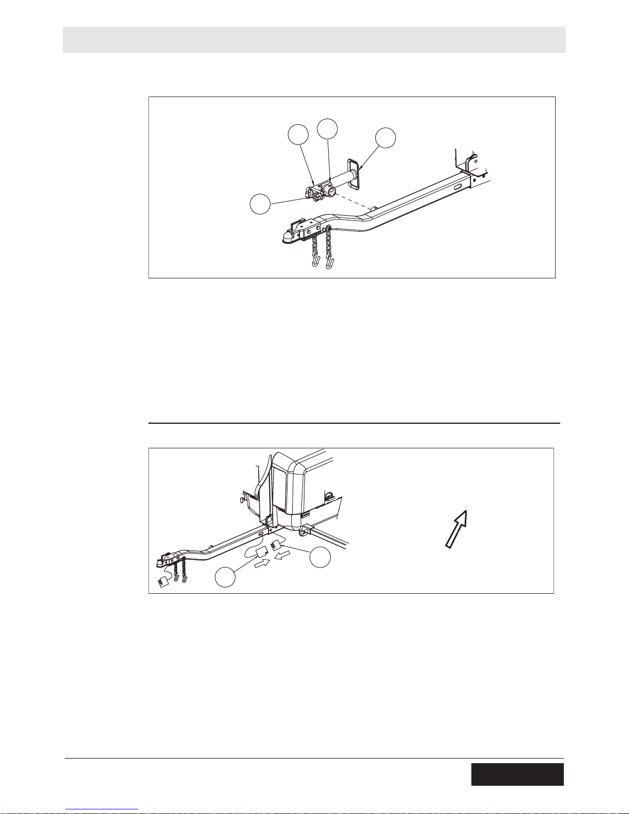
LTN Appendix V—Standard Racked Assembly
Installing the
tongue jack
Follow the procedure below to Install the tongue jack.
1. Locate the 2000 lb. 10-inch travel jack (“tongue jack”) (J).
J1
J
J2
J3
wc_gr006524
2. If necessary, remove the locking pin (J3) from the holes in the tongue jack.
3. Fit the socket (J1) over the circular boss on the tongue assembly.
4. Rotate the tongue jack so that the foot (J2) rests on the ground.
Connecting
the trailer
wiring
5. Align the top hole in the socket with the top hole on the circular boss.
6. Insert the locking pin into the holes. Push the locking pin through both sets of
holes (top and bottom) to fasten the tongue jack in place.
1. Locate connectors (K) and (L).
L
K
wc_gr006525
2. Plug the tongue wiring harness connector (K) into tongue wiring harness
connector (L).
3. Insert connector plug body into the hole on the skid bracket. (See arrow.)
wc_tx001216gb.fm 89
Page 90

Appendix V—Standard Racked Assembly LTN
13.7 Installing the Tower Lock Bracket
Procedure
Follow the procedure below to Install the tower lock bracket.
1. Locate the following in hardware bag 5:
(1) tower lock bracket (M)
(3) M8 x 20 hex head mounting screws (N)
(3) M8 flat washers (O)
(3) M8 lock nuts (P)
O
P
N
M
2. Install the tower lock bracket on the tower as shown.
3. Torque the mounting screws to 35 Nm (25 ft.lbs.).
wc_gr006526
90 wc_tx001216gb.fm
Page 91

LTN Appendix V—Standard Racked Assembly
0
13.8 Installing the Tower Cradle
Materials
needed
Procedure
Tower cradle
Hardware bag 4 (tower cradle hardware)
Follow the procedure below to assemble the tower cradle (Y).
Y7
Y8
Y9
Y
Y4
Y3
Y2
Y1
Y6
Y11
Y5
Y9
Y10
wc_gr00653
1. Using (4) M10 x 16 serrated flange screws (Y1), install the tower cradle to the
Light Tower upper frame. Torque the screws to 58 Nm (42.8 ft.lbs.)
2. Using (2) M6 x 20 serrated flange screws (Y4), install the radiator access cover
(Y2) and radiator cover plate (Y3) to the tower cradle. Torque the screws to 16
Nm (11.5 ft.lbs.).
3. Using (2) M12 washers (Y9) and the M12 locknut (Y10), install the tower lock
pin (Y8) on the tower cradle
Note: Do not tighten locknut Y10 until the next assembly topic (“Installing the
Tower”).
4. Place the tower damper (Y7) over the tower lock pin.
Note: The large hole on the tower damper must face down.
5. Install the hitch pin assembly (Y11) to the tower cradle using the M5 x 16 screw
(Y5) and the M5 locknut (Y6).
wc_tx001216gb.fm 91
Page 92

Appendix V—Standard Racked Assembly LTN
AA1
AA1
AA2
AA2
13.9 Installing the Tower
Materials
needed
Installing the
tower
Tower assembly
Hardware bag 8 (tower install assembly)
Follow the procedure below to install the tower.
AA1
AA2
AA1
AA2
Z3
Z4
Z2
Z1
Z
Y8
Y10
Reversing the
winch handles
wc_gr006531
1. Align the tower assembly (Z) on top of the Light Tower enclosure as shown.
2. Place the tower assembly over the tower lock pin (Y8) and secure it with the
hitch pin. This will help to keep the tower in alignment for the next step.
3. Insert the clevis pin (Z1) through the holes in the tower support (Z4) and the
tower.
4. Place the 1-inch flat washer (Z3) over the end of the clevis pin. Fasten the tower
in place with the 3/16-x-2 cotter pin (Z2).
5. Adjust the alignment of the tower lock pin (Y8) if necessary. Torque lock nut
(Y10) to 48 Nm (35 ft.lbs.).
The winch handles (AA2) are installed backward to protect them from shipping
damage. Reverse each handle orientation as follows:
1. Remove the nut (AA1) and remove the winch handle from the stem.
2. Turn the winch handle so that the handgrip is oriented as shown in the
illustration.
3. Re-install the winch handle and the nut.
92 wc_tx001216gb.fm
Page 93
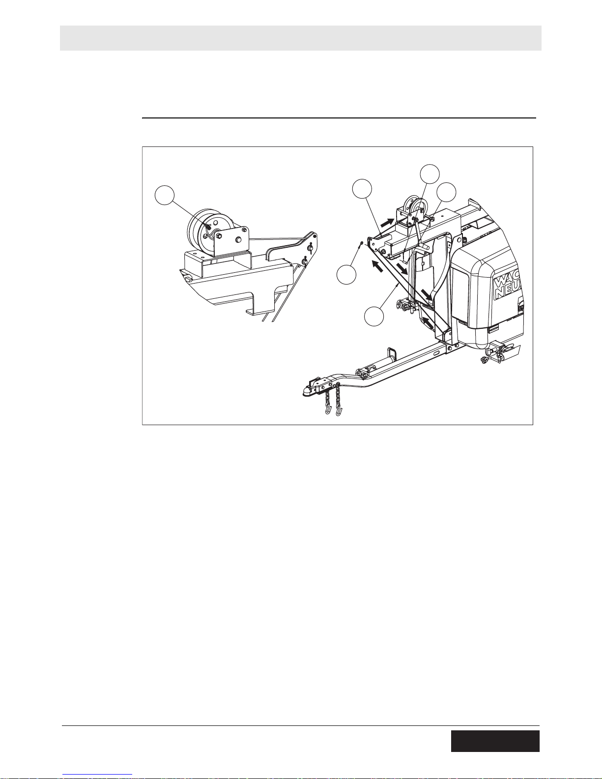
LTN Appendix V—Standard Racked Assembly
2
13.10 Installing the Tower Pivot Cable
Materials
needed
Installing the
tower
Tower pivot cable (AA8)
Hardware Bag 8 (Tower Install Assembly)
Follow the procedure below to install the tower pivot cable.
AA
AA9
AA7
AA8
AA6
AA5
wc_gr00653
1. One end of the tower pivot cable has a loop. Insert the retainer pin (AA5)
through the hole in the upper pulley mount (AA9) and pass it through the cable
loop.
2. Place the M12 washer (AA7) over the end of the retainer pin and secure it with
the cotter pin (AA6).
3. Route the free end of the cable around the lower pulley and over the top of the
upper pulley. Refer to the directional arrows in the illustration above.
4. Pass the cable below the winch drum and wind it two or three times around the
winch drum.
5. Pass the free end of the cable through the hole in the winch drum. Wind the
cable once around the bearing drum axle.
6. Loosen the two nuts on the cable retainer (AA) and insert the free end of the
cable through the retainer so that approximately 1 cm (3/8 in.) of cable extends
beyond the retainer. Torque the nuts to 3 Nm (20-30 in.lbs.).
7. Rotate the winch counter-clockwise to take up any slack in the cable.
wc_tx001216gb.fm 93
Page 94

Appendix V—Standard Racked Assembly LTN
13.11 Installing the Lights
Materials
needed
Procedure
Light fixtures (4)
Hardware bag 6 (tower lights hardware)
Follow the procedure below to install the lights.
BB2
BB3
CC
CC3
BB1
BB
BB
CC1
CC2
wc_gr006533
1. Install the lig ht mount tu be (BB) on the tower using (2) M16 x 90 screws (BB1),
(2) B17 flat washers (BB2), and (2) M16 lock nuts (BB3). Torque the screws to
83 Nm (60 ft.lbs.)
Install the four light fixtures (CC) on the light tube as follows:
1. Position each light fixture so that the lamp is facing downward. Make sure that
the “T” handle (CC3) faces outward.
2. Install each light fixture on the light mount tube using an M18 lock nut (CC1) and
a B19 flat washer (CC2).
94 wc_tx001216gb.fm
Page 95

LTN Appendix V—Standard Racked Assembly
4
5
13.12 Connecting the Wiring at the Junction Box
Special tools
and materials
needed
Procedure
Installing the
coil cord
Coil cord (GG)
Panduit® crimper CT-100
Panduit® crimper CT-1550
Hardware bag 6
Follow the procedure below to connect the wiring at the junction box.
DD
DD2
DD2
DD1
wc_gr00653
1. Remove the screws and the cover plate from the junction box (DD).
2. Use two wrenches to loosen the connector (DD1) at the bottom of the junction
box.
Installing the
fixture cords
3. Insert the end of the coil cord through the con nector so that approximately 1 cm
(3/8 in.) of coil cord jacket extends into the junction box. Retighten connector
DD1.
4. Use two wrenches to loosen the four connectors (DD2) on the sides of the
junction box.
5. Refer to the diagram below and insert the fixture cords through the appropriate
connectors. Approximately 1 cm (3/8 in.) of each fixture cord jacket should
extend into the junction box. Retighten connectors DD2.
FF
L1
L3
L2
L4
L1
L3
L2
L4
wc_gr00653
This procedure continues on the next page.
wc_tx001216gb.fm 95
Page 96

Appendix V—Standard Racked Assembly LTN
Connecting
the wires
6. Refer to the ta ble below and connect the light fixture wires to the coil cord wires.
Use the small connectors and Panduit wire crimper CT-100.
Position Light wire Coil cord wire
L1 Black Red
White Orange
Green —
L2 Black Black
White Brown
Green —
L3 Black Yellow
White White
Green —
L4 Black Blue
White Purple
Green —
7. Connect the green wires from the fixture cords and coil cord, along with the
green/yellow ground wire, using the large connector and Panduit wire crimper
CT-1500.
8. Install the ring terminal on the ground wire to the ground screw (FF) in the
junction box.
96 wc_tx001216gb.fm
Page 97

LTN Appendix V—Standard Racked Assembly
13.13 Routing the Coil Cord
Procedure
Follow the procedure below to route the coil cord.
CN
R
L
wc_gr006536
1. At the base of the tower, wrap the coil cord around the tower twice, creating
loops of about 25 cm (10 in.) in diameter.
2. Loosen the connector (CN). Pass the en d of the coil cord through the con nector
so that approximately 1 m (3 ft) of wires extend inside the Light Tower cabinet,
and re-tighten the connector (CN).
3. Insert the red, black, brown, and orange wires from the coil cord into one of the
supplied looms. Pass this loom through the ballast bracket on the right side of
the machine (R).
4. Insert the yellow, blue, white, purple, and green wires from the coil cord into the
second loom. Pass this loom through the ballast bracket on the left side of the
machine (L).
wc_tx001216gb.fm 97
Page 98

Appendix V—Standard Racked Assembly LTN
13.14 Wiring the Ballasts and Terminal Strips
Procedure
Follow the procedure below to wire the ballasts and terminal strips.
G
BC
wc_gr006537
1. Remove the two ballast covers (BC) from the left and right sides of the Light
Tower.
2. Connect the green wire from the coil cord to the hexagonal grounding screw
(G).
3. Locate the four capacitors as shown below.
1
2
3
4
wc_gr006570
4. Connect four wires from the coil cord to the capacitors as follows:
Capacitor Wire from coil cord
1Red
2Black
3 Yellow
4Blue
5. Connect the remaining wires to terminal strips “A” and “B” according to the
diagram and tables on the next page. Torque all screws to 2.25 Nm (20 in.lbs.).
6. When all wires are connected to terminal strip s “A” and “B,” re-inst all the ballast
covers. Torque the ballast cover mounting screws to 5.0 Nm (3.5 ft.lbs.).
98 wc_tx001216gb.fm
Page 99

LTN Appendix V—Standard Racked Assembly
A
B
C
D
E
F
G
H
I
J
K
L
A
B
C
D
E
F
G
H
I
J
K
L
A
B
C
D
E
F
G
H
I
J
K
L
A
“A” “B”
Terminal strip “A” (right side of machine)
Position Wire description
A–F Not used
G Black / yellow from ballasts #1 and #2
H Black (#7) from control box
I Yellows (2) from ballast #1
J Yellows (2) from ballast #2
K White (#9) from control box
L Brown and orange from coil cord
A
B
C
D
E
F
G
H
I
J
K
L
B
wc_gr006538
wc_tx001216gb.fm 99
Terminal strip “B” (left side of machine)
Position Wire description
A Black / yellow from ballasts #3 and #4
B Black (#6) from control box
C Yellows (2) from ballast #3
D Yellows (2) from ballast #4
E White (#8) from control box
F White and purple from coil cord
G–L Not used
Page 100

Appendix V—Standard Racked Assembly LTN
13.15 Conclusion
This completes the assembly procedure for your Light Tower. Refer to your
Operator’s Manual for instructions on setting up, operating, maintaining, and
storing the machine.
Notes:
100 wc_tx001216gb.fm
 Loading...