

Page 1

Operator’s Manual
5200009218
Direct-Fired Air Heater
HDR155
Type HDR155
Document 5200009218
Date 1115
Revision 03
Language EN
Page 2

Copyright notice
© Copyright 2015 by Wacker Neuson Production Americas LLC
All rights, including copying and distribution rights, are reserved.
This publication may be photocopied by the original purchaser of the
machine. Any other type of reproduction is prohibited without express
written permission from Wacker Neuson Production Americas LLC.
Any type of reproduction or distribution not authorized by Wacker
Neuson Production Americas LLC represents an infringement of valid
copyrights. Violators will be prosecuted.
Trademarks
Manufacturer
Original instructions
All trademarks referenced in this manual are the property of their
respective owners.
Wacker Neuson Production Americas LLC
N92W15000 Anthony Avenue
Menomonee Falls, WI 53051 U.S.A.
Tel: (262) 255-0500 · Fax: (262) 255-0550 · Tel: (800) 770-0957
www.wackerneuson.com
This Operator’s Manual presents the original instructions. The original
language of this Operator’s Manual is American English.
Page 3
HDR 155 Foreword
Foreword
This heater is designed and approved for use as a construction heater in
accordance with the following standards.
CSA B140.0-03 3rd Edition (R2008)
CSA B140.8-1967 (R2001)
UL 733 4th Edition (Rev. April 22, 2010)
CHECK WITH YOUR LOCAL FIRE SAFETY AUTHORITY IF YOU HAVE
QUESTIONS ABOUT APPLICATIONS.
Other standards govern the use of fuel gases and heat producing products in
specific applications. Your local authority can advise you about these standards.
THE INSTALLATION OF THE UNIT SHALL BE IN ACCORDANCE WITH THE
REGULATIONS OF THE AUTHORITIES HAVING JURISDICTION.
In addition, as a standard practice for installation, Wacker Neuson recommends
referencing the current issue of CSA B139, Installation Code for Oil Burning
Equipment in Canada and NFPA 31 Standard for the Installation of Oil-Burning
Equipment in the USA.
WARNING
Risk of personal injury or machine damage from improper use.
f Before using the machine, read and understand all instructions and follow them
carefully.
f The manufacturer is not responsible for damages to goods or persons due to
improper use of this machine.
WARNING
Failure to comply with the precautions and instructions provided with this machine
can result in death, serious injury, and property loss or damage from fire, explosion,
burns, asphyxiation, carbon monoxide poisoning, and/or electric shock.
f Before using the machine, read and understand all precautions and instructions
that have been provided. Follow them carefully.
f Only persons who can understand and follow the precautions and instructions
should use or service this machine.
f Contact the manufacturer if you need assistance with operating the machine or
need replacement manuals or labels.
wc_tx003204gb.fm 3
Page 4
Foreword HDR 155
WARNING
Work site fire, burn, inhalation, and explosion hazards.
f Keep solid combustibles, such as building materials, paper, or cardboard at a
safe distance away from the machine as recommended by the instructions.
f Never use this machine in spaces which do or may contain volatile or airborne
combustibles, or products such as gasoline, solvents, paint thinner, dust particles, or unknown chemicals.
WARNING
Not for use in homes or recreational vehicles. Installing this machine in a home or
RV may result in fire, explosion, property damage, personal injury, or death.
f Operate the machine only for applications specified in Machine Description and
Intended Use.
SAVE THESE INSTRUCTIONS—This manual contains important instructions for
the machine model below. These instructions have been written expressly by
Wacker Neuson Production Americas LLC and must be followed during installation,
operation, and maintenance of the machine.
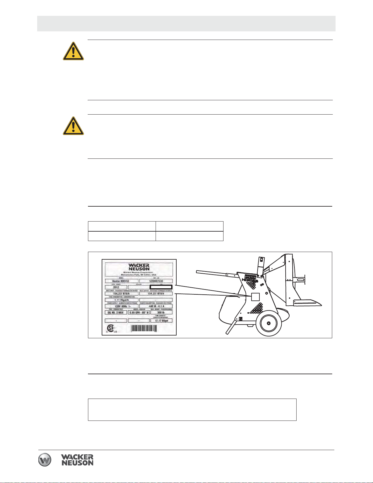
Machine
identification
Serial number
(S/N)
This manual covers the machine with the following item number:
Machine Item Number
HDR 155 5200007530
wc_gr010181
A nameplate listing the model number, item number, revision number, and serial
number is attached to this machine. The location of the nameplate is shown above.
For future reference, record the serial number in the space provided below. You will
need the serial number when requesting parts or service for this machine.
Machine
documentation
Serial Number:
From this point forward in this documentation, Wacker Neuson Production
Americas LLC will be referred to as Wacker Neuson.
4 wc_tx003204gb.fm
Page 5

HDR 155 Foreword
Keep a copy of the Operator’s Manual with the machine at all times.
Use the separate Parts Book supplied with the machine to order replacement
parts.
If you are missing any of these documents, please contact Wacker Neuson to
order a replacement or visit www.wackerneuson.com.
When ordering parts or requesting service information, be prepared to provide
the machine model number, item number, revision number, and serial number.
Expectations
for
information in
this manual
Manufacturer’s
approval
This manual provides information and procedures to safely operate and main-
tain the above Wacker Neuson model(s). For your own safety and to reduce the
risk of injury, carefully read, understand, and observe all instructions described
in this manual.
Wacker Neuson expressly reserves the right to make technical modifications,
even without notice, which improve the performance or safety standards of its
machines.
The information contained in this manual is based on machines manufactured
up until the time of publication. Wacker Neuson reserves the right to change
any portion of this information without notice.
This manual contains references to approved parts, attachments, and
modifications. The following definitions apply:
Approved parts or attachments are those either manufactured or provided by
Wacker Neuson.
Approved modifications are those performed by an authorized Wacker Neu-
son service center according to written instructions published by Wacker Neuson.
Unapproved parts, attachments, and modifications are those that do not
meet the approved criteria.
Unapproved parts, attachments, or modifications may have the following
consequences:
Serious injury hazards to the operator and persons in the work area
Permanent damage to the machine which will not be covered under warranty
Contact your Wacker Neuson dealer immediately if you have questions about
approved or unapproved parts, attachments, or modifications.
wc_tx003204gb.fm 5
Page 6

Foreword HDR 155
6 wc_tx003204gb.fm
Page 7

HDR 155
Table of Contents
Foreword 3
1 Safety Information 9
1.1 Signal Words Used in this Manual ....................................................... 9
1.2 Machine Description and Intended Use ............................................. 10
1.3 Safety Guidelines for Operating the Machine ..................................... 11
1.4 Safety Guidelines for Operating Combustion Burners ....................... 14
1.5 Service Safety .................................................................................... 15
1.6 Safety Guidelines for Lifting and Transporting the Machine ............... 16
2 Labels 17
2.1 Label Locations .................................................................................. 17
2.2 Label Meanings .................................................................................. 18
3 Lifting and Transporting 22
4 Operation 23
4.1 Preparing the Machine for First Use ................................................... 23
4.2 Parts Included .................................................................................... 24
4.3 Assembling the Machine .................................................................... 25
4.4 Control / Component Locations .......................................................... 26
4.5 Adjusting the Heater Output Angle ..................................................... 27
4.6 Positioning the Machine ..................................................................... 28
4.7 Electrical and Grounding .................................................................... 30
4.8 Recommended Fuels and Fuel Blending Guide ................................. 31
4.9 Preliminary Checks ............................................................................ 31
4.10 Starting the Machine in Extremely Cold Weather ............................... 32
4.11 Starting the Machine .......................................................................... 33
4.12 Stopping ............................................................................................. 34
4.13 Operating Status Indicators ................................................................ 34
4.14 Installing and Using the Remote Thermostat ..................................... 35
5 Burner Setup 36
5.1 Removing and Installing the Burner Assembly ................................... 36
5.2 Setting Up the Burner ......................................................................... 37
5.3 Checking and Adjusting the Electrodes .............................................. 37
5.4 Replacing the Burner Nozzle .............................................................. 38
wc_bo5200009218_03TOC.fm
7
Page 8

Table of Contents
5.5 Adjusting the Air Damper ....................................................................39
5.6 Checking and Adjusting the Fuel Pressure .........................................40
HDR 155
6 Maintenance 42
6.1 Periodic Maintenance Schedule ..........................................................42
6.2 Inspecting and Cleaning the Machine .................................................43
6.3 Removing the Access Panel ...............................................................45
6.4 Replacing the Fuel Heater Filter ..........................................................46
6.5 Inspecting and Cleaning the Cadmium (CAD) Cell .............................47
6.6 Inspecting the Flame Head .................................................................48
6.7 Inspecting the Electrical Connections .................................................48
6.8 Long Term Storage .............................................................................49
7 Basic Troubleshooting 50
8 Technical Data 52
8.1 Machine ...............................................................................................52
8.2 Dimensions ..........................................................................................52
9 Schematics 53
9.1 HDR 155 ..............................................................................................53
8
wc_bo5200009218_03TOC.fm
Page 9

HDR 155 Safety Information
1 Safety Information
1.1 Signal Words Used in this Manual
This manual contains DANGER, WARNING, CAUTION, NOTICE, and NOTE
signal words which must be followed to reduce the possibility of personal injury,
damage to the equipment, or improper service.
This is the safety alert symbol. It is used to alert you to potential personal hazards.
f Obey all safety messages that follow this symbol.
DANGER
DANGER indicates a hazardous situation which, if not avoided, will result in death
or serious injury.
f To avoid death or serious injury from this type of hazard, obey all safety
messages that follow this signal word.
WARNING
WARNING indicates a hazardous situation which, if not avoided, could result in
death or serious injury.
f To avoid possible death or serious injury from this type of hazard, obey all safety
messages that follow this signal word.
CAUTION
CAUTION indicates a hazardous situation which, if not avoided, could result in
minor or moderate injury.
f To avoid possible minor or moderate injury from this type of hazard, obey all
safety messages that follow this signal word.
NOTICE: Used without the safety alert symbol, NOTICE indicates a situation
which, if not avoided, could result in property damage.
Note: A Note contains additional information important to a procedure.
wc_si000732gb.fm
9
Page 10

Safety Information HDR 155
1.2 Machine Description and Intended Use
Machine
description
Intended use
The HDR Heater is a direct-fired radiant heater. The machine operates on diesel
fuel. The machine consists of the following components:
Stainless steel combustion chamber
Blower
Single-stage burner
High-temperature shut-down device
Fuel tank
Safety tip switch
Fuel is consumed in a closed combustion chamber. Outside air is pulled into the
machine where it is heated. This clean, dry air is blown between the walls of the
combustion chamber to cool the machine. Access to the blower assembly is
protected by a guard fitted on the air inlet.
The HDR Heater is intended to provide heat on outdoor construction sites and in
other rugged applications. Do not use this machine indoors.
This machine has been designed and built strictly for the intended use described
above. Using the machine for any other purpose could permanently damage the
machine or seriously injure the operator or other persons on the work site. Machine
damage caused by misuse is not covered under warranty.
Optional
accessories
This machine has been designed and built in accordance with the latest global
safety standards. It has been carefully engineered to eliminate hazards as far as
practicable and to increase operator safety through protective guards and labeling.
However, some risks may remain even after protective measures have been taken.
They are called residual risks. On this machine, they may include exposure to:
exhaust emissions
hot surfaces such as exhaust vents and fuel heater
fuel and fuel fumes when refueling
high voltages and arc flash
To protect yourself and others, make sure you thoroughly read and understand the
safety information presented in this manual before operating the machine.
Wacker Neuson offers optional accessories for the machine. These accessories
include the following:
Remote thermostat
Contact your Wacker Neuson dealer for more information.
10
wc_si000732gb.fm
Page 11
HDR 155 Safety Information
1.3 Safety Guidelines for Operating the Machine
DANGER
Carbon monoxide. Using the machine indoors CAN KILL YOU IN MINUTES.
Exhaust gas contains carbon monoxide (CO). This is a deadly poison you cannot
see or smell. If you can smell the exhaust, you are breathing CO. Even if you
cannot smell the exhaust, you could be breathing CO.
f NEVER operate the machine inside an enclosed area, such as a home, tunnel,
or garage.
f ONLY use the machine outside and far away from windows, doors, and vents.
These openings can pull in exhaust.
f ALWAYS use a battery-powered or battery-backup CO alarm in nearby struc-
tures. Even when you use the machine correctly, CO may leak into nearby
structures.
f If you start to feel sick, dizzy, or weak after the machine has been running, move
to fresh air IMMEDIATELY. See a doctor. You could have carbon monoxide
poison.
Operator
training
Operator
qualifications
Before operating the machine:
Read and understand the operating instructions contained in all manuals
delivered with the machine.
Familiarize yourself with the location and proper use of all controls and safety
devices.
Contact Wacker Neuson for additional training if necessary.
When operating this machine:
Do not allow improperly trained people to operate the machine. People
operating the machine must be familiar with the potential risks and hazards
associated with it.
Only trained personnel are permitted to start, operate, and shut down the machine.
They also must meet the following qualifications:
have received instruction on how to properly use the machine
are familiar with required safety devices
The machine must not be accessed or operated by:
children
people impaired by alcohol or drugs
Application
area
wc_si000732gb.fm
Be aware of the application area.
Keep unauthorized personnel, children, and pets away from the machine.
Remain aware of changing positions and the movement of other equipment and
personnel in the application area/job site.
Be aware of the application area.
Do not operate the machine in areas that contain flammable objects, fuels, or
products that produce flammable vapors.
11
Page 12

Safety Information HDR 155
Safety
devices,
controls, and
attachments
Safe
operating
practices
Only operate the machine when:
All safety devices and guards are in place and in working order.
All controls operate correctly.
The machine is set up correctly according to the instructions in the Operator’s
Manual.
The machine is clean.
The machine’s labels are legible.
To ensure safe operation of the machine:
Do not operate the machine if any safety devices or guards are missing or
inoperative.
Do not modify or defeat the safety devices.
Only use accessories or attachments that are approved by Wacker Neuson.
When operating this machine:
Remain aware of the machine’s moving parts. Keep hands, feet, and loose
clothing away from the machine’s moving parts.
When operating this machine:
Do not operate a machine in need of repair.
Personal
Protective
Equipment
(PPE)
Machine
condition
Wear the following Personal Protective Equipment (PPE) while operating this
machine:
Close-fitting work clothes that do not hinder movement
Safety glasses with side shields
Hearing protection
Safety-toed footwear
Only operate the machine when:
The combustion chamber is in proper working order.
All safety devices and guards are in place and in working order.
All controls operate correctly.
The machine is set up correctly according to the instructions in the Operator’s
Manual.
The machine is clean.
The machine’s labels are legible.
When operating the machine:
Do not modify or defeat the safety devices.
Do not use worn electrical cords.
Do not use faulty fuel supplies.
Work space
Follow the guidelines below when placing the machine in the workspace.
Position the machine on a firm, noncombustible, level surface.
wc_si000732gb.fm
12
Page 13

HDR 155 Safety Information
Keep the area immediately surrounding and underneath the machine clean,
neat, and free of debris and combustible materials.
Keep the area above the machine clear of debris that could fall on the machine.
Do not position electrical cords under the machine or over the top of the
machine.
WARNING
Fire hazard. Do not move the machine while it is plugged in, even if power is lost.
f Turn off the machine, wait 10 minutes, disconnect power cord, and let it cool
completely.
While
operating the
machine
After use
Inspect the machine before startup, and monitor it regularly during operation.
Do not exceed the maximum heat output of the machine.
Disconnnect power from the machine.
Store the machine properly when it is not being used.
wc_si000732gb.fm
13
Page 14

Safety Information HDR 155
1.4 Safety Guidelines for Operating Combustion Burners
When using the machine:
Clean up any spilled fuel immediately.
Replace the fuel tank cap after refueling the machine.
Refill the fuel tank in a well-ventilated area.
Shut down the generator, if equipped, when refueling.
When using the machine:
DANGER
Carbon monoxide. Using this machine indoors CAN KILL YOU IN MINUTES.
Exhaust gas contains carbon monoxide (CO). This is a deadly poison you cannot
see or smell. If you can smell the exhaust, you are breathing CO. Even if you
cannot smell the exhaust, you could be breathing CO.
f NEVER operate the machine inside an enclosed area, such as a home, tunnel,
or garage.
f ONLY use the machine outside and far away from windows, doors, and vents.
These openings can pull in exhaust gas.
f ALWAYS use a battery-powered or battery-backup CO alarm in nearby struc-
tures. Even when you use the machine correctly, CO may leak into nearby
structures.
f If you start to feel sick, dizzy, or weak after the machine has been running, move
to fresh air IMMEDIATELY. See a doctor. You could have carbon monoxide
poisoning.
When refueling the machine:
Do not fill or drain the fuel tank near an open flame or while the machine is
running.
Do not smoke when refueling the machine.
Do not use gasoline, crankcase oil, or any oil containing gasoline.
14
wc_si000732gb.fm
Page 15

HDR 155 Safety Information
1.5 Service Safety
Service
training
Precautions
Before servicing or maintaining the machine:
Read and understand the instructions contained in all manuals delivered with
the machine.
Familiarize yourself with the location and proper use of all controls and safety
devices.
Only trained personnel shall troubleshoot or repair problems occurring with the
machine.
Contact Wacker Neuson for additional training if necessary.
When servicing or maintaining this machine:
Do not allow improperly trained people to service or maintain the machine.
Personnel servicing or maintaining the machine must be familiar with the
associated potential risks and hazards.
Follow the precautions below when servicing or maintaining the machine.
Read and understand the service procedures before performing any service to
the machine.
All adjustments and repairs must be completed before operation. Do not
operate the machine with a known problem or deficiency.
All repairs and adjustments shall be completed by a qualified technician.
Turn off the machine before performing maintenance or making repairs.
Machine
modifications
Replacing
parts and
labels
Cleaning
When servicing or maintaining the machine:
Use only accessories/attachments that are approved by Wacker Neuson.
When servicing or maintaining the machine:
Do not defeat safety devices.
Do not modify the machine without the express written approval of Wacker
Neuson.
Replace worn or damaged components.
Replace all missing and hard-to-read labels.
When replacing electrical components, use components that are identical in
rating and performance to the original components.
When replacement parts are required for this machine, use only Wacker
Neuson replacement parts or those parts equivalent to the original in all types of
specifications, such as physical dimensions, type, strength, and material.
When cleaning and servicing the machine:
Keep the machine clean and free of debris such as leaves, paper, cartons, etc.
Keep the labels legible.
When cleaning the machine:
Do not clean the machine while it is running.
wc_si000732gb.fm
15
Page 16

Safety Information HDR 155
Never use gasoline or other types of fuels or flammable solvents to clean the
machine. Fumes from fuels and solvents can become explosive.
Personal
Protective
Equipment
(PPE)
Wear the following Personal Protective Equipment (PPE) while servicing or
maintaining this machine:
Close-fitting work clothes that do not hinder movement
Safety glasses with side shields
Hearing protection
Safety-toed footwear
In addition, before servicing or maintaining the machine:
Tie back long hair.
Remove all jewelry (including rings).
After Use
Stop the engine when the machine is not being operated.
Close the fuel valve on engines equipped with one when machine is not being
operated.
Ensure that the machine will not tip over, roll, slide, or fall when not being
operated.
Store the machine properly when it is not being used. The machine should be
stored in a clean, dry location out of the reach of children.
1.6 Safety Guidelines for Lifting and Transporting the Machine
When lifting the machine:
Make sure slings, chains, hooks, ramps, jacks, forklifts, cranes, hoists, and any
other type of lifting device used is attached securely and has enough weight-
bearing capacity to lift or hold the machine safely. See section Technical Data
for machine weight.
Remain aware of the location of other people when lifting the machine.
Only use the lifting points and tie-downs described in the Operator’s Manual.
Make sure the transporting vehicle has sufficient load capacity and platform size
to safely transport the machine.
To reduce the possibility of injury:
Do not stand under the machine while it is being lifted or moved.
Do not get onto the machine while it is being lifted or moved.
16
wc_si000732gb.fm
Page 17
HDR 155 Labels
2 Labels
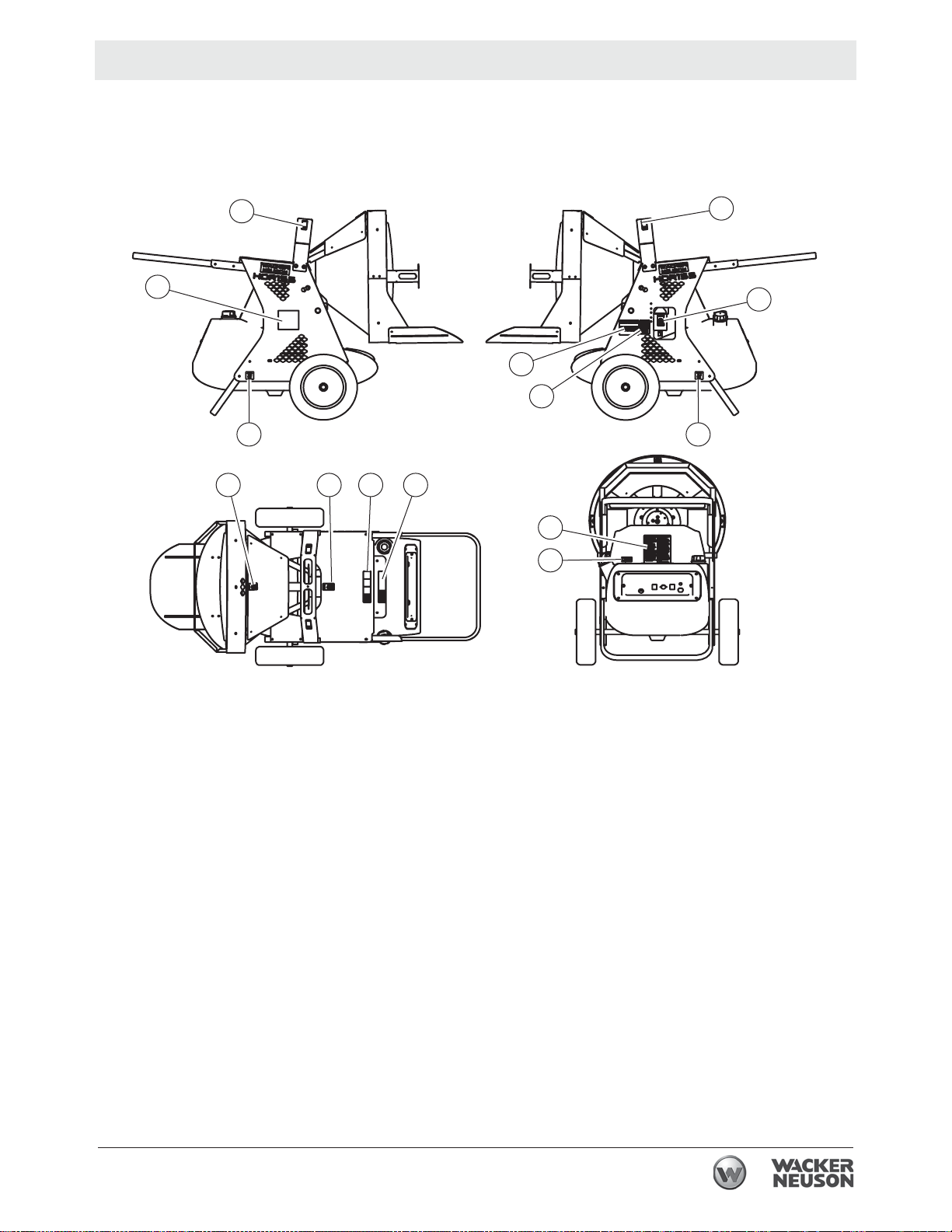
2.1 Label Locations
M
I
D
E
L
G HFF
J
K
I
F
L
wc_gr010203
wc_si000733gb.fm
17
Page 18
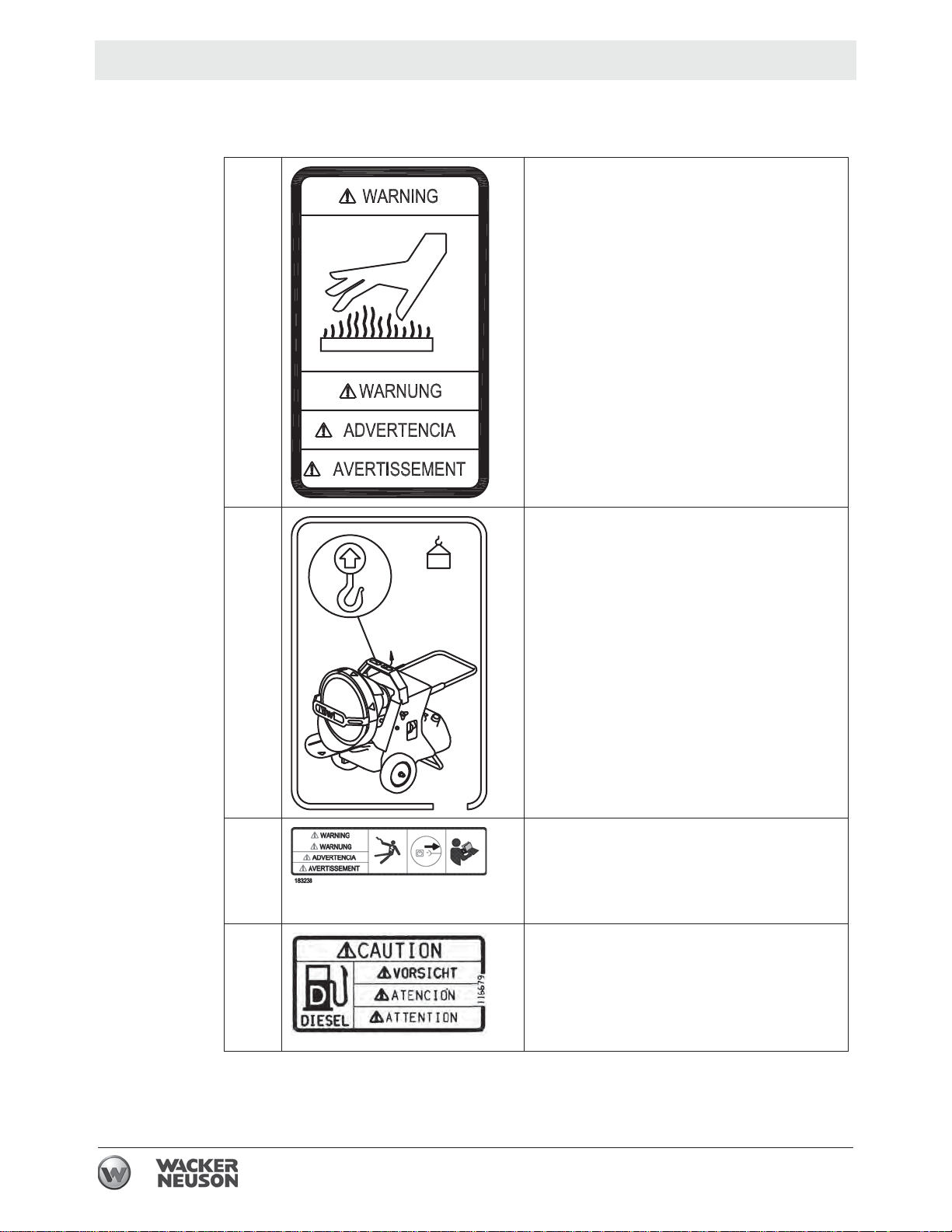
Labels HDR 155
5200012779
2.2 Label Meanings
AWARNING
Hot surface
CNOTICE
Lifting point
136 kg
(300 LB)
DWARNING!
Electric shock hazard.
Disconnect power before servicing.
Read Operator’s Manual.
ECAUTION
This machine uses diesel fuel.
18
wc_si000733gb.fm
Page 19

HDR 155 Labels
113726
F Tie-down point.
113726
GDANGER
Asphyxiation hazard.
Using this machine indoors CAN KILL YOU
IN MINUTES. Burner exhaust and generator
exhaust (if the machine is equipped with a
generator) contains carbon monoxide. This is
a poison you cannot see or smell.
Never use inside an enclosed area even if
doors and windows are open.
Only use outside away from windows, doors,
and vents.
Read the Operator’s Manual before use.
HCAUTION
Hot while in operation. Do not touch. Keep
children, clothing, and combustibles away.
wc_si000733gb.fm
19
Page 20

Labels HDR 155
JWARNING
Read and understand the supplied Opera-
tor's Manual before operating this
machine.
The requirements of local authorities hav-
ing jurisdiction shall be followed.
Do not use heater in close proximity of
combustible surfaces or materials.
Ensure fresh air supply to space where
heater is used.
Equipment must be grounded.
Use only light diesel oil No. 2 or kerosene.
Do not use gasoline or crankcase drain-
ing.
Do not fill the tank while the unit is operat-
ing.
Never pull electrical socket while heater is
running.
Do not start the heater when the combus-
tion chamber is hot.
Do not start the heater when excess oil
has accumulated in the chamber.
Allow unit to cool before shutdown. Stop
heater only at control panel switch in order
to ensure automatic cooling off. Heater will
stop by itself after automatic cooling off.
Clean fuel filter regularly and drain water
from fuel tank if necessary.
When heater is first used after a long stor-
age period it might be necessary to reset
the machine once or several times by the
reset button. The button will light up; wait
two minutes before resetting.
Do not tamper with the unit. Have a com-
petent serviceman make any adjustments.
Unplug machine before removing the
cover for any maintenance.
OCAUTION
Floor guard must be fully extended before
operating heater.
Minimum clearances from combustible material must be:
30" from side and rear (air inlet) of heater.
80" from surfaces above heater.
40" from air outlet of heater
20
wc_si000733gb.fm
Page 21

HDR 155 Labels
5200012778
˚
PCAUTION
CAUTION
ATTENTION
Burn hazard. The front of the machine gets
very hot during operation. Do not touch the
1010˚
front of the machine when adjusting.
wc_si000733gb.fm
21
Page 22

Lifting and Transporting HDR 155
3 Lifting and Transporting
Requirements
Transport vehicle capable of carrying 180 lbs (81.6 kg)
Crane or lift capable of carrying 180 lbs (81.6 kg)
NOTICES Do not tow this machine.
Do not route tie-down straps or chains over the top of the machine.
Fuel may leak from the fuel tank cap during transport. Clean up any leaked fuel
before using the machine.
WARNING
Crushing hazard.
f Only qualified riggers should attempt aerial lifting of this machine.
Guidelines
Follow the guidelines below when lifting and transporting this machine.
Turn off the machine, disconnect the power cord, and let it cool completely.
Cover all openings on the machine to avoid infiltration from road debris and dust.
When using an aerial lifting rig, use the designated lifting point (b) on top of the
machine.
Use the manual transport handle when relocating the machine within the job site.
When tying down the machine, route tie-down straps or chains through the
lower frame only.
Use only the designated tie-down locations (a).
Note: There is one tie-down located behind each wheel.
b
a
wc_gr010034
22
wc_tx003205gb.fm
Page 23

HDR 155 Operation
4 Operation
DANGER
Carbon monoxide. Using the machine indoors CAN KILL YOU IN MINUTES.
Exhaust gas contains carbon monoxide (CO). This is a deadly poison you cannot
see or smell. If you can smell the exhaust, you are breathing CO. Even if you
cannot smell the exhaust, you could be breathing CO.
f NEVER operate the machine inside an enclosed area, such as a home, tunnel,
or garage.
f ONLY use the machine outside and far away from windows, doors, and vents.
These openings can pull in exhaust.
f ALWAYS use a battery-powered or battery-backup CO alarm in nearby struc-
tures. Even when you use the machine correctly, CO may leak into nearby
structures.
f If you start to feel sick, dizzy, or weak after the machine has been running, move
to fresh air IMMEDIATELY. See a doctor. You could have carbon monoxide
poison.
4.1 Preparing the Machine for First Use
1. Make sure all loose packaging materials have been removed from the machine.
2. Check the machine and its components for damage. If there is visible damage,
do not operate the machine! Contact your Wacker Neuson dealer immediately
for assistance.
3. Take inventory of all items included with the machine and verify that all loose
components and fasteners are accounted for.
4. Attach component parts not already attached.
5. Add fluids as needed and applicable, including fuel, engine oil, and battery acid.
6. Move the machine to its operating location.
wc_tx003206gb.fm
23
Page 24

Operation HDR 155
4
4.2 Parts Included
Q
X
W
R
S
U
T
V
ABCDEFGHI LMNO
Ref. Qty. Description Ref. Qty. Description
A*
B*
C*
D* 4
E* 4
F* 4
G* 4
H* 2
I* 4
L* 4
M* 4
4Bolt
8 Washer
4 Lock nut
Allen-head screw
Lock washer
Washer
Screw
Locking pin
Washer
Hexagonal bolt
Wing nut
N* 4
O* 4
P1
Q
R
S
T
U
V
W
X
Washer
Bolt with washer
Assembly diagram
1 Front guard
1 Lift bar
1Handle
2 Wheel
1Foot suport
1Axle
1 Floor guard
1 Bottom guard
P
wc_gr01057
*Included in hardware bag.
24
wc_tx003206gb.fm
Page 25

HDR 155 Operation
4.3 Assembling the Machine
Requirements
Procedure
Standard tools
Extra person or a lifting device capable of supporting the weight of the machine
Perform the procedure below to assemble the machine.
1. Install the handle (S) using the bolts (A), washers (B), and lock nuts (C).
2. Install the lift bar (R) using the allen-head screws (D), lock washers (E), and
washers (F).
3. Install the front guard
4. Install the floor guard (W) using the wing nuts (M) and washers (N).
5. Install the foot support (U) using the screws (G).
6. Slide the axle (V) through the holes on both sides of the machine and secure it
using the hexagonal bolts (L).
7. Install washers (I) on both ends of the axle then slide the wheels (T) onto the
shaft. Secure the wheels using the remaining washers (I) and locking pins (H).
(Q)
and bottom guard
R
(X)
using the bolts with washers
S
C
B
(O)
.
B
A
O
Q
F
E
D
X
G
W
T
N
N
U
V I
MM
L
ABCDEFGHI LMNO
I
H
wc_tx003206gb.fm
wc_gr010572
25
Page 26
Operation HDR 155
4.4 Control / Component Locations
a b c d
e
f
r q p o
ON
RESET
ON
m
l k
j i
h
n
wc_gr009909
Ref Description Ref Description
a Combustion chamber j Drain plug
b Upper guard k Fuel pump
c Lifting device l Fuel filter
d Burner (flame head) m Lower (floor) guard
e Transport handle n Power cord
f Fuel tank cap o Power indicator
g Fuel tank p Thermostat receptacle
h Support q Operation mode switch
i Fan r Burner fault lamp and reset button
g
26
wc_tx003206gb.fm
Page 27
HDR 155 Operation
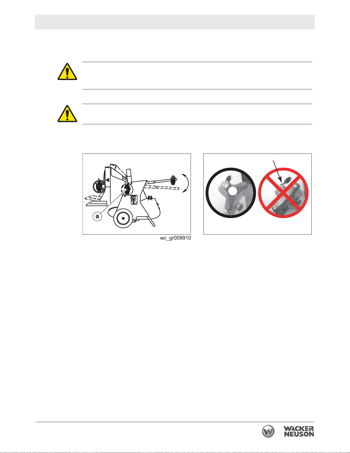
4.5 Adjusting the Heater Output Angle
Requirement
Procedure
Heater on a level surface.
CAUTION Pinch hazard. Several areas of the machine present pinching hazards if
not properly alligned and secured.
f Be sure to align and secure the machine properly when adjusting.
CAUTION Burn hazard. The front of the machine gets very hot during operation.
f Do not touch the front of the machine while adjusting.
Follow the procedure below to adjust the heater ouput angle.
1. Loosen the locking handles (a).
o
10
a
wc_gr010069
2. Tilt the heater up or down (maximum 10°) until the desired angle is achieved.
3. Tighten the locking handles (a) only when allignment is correct.
wc_tx003206gb.fm
27
Page 28

Operation HDR 155
4.6 Positioning the Machine
DANGER
Carbon monoxide. Using the machine indoors CAN KILL YOU IN MINUTES.
Exhaust gas contains carbon monoxide (CO). This is a deadly poison you cannot
see or smell. If you can smell the exhaust, you are breathing CO. Even if you
cannot smell the exhaust, you could be breathing CO.
f NEVER operate the machine inside an enclosed area, such as a home, tunnel,
or garage.
f ONLY use the machine outside and far away from windows, doors, and vents.
These openings can pull in exhaust.
f ALWAYS use a battery-powered or battery-backup CO alarm in nearby struc-
tures. Even when you use the machine correctly, CO may leak into nearby
structures.
f If you start to feel sick, dizzy, or weak after the machine has been running, move
to fresh air IMMEDIATELY. See a doctor. You could have carbon monoxide
poison.
CO Alarms
WARNING
Fire hazard. Do not move the machine while it is plugged in, even if power is lost.
f Turn off the machine, wait 10 minutes, disconnect the power cord, and let it cool
completely.
WARNING
Fire hazard. Machines positioned on a hill or an incline may slide, break away or
roll over.
f Do not position the machine on a hill or an incline.
WARNING
Explosion and fire hazard. Risk of severe injury or death.
f Do not operate the machine near flammable vapors, fuels, or combustibles.
Because this machine produces carbon monoxide (CO), Wacker Neuson
recommends that CO alarms be installed in all structures in close proximity to the
machine. CO alarms provide an extra measure of protection against this poison
that you cannot see or smell.
Install battery-operated CO alarms or plug-in CO alarms with battery backup,
according to the manufacturer’s instructions. CO alarms should be certified to the
requirements of the latest safety standards (UL 2034, IAS 6-96, or CSA 6.19.01).
Test the CO alarm batteries monthly.
This procedure continues on the next page.
wc_tx003206gb.fm
28
Page 29

HDR 155 Operation
Continued from the previous page.
Requirements
Guidelines
Tip-over
protection
Position the machine:
So that burner exhaust will not enter nearby structures.
So that the machine does not block traffic.
So that the machine is not close to any combustibles or flammable vapor.
So that the machine is not exposed to high levels of dust or airborne debris.
So that all of the machine’s access doors/panels may be accessed.
So that the cord does not pose a tripping hazard, and so the cord cannot be
damaged by machines or other equipment on the job site.
So that the machine is not sitting in pooled water or deep snow.
Machine must be on flat, firm surface.
Observe the following guidelines when positioning the machine for operation.
Installer must be familiar with all applicable laws, codes, regulations, or other
restrictions regarding installation of direct-fired radiant heaters.
Install wedge blocks under the wheels to prevent movement.
Installation must adhere to proximity restrictions.
This machine features tip-over protection. Operation is disabled if the machine tips
past thirty five degrees from the horizontal. Return the machine to a horizontal
position to resume operation.
Proximity
restrictions
The machine must be located a safe distance from any other structures, vehicles,
materials or other combustible surfaces. The following proximity restrictions apply
for all machine installations.
30" (0.76 m) from side and rear (air inlet) of heater
80" (2.03 m) from surfaces above heater
40" (1.02 m) from air outlet of heater
20' (6 m) from outlet to external fuel container
wc_tx003206gb.fm
29
Page 30
Operation HDR 155
4.7 Electrical and Grounding
WARNING
Fire and electric shock hazards. The use of an innappropriate power supply, or
undersized extension cords, can lead to fire and electric shock. Fire and electric
shock can cause severe injury.
f Before use, ensure that the machine is properly connected to an appropriate
power source and grounded per the requirements provided below.
f Do not use undersized extension cords.
Electrical
requirements
Grounding
requirements
Ensure that the machine is connected to a reliable, consistent source of electric
power.
The electric power source must be grounded per the requirements below and
connected to a freely accessible circuit breaker.
Ensure that extension cords (if used) are properly sized for the installation. Do
not use worn, bare, or frayed cords!
Restrictions for extension cords:
Use only 3-wire type extension cords with heavy-duty plugs.
The maximum length of extension cord usage per circuit is 30 m (100 ft).
Use 12-gauge extension cords for lengths up to 15 m (50 ft).
Use 10-gauge extension cords for lengths up to 30 m (100 ft).
Electrical grounding must comply with the National Electric Code ANSI/NFPA 70
or the CSA C22.1 Canadian Electrical Code, Part 1.
CAUTION
Burn hazard. The self-regulating fuel heater, located inside the fuel filter canister,
will initiate when power is connected to the machine. The surface of the fuel filter
canister may become very hot.
f Use caution when working with the fuel filter canister.
Connecting
power
Perform the procedure below to connect power to the machine.
1. Verify that the operation mode switch is in the OFF (0) position.
2. Connect the main power cord cord to a properly-rated power source.
Note: If the ambient temperature is below freezing, wait 10–30 minutes before
proceeding.
wc_tx003206gb.fm
30
Page 31
HDR 155 Operation
4.8 Recommended Fuels and Fuel Blending Guide
Low ambient temperatures cause diesel fuels to gel. Gelled fuels will cause burner
ignition failure and/or burner fuel pump damage. Always use the proper fuel for the
conditions.
Fuel Blend Guide
Lowest expected ambient
temperature °F (°C)
Below 5 (-15) 50-50 blend of #2 diesel
Generator-powered Shore-powered
100% #1 diesel plus
and #1 diesel, plus
additives
OR
50-50 blend #2 diesel and
K1 kerosene, plus
additives
additives
OR
100% K1 kerosene,
plus additives
5 to 25 (-15 to -4) 70-30 blend of #2 diesel and #1 diesel, plus additives
Above 25 (-4) Winter-blend diesel
NOTICE: Do not use B20 or any other type of biodiesel fuel in this machine.
CAUTION
Fire hazard.
f Do not use gasoline, crankcase oil, or any oil containing gasoline.
4.9 Preliminary Checks
Checks
Before starting the machine, check the following items.
Fuel tank full
Fuel tank cap secure
Operation mode switch in the OFF position
Power supply connected
Remote thermostat (if applicable) installed
Lower (floor) guard fully extended
Reset button illuminated green
Note: If the button is illuminated red, it must be pressed to reset the machine.
OR
70-30 blend of #2 diesel and K1 kerosene,
plus additives
wc_tx003206gb.fm
31
Page 32

Operation HDR 155
4.10 Starting the Machine in Extremely Cold Weather
Cold weather
Preheating
the fuel
Troubleshooting
In temperatures below 32°F (0°C), it may be necessary to preheat the fuel inside
the fuel filter canister. The fuel filter canister is equipped with a low-wattage heating
element specially designed for this purpose. See below for instructions.
.
WARNING
Burn hazard. The external surface of the machine and fuel filter may be hot.
f Wear safety gloves when handling the machine components.
Note: Excess heating may increase the need for maintenance. See topics
“Replacing the Fuel Filter” and “Replacing the Burner Nozzle”.
To preheat the fuel, carry out the following procedure.
1. Connect power to the machine. See topic Connecting Power to the Machine
(Preheating).
2. Wait 20–30 minutes—longer for colder temperatures.
3. Start the machine. See topic Starting the Machine.
Note: In extreme wind, the machine may need to be temporarily blocked from the
wind in order to start.
1. If the burner does not start on the first attempt, allow the power-on sequence to
cycle again.
2. If, after the second power-on sequence completes, the machine will not fire,
move the power switch to the OFF position.
3. Wait another 20–30 minutes and attempt to start the machine again.
32
wc_tx003206gb.fm
Page 33

HDR 155 Operation
4.11 Starting the Machine
Requirements
Procedure
Machine properly positioned
Power connected
Pre-starting checks completed
WARNING
Burn hazard. The external surface of the machine and fuel filter may be hot.
f Wear safety gloves when handling the machine components.
To start the machine, follow the procedure below.
1. Select an operation mode.
a. Continuous heat mode (I)
b. thermostat mode (II)
ON
ON
ON
RESET
ON
Operational
sequence
ON
ON
wc_gr010009
The following sequence of events will occur.
1. The burner blower will start.
2. The burner will start firing.
In applications in which the remote thermostat is not being used (I), the
burner will fire continuously.
In applications in which the remote thermostat is being used (II), the burner
will fire until the air temperature of the application area reaches the target
temperature set by the remote thermostat. At that time, the burner will shut
off. When the air temperature of the application area falls below the target
temperature set by the remote thermostat, the burner will refire. The process
continues as long as there is fuel for the burner.
wc_tx003206gb.fm
33
Page 34

Operation HDR 155
4.12 Stopping
Procedure
Follow the procedure below to stop the machine.
WARNING
Electric shock hazard. Electric power is still active at the blower even when the
machine is turned OFF.
f Remove all electric power to the machine before servicing the machine.
1. Turn the operation mode switch to the OFF (0) position (c).
Shut-down
sequence
The following sequence of events will occur after turning the machine off.
1. The burner will shut down.
2. The blower will stop when the machine is sufficiently cool.
4.13 Operating Status Indicators
Overview
Two lamps (a, g) on the control panel display the operating status of the machine.
ON
c
ON
Burner fault
lamp
Power
indicator
ga
ON
RESET
ON
wc_gr010010
The burner fault lamp / reset button (a) is illuminated while the machine is
operating.
If the burner fault lamp / reset button is green, the machine is operating
normally.
If the burner fault lamp / reset button is red, the machine is in a burner lock-out
state. The burner lock-out must be cleared before machine operation can
resume.
To clear a burner lock-out, press and hold the burner fault lamp / reset button until
the lamp goes out.
The power indicator (g) illuminates if the supply power is present.
See Basic Troubleshooting or contact Wacker Neuson for additional help if
necessary.
34
wc_tx003206gb.fm
Page 35

HDR 155 Operation
c
4.14 Installing and Using the Remote Thermostat
Requirements
Procedure
Remote thermostat
Pre-starting checks complete
Follow the procedure below to install and use the remote thermostat.
1. Remove the thermostat receptacle plug (a) from the control panel receptacle.
2. Connect the remote thermostat (b) to the control panel receptacle (c).
3. Set the sensor end (d) within the area to be heated.
4. Adjust the target temperature with the dial (e).
b
a
d
Thermostat
adapter
e
wcghi_gr007373
An adapter is available to convert the proprietary thermostat connection to an
Edison plug-style connection for use with commonly available thermostats. This
adapter can be purchased using Wacker Neuson part #5200007098.
NOTICE: The thermostat adapter is designed for use ONLY with a thermostat. To
avoid damaging the machine, do not plug any other equipment into the thermostat
adapter.
wc_tx003206gb.fm
35
Page 36

Burner Setup HDR 155
5 Burner Setup
5.1 Removing and Installing the Burner Assembly
Requirements
Procedure
Removal
Machine shut down and cool
Machine properly positioned
CAUTION Hot surface hazard. The machine surfaces may be hot.
f Allow the machine to cool for a minimum of ten minutes before touching it.
Before performing any maintenance on the burner assembly, it must be removed
from the machine. To remove or install the burner assembly, perform the follwing
procedures.
1. Shut down the machine and allow it to cool.
2. Disocnnect the power cord.
3. Remove the access panel. See Removing the Access Panel.
d
c
e
e
b
Installation
b
wc_gr010072
4. Remove the screw (d) to disconnect the ground wire (c) from the burner
assembly (b).
5. Rotate the burner assembly counter-clockwise and remove it from the flame
head and air tube assembly (e).
6. Perform the required maintenance.
Note: Refer to the maintenance procedures in this manual.
7. Reinstall the burner assembly. Refer to hte steps below to install the burner
assembly.
1. Place the burner assembly into the flame head and air tube assembly.
2. Rotate the burner assembly clockwise to lock into place.
3. Install the ground wire using the screw (d).
4. Reinstall the access panel.
36
wc_tx003210gb.fm
Page 37

HDR 155 Burner Setup
5.2 Setting Up the Burner
Factory
settings
5.3 Checking and Adjusting the Electrodes
Machine Nozzle size Fuel pressure
psi bar
HDR 155
0.85 (80ºW) gph
174 12
Air damper
2
Requirements
When to
inspect
Procedure
Machine shut down
Power disconnected
Burner cool
Inspect the electrodes on your machine every two weeks or after every 50 hours of
operation. The condition of the electrodes will drastically affect your machine’s
ability to fire efficiently.
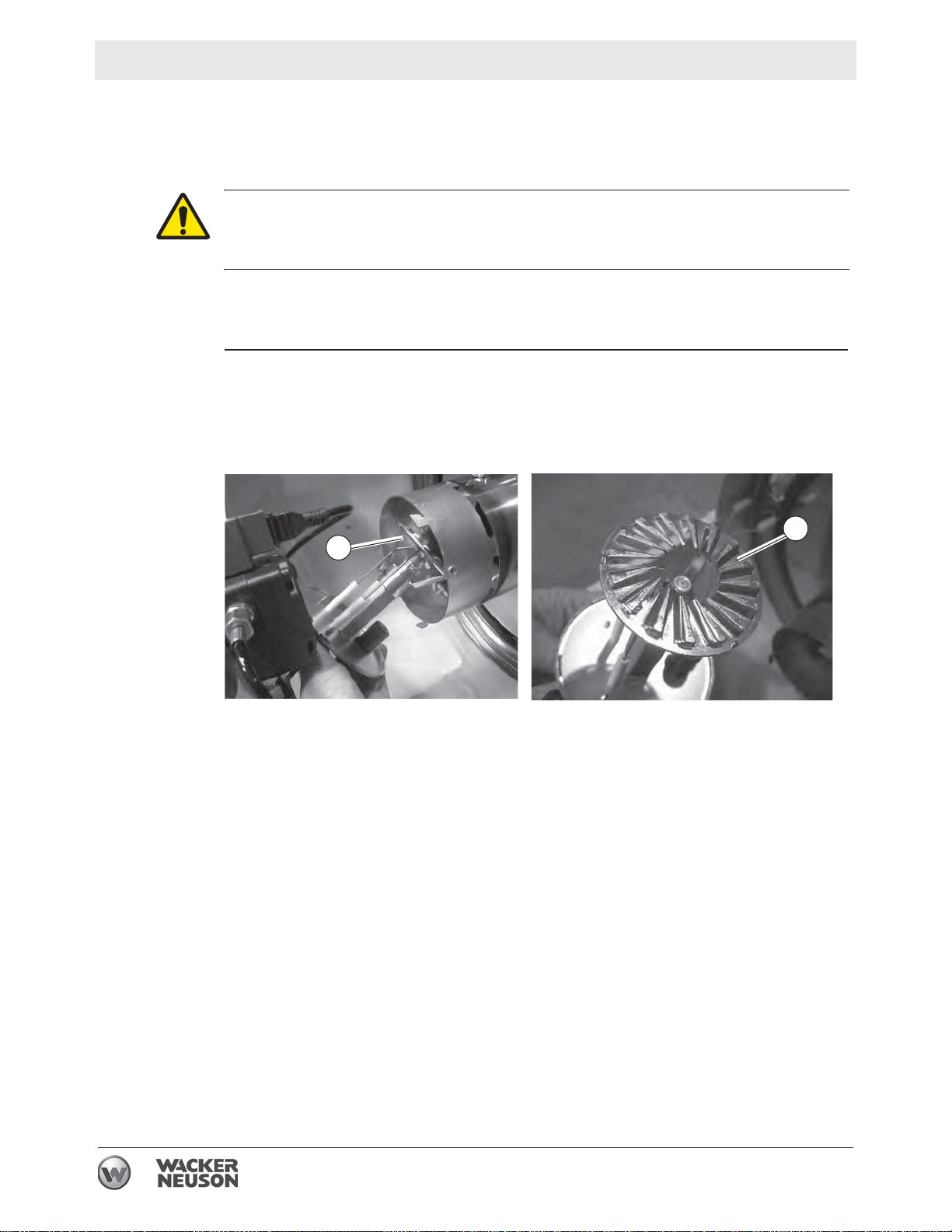
Perform the procedure below to inspect or adjust the electrodes.
1. Remove the burner assembly. See topic Removing and Installing the Burner.
2. Inspect the condition of the electrode tips (a). Replace any damaged or worn
electrodes.
3. Verify the electrode gap is set to the recommended measurement.
wc_tx003210gb.fm
wc_gr010078
Refer to the table below to determine the condition of the electrode tips.
Condition Task
None; ok as is
None; ok as is
Replace
37
Page 38

Burner Setup HDR 155
5.4 Replacing the Burner Nozzle
When
Requirements
Procedure
Replace the burner nozzle annually, or if it is damaged.
Machine shut down and cool to the touch
Machine properly positioned
CAUTION
Hot surface hazard. The machine surfaces may be hot.
f Allow the machine to cool for a minimum of ten minutes before touching it.
To replace the burner nozzle, perform the following procedure.
1. Remove the burner. See topic Removing and Installing the Burner Assembly.
2. Loosen the screw (d) and remove the turbulator (c).
3. Place an adjustable wrench on the nozzle base (a).
4. Place another adjustable wrench on the nozzle (b).
5. Rotate the nozzle counter-clockwise and remove it from the assembly.
Result
6. Install the new nozzle (b) onto the nozzle base (a).
7. Tighten the nozzle (b) using an adjustable wrench. Rotate the wrench
clockwise.
8. Re-install the turbulator (c) and tighten the screw (d).
9. Reinstall the burner assembly. See topic Removing and Installing the Burner
Assembly.
The burner nozzle has been replaced.
wc_tx003210gb.fm
38
Page 39
HDR 155 Burner Setup
5.5 Adjusting the Air Damper
When
Factory
settings
Effects
Procedure
Adjust the air damper when burner performance is in question.
Air damper: 2
Note: This parameter is factory-set.
The air setting has the following effects on combustion.
Higher O
percentage (excess air settings) lowers soot production but raises
2
stack temperature and reduces efficiency: lean mixture.
Lower O
percentage (inadequate air settings) increases efficiency and lowers
2
stack temperature but may cause soot build-up: rich mixture.
Follow the procedure below to adjust the air damper.
1. Initial setting of the air damper should be performed with the machine shut
down.
2. Remove the burner. See topic Removing and Installing the Burner Assembly.
3. Loosen the screws (a).
Result
wc_tx003210gb.fm
4. Using the position pointer (b) to determine position, rotate the air damper
to a higher number to decrease air volume.
to a lower number to increase air volume.
5. Tighten the screws (a).
6. After the air damper has been adjusted, reinstall the burner. See topic
Removing and Installing the Burner Assembly.
The air damper has now been adjusted.
39
Page 40

Burner Setup HDR 155
5.6 Checking and Adjusting the Fuel Pressure
When
Requirements
Background
Procedure
Check the fuel pressure if the machine emits smoke during operation.
Machine shut down and cool to the touch
Power disconnected
Fuel pressure gauge
The information below will show you how to check the fuel pressure on your
machine. Incorrect fuel pressure will result in too much fuel, or too little fuel, to be
supplied to the burner. This will cause the machine to smoke during operation.
To check and/or adjust the fuel pressure, carry out the following procedure.
1. Remove the access panel. See topic Removing the Access Panel .
2. Disconnnect the wire from the solenoid valve (a).
3. Remove the threaded plug (b) from the pressure test port using a hex key
wrench. Set the plug aside to be re-installed later.
d
d
c
b
a
wc_gr010075
4. Install a pressure gauge with adapter (c) in the pressure test port.
5. Start the machine. See topic Starting the Machine.
6. Observe the fuel pressure setting during the first 15 seconds of operation. Refer
to topic Technical Data for the recommended settings.
If Then
The fuel pressure needs adjustment,
The fuel pressure is within specifications skip to step 10.
Note: The machine will shut down at this point and enter safety lock-out mode.
This procedure continues on the next page.
continue to step 7.
40
wc_tx003210gb.fm
Page 41
HDR 155 Burner Setup
Continued from the previous page.
7. Adjust the fuel pressure using the adjusting screw (d).
Clockwise increases fuel pressure
Counter-clockwise decreases fuel pressure
d
_
d
+
c
P
wc_gr010095
NOTICE: Do not adjust the fuel pressure to a setting outside the operational
parameters.
8. Press the reset button.
9. Repeat steps 5–6 to re-check the settings.
10.Remove the pressure gauge (c) from the pressure test port and re-install the
threaded plug (b).
11.Re-connect the solenoid wire.
12.Re-install the access cover.
Result
The fuel pressure has been adjusted.
wc_tx003210gb.fm
41
Page 42
Maintenance HDR 155
6 Maintenance
6.1 Periodic Maintenance Schedule
Interval*
(Hours of service)
Daily 2 Weeks 6 Months Yearly
Task
Inspect and clean the
machine.
Inspect the fuel hoses.
Check fuel level and
pressure.
Clean the fuel filter.
Inspect electrical
components.
Replace the burner nozzle.
Replace the fuel heater
filter.
Clean and check/adjust
burner electrode settings;
replace if necessary.
Use whichever comes first, calendar time or service hours.
*
--- (50) (1000) (1200)
33
3
3
3
3
3
3
As needed or upon changing job sites;
see chapter Burner Setup.
42
wc_tx003207gb.fm
Page 43
HDR 155 Maintenance
6.2 Inspecting and Cleaning the Machine
When
Requirements
Every 50 hours or as needed.
Machine shut down
Machine cool
Machine properly positioned
DANGER
Fire and explosion hazard. Residue from flammable materials such as solvents or
gasoline could ignite and cause a fire or an explosion.
f Do not use flammable materials or solvents to clean the machine.
WARNING
Electric shock hazard. A machine with power connected can cause electric shock.
f Unplug the machine before servicing.
CAUTION
Hot surface hazard. The external surface of the machine or fuel filter canister may
be hot.
f Allow the machine to cool before servicing.
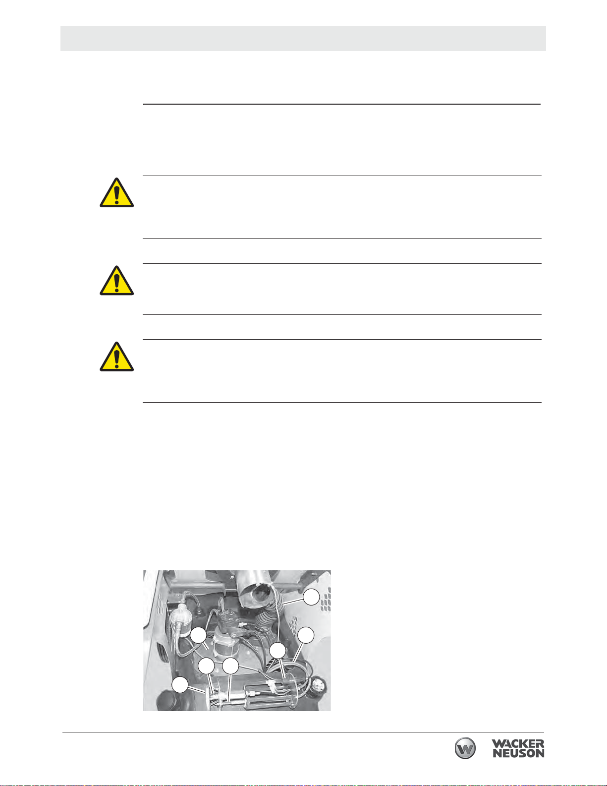
The following internal components of the machine require regular cleaning to
maintain optimum performance.
Enclosure (all areas must be free of dirt and debris)
Ventilator (b)
High-tension connectors (c)
CAD (Cadmium) cell (d)
Flame head (e)
Electrodes (f)
Burner nozzle (g)
Air tube (h)
h
b
c
d
g f
e
wc_tx003207gb.fm
wc_gr010098
43
Page 44

Maintenance HDR 155
Procedure
Result
Perform the procedure below to clean the interior components of the machine.
1. Remove the access cover. See topic Removing the Access Panel.
2. Use compressed air to clean the enclosure and ventilator (b).
3. Inspect and clean the high-tension connnectors and wires (d). Replace any
damaged or worn components.
4. Remove the burner assembly. See topic Removing and Installing the Burner
Assembly.
5. Check/clean the CAD cell. See topic Inspecting and Cleaning the CAD Cell.
6. Check electrodes. See topic Checking and Adjusting the Electrodes.
7. Check the burner nozzle. See topic Replacing the Burner Nozzle.
The machine has been cleaned.
44
wc_tx003207gb.fm
Page 45

HDR 155 Maintenance
6.3 Removing the Access Panel
Requirements
Overview
Procedure
Machine shut down and cool
Machine properly positioned
CAUTION
Hot surface hazard. The machine surfaces may be hot.
f Allow the machine to cool for a minimum of ten minutes before touching it.
Your machine is equipped with removable access panels. The access panels must
be removed in order to maintain and repair certain machine components such as
the burner, electric motor, and fuel pump.
Follow the procedure below to remove the access panel.
1. Shut down the machine and allow it to cool.
2. Disconnect the power cord from the power source.
3. Remove the four bolts that fasten the lift bar (a), remove the lift bar, and set it
aside.
4. Remove the four screws (b) that fasten the access panel (c), remove the panel
and set it aside.
c
b
a
wc_gr010071
5. Perform the required maintenance.
6. When maintenance is complete, re-install the access panel and fasten it with the
screws.
wc_tx003207gb.fm
45
Page 46

Maintenance HDR 155
6.4 Replacing the Fuel Heater Filter
Requirement
Procedure
Machine shut down and cool
CAUTION Hot surface hazard.
The external surface of the fuel filter canister may be hot.
f Allow the machine to cool before servicing.
WARNING Hot fluids.
The fuel inside the fuel filter canister may be hot.
f Wear safety glasses.
Follow the procedure below to change the fuel heater filter.
1. Shut down the machine and allow it to cool.
2. Remove the screw that secures the cover to the housing (a).
Result
wc_gr010015
3. Remove the filter (b).
4. Inspect the O-ring (c). Replace it if it is cracked, damaged, or deformed.
5. Install the new filter.
6. Re-install the cover.
The procedure to replace the fuel heater filter is now complete.
wc_tx003207gb.fm
46
Page 47

HDR 155 Maintenance
0
6.5 Inspecting and Cleaning the Cadmium (CAD) Cell
Requirements
When
Machine shut down and cool to the touch
Machine properly positioned
CAUTION
Hot surface hazard. The machine surfaces may be hot.
f Allow the machine to cool for a minimum of ten minutes before touching it.
Inspect and clean the CAD cell as needed, or while performing other scheduled
maintenance procedures.
To inspect and clean the CAD cell, carry out the following procedure.
1. Remove the access panel. See topic Removing the Access Panel.
2. Twist and pull out the plastic protective holder (1) off the base of the burner
assembly. The CAD cell (2) is inside this plastic holder.
1
2
Result
1
ghi_gr00737
3. Inspect the CAD cell for cleanliness. Be sure the cell is free of debris or soot.
4. Clean the CAD cell if necessary.
NOTICE: Do not use solvents or liquids to clean the CAD cell; use a soft dry cloth.
5. Reinstall the plastic protective holder onto the base of the burner assembly.
The CAD cell is now clean.
wc_tx003207gb.fm
47
Page 48
Maintenance HDR 155
2
6.6 Inspecting the Flame Head
Requirements
When
Procedure
Machine shut down and cool to the touch
Machine properly positioned
CAUTION
Hot surface hazard. The machine surfaces may be hot.
f Allow the machine to cool for a minimum of ten minutes before touching it.
Inspect the flame head prior to the first seasonal use, during regular maintenance,
and as needed.
To inspect the flame head (a), carry out the following procedure.
1. Remove the access panel. See topic Removing the Access Panel .
2. Remove the burner assembly. See topic Removing and Installing the Burner
Assembly. The flame head is attached.
a
a
3. Inspect the flame head for the following:
Wear. Replace if necessary.
Cleanliness. Clean the flame head if necessary.
Thermal stress. Replace if necessary.
4. Re-install the burner assembly. See topic Removing and Installing the Burner
Assembly.
6.7 Inspecting the Electrical Connections
After disconnecting the power cord, check all electrical connections for the
following:
Proper connections. Be sure that all connections are complete and tight.
Corrosion. Clean or replace if necessary.
Damaged wires/connectors. Replace if necessary.
Proper ground.
ghi_gr00738
48
wc_tx003207gb.fm
Page 49

HDR 155 Maintenance
6.8 Long Term Storage
Introduction
When
Preparing for
storage
Stabilizing the
fuel
Extended storage of equipment requires preventative maintenance. Performing
these steps helps to preserve machine components and ensures the machine will
be ready for future use. While not all of these steps necessarily apply to this
machine, the basic procedures remain the same.
Prepare your machine for extended storage if it will not be operated for 30 days or
more.
Follow the procedures below to prepare your machine for storage.
Complete any needed repairs.
After completing the procedures listed above, fill the fuel tank completely and add a
high-quality stabilizer to the fuel.
Choose a stabilizer that includes cleaning agents and additives designed to
coat/protect the cylinder walls.
Make sure the stabilizer you use is compatible with the fuel in your area, fuel
type, grade and temperature range. Do not add extra alcohol to fuels which
already contain it (for example, E10).
Use a stabilizer with a biocide to restrict or prevent bacteria and fungus growth.
Add the correct amount of stabilizer per the manufacturer’s recommendations.
Storing the
machine
Perform these remaining steps to store your machine.
Wash the machine and allow it to dry.
Move the machine to a clean, dry, secure storage location. Block or chock
wheels to prevent machine movement.
Use touch-up paint as needed to protect exposed metal against rust.
Cover the machine. Tires and other exposed rubber items should be protected
from the weather. Either cover them or use a readily available protectant.
wc_tx003207gb.fm
49
Page 50

Basic Troubleshooting HDR 155
7 Basic Troubleshooting
Note: The following symptoms and remedies are some of the more common
issues that have arisen during the history of these machines. These do not
represent all the possibilities. If you need advanced troubleshooting assistance,
please contact Wacker Neuson Product Support.
Problem Cause Remedy
Motor does not start, no
ignition
Motor starts, no ignition, or
cuts out
Electrical current is not
present
Control setting is below
ambient temperature (main,
thermostat, or other control)
Thermostat or other control
is malfuntioning
Electric motor is malfuntioning
Electric motor bearings are
malfuntioning
Condenser is malfunctioning
Electric igniter is malfuntioning
Check the electrical supply
connection.
Check proper positioning
and functioning of switch.
Check fuse.
Check setting of heater
control. If thermostat, make
sure selected temperature
is higher than room temperature.
Replace control device.
Replace electric motor.
Replace electric motor.
Replace condenser.
Check connection of hightension leads to electrodes
and transformer.
Check electrodes setting.
Check electrodes for cleanliness.
Replace high-voltage transformer.
Burner controller is malfuntioning
CAD cell is malfuntioning Replace photocell.
Fuel supply is insufficient Check condition of motor-
Replace control box.
pump plastic coupling.
Check fuel line system
including fuel filter for possible leaks.
Clean or replace oil nozzle.
wc_tx003208gb.fm
50
Page 51

HDR 155 Basic Troubleshooting
Problem Cause Remedy
Motor starts, heater emits
smoke
Heater does not stop Solenoid malfuntioning Replace solenoid coil or
Air supply is insufficient Make sure air inlet and out-
let are unobstructed.
Check setting of combustion air flap.
Clean burner disc.
Air supply is overly sufficient
Fuel is contaminated Replace fuel.
Air leaks present in fuel circuit
Fuel supply is insufficient at
burner
Fuel supply is overly sufficient at burner
Check setting of combustion air flap.
Clean or replace oil filter.
Check fuel line and filter for
possible leaks.
Check pump pressure.
Clean or replace fuel nozzle.
Check pump pressure.
Replace nozzle.
entire solenoid.
wc_tx003208gb.fm
51
Page 52

Technical Data HDR 155
F
8 Technical Data
8.1 Machine
Model HDR 155 - 5200007530
Units
Max. heat output BTU/h 154,000
Fuel pressure psi 174
Fuel consumption gal/h (L/h) 1.1 (4.16)
Power supply
Power consumption W 440
Fuel tank capacity gal/L 17.17 (65)
Noise level at 1m dBA 72
Weight lb(kg) 180 (81.6)
8.2 Dimensions
/V/Hz
1/120/60
52
wc_td000542gb.fm
Page 53

HDR 155 Schematics
9 Schematics
9.1 HDR 155
13
YL
5
GY
BU
wc_gr012088
Ref Description Ref Description
1 Fuse 8 Control
2 Overheat thermostat 9 Remote thermostat plug
3 Solenoid valve 10 Control box
4 CAD cell 11 Heated fuel filter
5 Capacitor
6 Fan motor
7 Electric pilot lamp
12 Tip switch
13 Reset switch
——
Wire Colors
BK Black RD Red YL Yellow OR Orange
GN Green TN Tan BR Brown PU Purple
BU Blue VIO Violet CL Clear SH Shield
wc_tx003209gb.fm
PK Pink WH White GY Gray LB Light blue
53
Page 54

Page 55

Page 56

Important: For spare parts information, please see your Wacker Neuson Dealer, or visit the
㔜せ
䠃㾷
Wacker Neuson website at http://www.wackerneuson.com/.
Wichtig! Informationen über Ersatzteile erhalten Sie von Ihrem Wacker Neuson Händler oder
besuchen Sie die Wacker Neuson Website unter http://www.wackerneuson.com/.
Important : Pour des informations sur les pièces détachées, merci de consulter votre
distributeur Wacker Neuson, ou de visiter le site Internet de Wacker Neuson sur
http://www.wackerneuson.com/.
Importante : Para saber más sobre las piezas de repuesto, póngase en contacto con su
distribuidor de Wacker Neuson o acceda al sitio web de Wacker Neuson en
http://www.wackerneuson.com/.
Importante : Per informazioni sui pezzi di ricambio, contattare il rivenditore Wacker Neuson o
visitare il sito di Wacker Neuson all’indirizzo www.wackerneuson.com.
Viktigt : För information om reservdelar, kontakta din Wacker Neuson-leverantör eller besök
Wacker Neusons webbplats på http://www.wackerneuson.com/.
Tärkeää : Pyydä varaosatietoja Wacker Neusoni n j ällee nmyyj äl tä tai vieraile Wacker Neusonin
web-sivustolla osoitteessa http://www.wackerneuson.com/
Viktig : For informasjon om reservedeler, vennligst kontakt din Wacker Neuson-forhandl er , ell er
besøk Wacker Neusons nettside på http://www.wackerneuson.com/.
Vigtigt : Hvis du ønsker oplysninger om reservedele, bedes du kontakte din Wacker Neuson
forhandler eller besøg Wacker Neuson websiden på http://www.wackerneuson.com/.
Belangrijk! Neem contact op met uw Wacker Neuson dealer of bezoek de website van Wacker
Neuson op http://www.wackerneuson.com/ voor meer informatie over reserveonderdelen.
Importante : Para obter informações sobre as peças sobresselentes, consulte o seu
fornecedor da Wacker Neuson ou aceda ao site Web da Wacker Neuson em
http://www.wackerneuson.com
WaĪne : W celu uzyskania informacji na temat czĊĞci zamiennych skontaktuj siĊ z
przedstawicielem firmy Wacker Neuson lub skorzystaj z witryny internetowej
http://wackerneuson.com/.
DĤležité upozornČní! Pro informace o náhradních dílech, prosím, kontaktujte svého Wacker
Neuson dealera, nebo navštivte webové stránky http://www.wackerneuson.com/.
FONTOS: A pótalkatrészekre vonatkozó informá ciókért kérjük, forduljon Wacker Neuson
kereskedĘjéhez vagy látogasson el a Wacker Neuson weboldalára a következĘ címen:
http://www.wackerneuson.com/.
ȼɚɠɧɨ! Ⱦɥɹ ɨɡɧɚɤɨɦɥɟɧɢɹ ɫ ɢɧɮɨɪɦɚɰɢɟɣ ɨ ɡɚɩɚɫɧɵɯ ɱɚɫɬɹɯ, ɩɨɠɚɥɭɣɫɬɚ, ɨɛɪɚɬɢɬɟɫɶ ɤ
ɦɟɫɬɧɨɦɭ ɬɨɪɝɨɜɨɦɭ ɩɪɟɞɫɬɚɜɢɬɟɥɸ ɤɨɦɩɚɧɢɢ Wacker Neuson ɢɥɢ ɩɨɫɟɬɢɬɟ ɜɟɛ-ɫɚɣɬ
http://www.wackerneuson.com/.
ȈȘȝĮȞIJȚțȩ
: īȚ
Į ʌȜȘȡȠijȠȡȓİȢ ıȤİIJȚțȐ ȝİ IJĮ ĮȞIJĮȜȜĮțIJȚțȐ, ȝȚȜȒıIJİ ȝİ IJȠȞ ĮȞIJȚʌȡȩıȦʌȩ ıĮȢ IJȘȢ
Wacker Neuson, Ȓ İʌȚıțİijșİȓIJİ IJȠȞ ȚıIJȩIJȠʌȠ http://www.wackerneuson.com/.
Važno : Za rezervne dijelove obratite se svom Wacker Neuson prodavaþu ili posjetite mrežne
stranice tvrtke Wacker Neuson: http://www.wackerneuson.com/.
Önemli : Y edek parça bilgileri için Wacker Neuson Bayinize bakÕn veya Wacker Neuson web
sitesini ziyaret edin. http://www.wackerneuson.com/
㒊ရࡢሗࡘ࠸࡚ࡣࠊ࣡ࢵ࣮࢝ࣀࢯࣥࢹ࣮࣮ࣛ࠾ၥ࠸ྜࢃࡏ㡬ࡃࠊ࣡ࢵ
࣮࢝ࣀࢯ࢙ࣥ࢘ࣈࢧࢺ KWWSZZZZDFNHUQHXVRQFRP ࢆࡈぴࡃࡔࡉ࠸ࠋ
ᴿީ༽Ԭؗᚥθ䈭䈘ᛞⲺ့ށ䈰ἤ㔅䬶ᡌ䇵䰤့ށ䈰ἤ㖇ㄏφ
KWWSZZZZDFNHUQHXVRQFRPȾ
Important : Pentru informaĠii referitoare la piesele de schimb, vă rugăm să vă adresaĠi
distribuitorului Wac k er Neuson sau să vizitaĠi site-ul web Wacker Neuson la adresa
http://www.wackerneuson.com/.
ȼɚɠɧɨ : Ɂɚ ɢɧɮɨɪɦɚɰɢɹ ɨɬɧɨɫɧɨ ɪɟɡɟɪɜɧɢ ɱɚɫɬɢ, ɦɨɥɹ, ɨɛɴɪɧɟɬɟ ɫɟ ɤɴɦ ɦɟɫɬɧɢɹ ɞɢɥɴɪ
ɧɚ W
acker Neuson ɢɥɢ ɩɨɫɟɬɟɬɟ ɭɟɛɫɚɣɬɚ ɧɚ Wacker Neuson ɧɚ ɚɞɪɟɫ
http://www.wackerneuson.com/.
Wacker Neuson Produktion GmbH & Co. KG, Preußenstraße 41, D-80809 München,
Wacker Neuson Production Americas LLC, N92W15000 Anthony Ave., Menomonee Falls, WI. 53051
Wacker Neuson Limited - Room 1701–03 & 1717–20, 17/F. Tower 1, Grand Century Place, 193 Prince Edward
Road West, Mongkok, Kowloon, Hongkong. Tel: (852) 3605 5360, Fax: (852) 2758 0032
Tel.: +49-(0)89-3 54 02-0 Fax: +49 - (0)89-3 54 02-390
Tel.: (262) 255-0500 Fax: (262) 255-0550 Tel.: (800) 770-0957
 Loading...